EP0633341A1 - Verfahren und Vorrichtung zum Messen der Position eines Farbstoffabweisblattes - Google Patents
Verfahren und Vorrichtung zum Messen der Position eines Farbstoffabweisblattes Download PDFInfo
- Publication number
- EP0633341A1 EP0633341A1 EP94303515A EP94303515A EP0633341A1 EP 0633341 A1 EP0633341 A1 EP 0633341A1 EP 94303515 A EP94303515 A EP 94303515A EP 94303515 A EP94303515 A EP 94303515A EP 0633341 A1 EP0633341 A1 EP 0633341A1
- Authority
- EP
- European Patent Office
- Prior art keywords
- liquid
- streams
- primary
- deflector blade
- substrate
- Prior art date
- Legal status (The legal status is an assumption and is not a legal conclusion. Google has not performed a legal analysis and makes no representation as to the accuracy of the status listed.)
- Ceased
Links
- 238000000034 method Methods 0.000 title claims abstract description 17
- 239000007788 liquid Substances 0.000 claims abstract description 117
- 230000008569 process Effects 0.000 claims abstract description 13
- 239000000758 substrate Substances 0.000 claims description 40
- 239000003990 capacitor Substances 0.000 claims description 3
- 230000000903 blocking effect Effects 0.000 claims 5
- 230000001105 regulatory effect Effects 0.000 claims 3
- 238000007599 discharging Methods 0.000 claims 1
- 239000000463 material Substances 0.000 abstract description 12
- 238000004043 dyeing Methods 0.000 abstract description 11
- 239000004753 textile Substances 0.000 abstract description 5
- 239000000975 dye Substances 0.000 description 116
- 230000007246 mechanism Effects 0.000 description 8
- 230000013011 mating Effects 0.000 description 7
- 230000000712 assembly Effects 0.000 description 6
- 238000000429 assembly Methods 0.000 description 6
- 239000004973 liquid crystal related substance Substances 0.000 description 5
- 230000008901 benefit Effects 0.000 description 4
- 239000000853 adhesive Substances 0.000 description 3
- 230000001070 adhesive effect Effects 0.000 description 3
- 239000002184 metal Substances 0.000 description 3
- 229910052751 metal Inorganic materials 0.000 description 3
- 239000004033 plastic Substances 0.000 description 3
- 229920003023 plastic Polymers 0.000 description 3
- 238000007789 sealing Methods 0.000 description 3
- 230000004913 activation Effects 0.000 description 2
- 238000003491 array Methods 0.000 description 2
- 239000000919 ceramic Substances 0.000 description 2
- 239000002131 composite material Substances 0.000 description 2
- 238000010586 diagram Methods 0.000 description 2
- 239000004744 fabric Substances 0.000 description 2
- 238000005259 measurement Methods 0.000 description 2
- 230000004044 response Effects 0.000 description 2
- 230000006641 stabilisation Effects 0.000 description 2
- 238000011105 stabilization Methods 0.000 description 2
- 229910001220 stainless steel Inorganic materials 0.000 description 2
- 239000010935 stainless steel Substances 0.000 description 2
- 239000012207 thread-locking agent Substances 0.000 description 2
- 238000004140 cleaning Methods 0.000 description 1
- 230000000295 complement effect Effects 0.000 description 1
- 230000006835 compression Effects 0.000 description 1
- 238000007906 compression Methods 0.000 description 1
- 238000010276 construction Methods 0.000 description 1
- 238000001035 drying Methods 0.000 description 1
- 239000012530 fluid Substances 0.000 description 1
- 238000011065 in-situ storage Methods 0.000 description 1
- 150000002739 metals Chemical class 0.000 description 1
- 238000002156 mixing Methods 0.000 description 1
- 238000012986 modification Methods 0.000 description 1
- 230000004048 modification Effects 0.000 description 1
- 230000003287 optical effect Effects 0.000 description 1
- 239000005060 rubber Substances 0.000 description 1
- 239000000126 substance Substances 0.000 description 1
- 230000001052 transient effect Effects 0.000 description 1
Images




Classifications
-
- D—TEXTILES; PAPER
- D06—TREATMENT OF TEXTILES OR THE LIKE; LAUNDERING; FLEXIBLE MATERIALS NOT OTHERWISE PROVIDED FOR
- D06B—TREATING TEXTILE MATERIALS USING LIQUIDS, GASES OR VAPOURS
- D06B11/00—Treatment of selected parts of textile materials, e.g. partial dyeing
- D06B11/0056—Treatment of selected parts of textile materials, e.g. partial dyeing of fabrics
- D06B11/0059—Treatment of selected parts of textile materials, e.g. partial dyeing of fabrics by spraying
Definitions
- U.S. Patent Nos. 3,443,878 and 3,570,275 describe apparatus and process for the patterned dyeing of a moving textile web wherein continuously flowing streams of liquid normally directed in paths to impinge upon the web are selectively deflected from contact with the web in accordance with pattern information. The webs are thus dyed in a desired pattern and the deflected dye is collected and recirculated for use.
- Each continuously flowing liquid stream is selectively deflected by a stream of air which is discharged, in accordance with pattern information, from an air outlet located adjacent each liquid discharge outlet. The air outlet is positioned to direct the air stream into intersecting relation with the liquid stream and to deflect the liquid into a collection chamber or trough for recirculation.
- the lower portion of the collection chamber contains a deflector blade supportably positioned in spaced relation above the lower wall of the collection chamber.
- This deflector blade is adjustably attached to the lower wall so that its edge can be accurately positioned relative the dye discharge axes of a gun bar to insure prompt and precise interception of the streams when deflected.
- a gunbar is defined as a plurality of dye jets, arranged in spaced alignment, which extend generally above and across the width of a substrate to be treated. Details of such a dyeing apparatus and collection chamber are described and claimed in commonly assigned Mccollough, Jr. et al., U.S. Patent No. 4,019,352 issued April 26, 1977 and hereby incorporated by reference.
- the present invention solves these problems and others in a manner not disclosed in the known prior art.
- the present invention is directed to an apparatus and process for precisely measuring the position of a deflector blade.
- pattern dyeing a moving textile web wherein continuously flowing streams of liquid normally directed in paths to impinge upon the web are selectively deflected from contact with the web in accordance with pattern information, from an air outlet located adjacent each liquid discharge outlet, the air outlet is positioned to direct the air stream into intersecting relation with the liquid stream and to deflect the liquid into a collection chamber or trough for recirculation.
- the lower portion of the collection chamber contains a deflector blade supportably positioned in spaced relation above the lower wall of the collection chamber and wherein means are provided for accurately measuring the position of the deflector blade to facilitate accurate placement of the dye streams on the moving material during the printing process and precise interception of the streams when deflected.
- FIG. 1 depicts, in a side elevational view, a set of eight individual arrays or liquid jet gun bars 26 positioned within frame 22.
- These liquid jet gun bars 26 form part of a pattern dyeing machine to which the present invention is particularly suited.
- Each liquid jet gun bar 26 is comprised of a plurality of dye jets, arranged in spaced alignment, which extend generally above and across the width of substrate 12 and are suitably supported at their ends by attachment to diagonal frame members (one of which, 24, is shown) on either side of the conveyor 14.
- Substrate 12 is supplied from roll 10 and is transported in turn under each liquid jet gun bar 26 by conveyor 14 driven by a suitable motor indicated generally at 16. After being transported under liquid jet gun bars 26, substrate 12 may be passed through other dyeing-related process steps such as drying, fixing, etc.
- FIG. 2 depicts, in schematic form, a side elevation of one dye-emitting liquid jet gun bar of the machine of FIG. 1.
- a separate dye reservoir tank 30 supplies liquid dye under pressure, by means of pump 32 and dye supply conduit means 34, to a primary manifold pipe assembly 36 of the liquid jet gun bar 26.
- This primary manifold pipe assembly 36 does not have to be cylindrical.
- Primary manifold pipe assembly 36 communicates with and supplies dye to dye sub-manifold assembly 40 at suitable locations along their respective lengths.
- Both primary manifold pipe assembly 36 and sub-manifold assembly 40 extend across the width of conveyor 14 on which the substrate to be dyed is transported.
- Sub-manifold assembly 40 is provided with a plurality of spaced, generally downwardly directed dye passage outlets 52 positioned across the width of conveyor 14 that produces a plurality of parallel dye streams that are directed onto the surface of the substrate 12 to be patterned.
- each tube 62 communicates by way of an air supply conduit 64 with an individual air valve, illustrated collectively at "V", which valve selectively interrupts the flow of air to air deflection tube 62 in accordance with pattern information supplied by pattern control system 20.
- V an individual air valve
- Each valve is, in turn, connected by an air supply conduit 28 to pressured air supplied by air compressor 76.
- Each of the valves V which may be of the electromagnetic solenoid type, are individually controlled by electrical signals from a pattern control system 20.
- air deflection tubes 62 direct streams of air that are aligned with and impinge against the continuously flowing streams of dye flowing from dye passage outlets 52 and deflect such dye streams into a collection chamber or trough 80, from which liquid dye may be removed by means of conduit 82 to dye reservoir tank 30 for recirculation.
- the pattern control system 20 for operating solenoid valves V may be comprised of various pattern control means.
- the multiprocessor system 120 provides desired pattern element information to the pattern control system 20 to operate the solenoid valves V.
- the pattern information is transmitted at appropriate times in response to movement by conveyor 14 that is detected by suitable rotary motion sensor or transducer means 18 operatively associated with the conveyor 14 and connected to the pattern control system 20. Details of one means to perform this function may be found in commonly assigned U.S. Patent No. 4,033,154, issued July 5, 1977, which disclosure is hereby incorporated by reference.
- pattern control system 20 As dictated by pattern information, pattern control system 20 generates control signals to selectively "close" appropriate air valves so that, in accordance with the desired pattern, deflecting air streams at specified individual dye passage outlets 52 along the liquid jet gun bars 26 are interrupted and the corresponding dye streams are not deflected, but instead are allowed to continue along their normal discharge paths to strike the substrate 12.
- a colored pattern of dye is placed on the substrate 12 during its passage under the respective liquid jet gun bar 26.
- primary manifold pipe assembly 36 is comprised of a pipe having a flat mating surface that accommodates a corresponding mating surface on dye sub-manifold assembly 40.
- Sub-manifold assembly 40 is comprised of sub-manifold module section 42, grooved dye outlet module 50, and an elongate sub-manifold 46 cooperatively formed by elongate mating channels in sub-manifold module section 42 and grooved dye outlet module 50.
- Sub-manifold module section 42 is attached to primary manifold pipe assembly 36 by bolts (not shown) or other suitable means so that drilled outlet conduits 37 in the mating surface of primary manifold pipe assembly 36 and corresponding drilled passages 44 in the mating surface of elongate sub-manifold 46 are aligned, thereby permitting pressurized liquid dye to flow from the interior of manifold assembly to elongate sub-manifold 46.
- grooved dye outlet module 50 Associated with the mating face of grooved dye outlet module 50 are a plurality of dye outlet module grooves or channels 51, that when grooved dye outlet module 50 is mated to sub-manifold section module 42 as by bolts or other appropriate means (not shown), to form dye passage outlets 52 through which uniform quantities of liquid dye from elongate sub-manifold 46 may be directed onto the substrate 12 in the form of aligned, parallel streams.
- deflecting air jet assembly (not shown) by which individual streams of air from air deflection tubes (not shown) may be selectively directed.
- primary dye collection chamber 80 shown in FIG. 2, which may be formed of suitable sheet material such as stainless steel and extends along the length of the liquid jet gun bar 26, however, any of wide variety of metal, plastic, composites, ceramics and so forth may suffice as throughout this Application.
- primary dye deflector blade 84 Associated with collection chamber 80 is the primary dye deflector blade 84 that is comprised of a thin flexible blade-like member that is positioned parallel and closely adjacent to the row of dye passage outlets 52, as shown in FIG. 3.
- Primary dye deflector blade 84 may be adjustably attached at spaced locations along its length by a primary dye deflector blade adjustment assembly apparatus 85, which will be fully described hereinafter, to a collector plate support member 86 that is both wedge-shaped and elongate, which forms an extension of the floor of collection chamber 80 and extends along the length of liquid jet gun bar 26.
- Primary dye deflector blade 84 may be mounted under tension along its length and aligned with the axes of dye outlet module grooves 51 as shown in FIGS. 3, 11 and 12.
- the tubes 55 attach by means of conventional hardware (i.e., tubing fittings) 59 to the sub-manifold module 42.
- the tubes can be constructed of metal, plastic, rubber, and so forth.
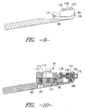
- the primary dye deflector blade adjustment assembly apparatus 85 is found in FIGS. 4, 5, 9, 10, 11 and 12.
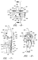
- the ends of the primary dye deflector blade 84 are attached to the collector plate support member 86 by two end mount adjuster assemblies 90 and 91, respectively, as shown in FIGS. 11 and 12.
- Both end mount adjuster assembly 90 and end mount adjuster assembly 91 have substantially similar components and can be described by utilizing the same numerical designation.
- L-shaped member 170 which is a subcomponent of either end mount adjuster assembly 90 or 91.
- top plate member 171 which is moveable in a direction toward and away from the outer edge of the collector plate support member 86 by means of a bolt and washer combination 174 that is inserted through an oval opening 173 and threadedly connected to the L-shaped member 170.
- Movement of the top plate member 171 is accomplished by adjustment of a threaded bolt 175 that enters a through hole 176 in a vertical face segment 177 of the top plate member 171, is threadedly attached to a threaded nut 178, which is pinned to bolt 175 to fix the top plate member 171 in a specific location with reference to the collector plate support member 86.
- Threaded bolt 175 also is inserted in a through hole 179 of the smaller vertical segment of the L-shaped member 170. This configuration is the same for both end mount adjuster assembly 90 and 91, respectively.
- There is a threaded bolt 185 which is threaded through end mount adjuster assembly 91, and in particular, vertical face segment 177 as shown in FIGS.
- end mount adjuster assembly 90 having threaded bolt 190 which is analogous to threaded bolt 185, and is also threaded through vertical face segment 177 as shown in FIG. 11, and is then fixedly attached to a deflector blade holding mechanism 192 that is analogous to deflector blade holding mechanism 187.
- end mount adjuster assembly 90 having threaded bolt 190 which is analogous to threaded bolt 185, and is also threaded through vertical face segment 177 as shown in FIG. 11, and is then fixedly attached to a deflector blade holding mechanism 192 that is analogous to deflector blade holding mechanism 187.
- nut 191 similar to nut 186 to provide adjustment and is located on the outside of the end mount adjuster assembly 91.
- Deflector blade holding mechanism 192 is structured as a mirrored complement to deflector holding mechanism 187 so that subcomponents thereof will be designated identically.
- the primary dye deflector blade 84 has each lateral side wrapped around a piece of wire 129 and held in position between the rectangular notch 131 and the rectangular ridge 132.
- slide member 134 in the form of a dowel rod that is press fitted into end mount adjuster assembly 91 and is inserted in a through hole in bottom plate portion 130 of defector blade holding mechanism 187.
- This provides horizontal stabilization for the primary dye deflector blade 84.
- slide member 135 in the form of a dowel rod that is press fitted into end mount adjuster assembly 90 and is inserted in a through hole in bottom plate portion 130 of defector blade holding mechanism 192 for the same purpose of stabilization.
- the preferred embodiment spaces several primary dye deflector blade adjustment assembly apparatus 85 along the length of the collector plate support member 86 to prevent movement of the primary dye deflector blade 84.
- the primary dye deflector blade adjustment assembly apparatus 85 is adjustable in a direction toward and away from the longitudinal edge of the collector plate support member 86 in a substantially perpendicular relationship.
- the primary dye deflector blade adjustment assembly apparatus 85 includes a rectangular adjuster arm 217 having a retaining clip 219 attached at one end by means of rivets 221, but any means of mechanical interconnection will suffice such as bolts, adhesives and so forth, as is typical throughout this Application.
- the retaining clip 219 holds the primary dye deflector blade 84 in place to prevent vibration.
- the rectangular adjuster arm 217 is held in position by a u-shaped channel member 214 on each side for movement of the entire rectangular adjuster arm 217.
- the u-shaped channel member 214 is attached to the collector plate support member 86. This u-shaped channel member 214 provides movement fore and aft substantially perpendicular to the longitudinal axis of the primary dye deflector blade 84 so that the primary dye deflector blade can move toward and away from the dye passage outlets 52.
- the u-shaped channel 214 is secured to the collector plate support member 86 by means of two flat head screws 228, 229, respectively that are threadedly attached to a round sealing disk 222, as shown in FIG. 4.
- the flat head screws 228, 229 penetrate through holes 234, 235 in the u-shaped channel member 224 that are tapered to prevent passage of the heads of the flat head screws 228, 229 that are designated by numerals 237 and 238, respectively.
- There is an o-ring 232 that seals the space between the round sealing disk 222 and the collector plate support member 86. As shown in FIGS. 4 and 12, there is access to the round sealing disk 222 by means of opening 224.
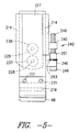
- an adjustment mechanism for providing movement fore and aft substantially perpendicular to the longitudinal axis of the primary dye deflector blade 84 so that the primary dye deflector blade 84 can move toward and away from the dye passage outlets 52 that is generally indicated by numeral 242, as shown in FIG. 5.
- There is a threaded adjustment bracket 245 that is attached to the u-shaped channel member 214.
- There is a through-hole adjustment member 246 that is attached to rectangular adjustment arm 217.
- There is a threaded cap screw 248 that is positioned within through-hole adjustment member 246 with the head 249 of the threaded cap screw 248 positioned adjacent the through-hole adjustment member 246.
- the threaded cap screw 248 is, also, threadedly interconnected into the threaded adjustment bracket 245.
- the rectangular adjustment arm 217 is held in position by means of retaining collar 251 that is threadedly tightened against two Belleville® washers 253 and positioned against the through-hole adjustment bracket 246. After tightening the retaining collar 251 against the Belleville® washers 253, the retaining collar 251 is locked to the threaded cap screw 248 by means of an anaerobic adhesive such as Loctite® thread locking compound.
- an anaerobic adhesive such as Loctite® thread locking compound.
- the primary dye deflector blade adjustment assembly apparatus 85 not protrude below the lower surface of the collector plate support member 86 to take up excess vertical space in case a cleaning shield is utilized like that disclosed in commonly assigned U.S. Patent No. 4,993,242 issued February 19, 1991, which is hereby incorporated by reference.
- a means for determining the position of the primary dye deflector blade 84 is generally denoted by numeral 301. Since the primary dye deflector blade 84 is preferably constructed out of a thin strip of stainless steel (.010" x 1.25"), it is relatively easy to move. This means that any method of measuring the position of the primary dye deflector blade 84 that involves contact is likely to move the defector blade 84 and make the measurement meaningless.
- a miniature photocell/light source unit 305 such as an optical isolator, with an approximately linear response over a few thousandths of an inch of movement of an occluding body is used to sense the location of the edge of the primary dye deflector blade 84.
- This miniature photocell/light source unit 305 is preferably a HONEYWELL® HOA1875-2, however there are numerous approximately linear photocells in combination with a light source that may be used.
- the miniature photocell/light source unit 305 is mounted to the end of a rectangular first arm member 307 by means of a threaded hex-head bolt 386.
- First arm member 307 is fixedly attached by means of a threaded hex-head bolt and washer 385 through a oval slot 387 into a u-shaped channel 375 in positioning block 309 that positions miniature photocell/light source unit 305 back and forth in relation to the primary dye deflector blade 84.
- the positioning block 309 is moved by means of adjustable screw 310 that is loaded by means of a spring 303. There is a set screw 399 that locks the positioning block 309 into one fixed position.
- the positioning block 309 is also located within a u-shaped channel 370 within the first side 360 of a five sided open rectangular box, generally indicated by numeral 355.
- the second side 361 or bottom of the rectangular box 355 is located opposite the first side 360 of the five sided open rectangular box 355 and has a threaded hole for a set screw 399. Adjacent the first side 360 and the second side 361 is the third side 362 and the fourth side 363 in opposed relationship. There is a first pair of recessed hex-head bolts 367, 368 respectively that attach fourth side 363 to second side 361 and an second pair of recessed hex-head bolts (not shown) that attach third side 362 to second side 361.
- the fifth side 364 provides a cover and is mounted adjacent to the first side 360, second side 361, third side 362 and fourth side 363 respectively.
- This means for determining the position of the primary dye deflector blade 301 can be formed out of any of a wide variety of materials including metals, plastics, composites, ceramics, and so forth.
- a sensor position locator 325 that keys against the rear corner of the grooved dye outlet module 50, as shown in FIG. 3.
- the grooved dye outlet module should be accurately machined for precision adjustment of the primary dye deflector blade 84.
- the sensor position locator 325 is attached by a series of four recessed hex-head bolts with two hex-head bolts 391, 392 attached to the third side 362 and the fourth side 363, respectively, and two inner hex-head bolts 393 and 394 that are attached to the fourth side 364 of the five sided open rectangular box 355.
- the miniature photocell/light source unit 305 is held so that the edge of the primary dye deflector blade 84 is inside the miniature photocell/light source unit's 305 field of view.
- the miniature photocell/light source unit 305 is electrically connected to the electrical components mounted on a circuit board 330.
- Circuit board 330 may optionally be attached to the five sided open rectangular box 355.
- the miniature photocell/light source unit 305 is powered by a nine (9) volt battery 332 that is connected and disconnected by means of a momentary on/off push button switch 334.
- the photocell/light source unit 305 is divided into a photocell 336 and the light source in the form of a light emitting diode 337.
- the first parallel path 340 allows 12.2 milliamperes to flow through a 680 ohm, 1/4 watt, five percent (5%) precision resistor 348 and then through the light emitting diode 337 thereby causing activation thereof and then connecting with the negative terminal of the nine (9) volt battery 332.
- the second parallel path 322 for current flow from the positive terminal of the nine (9) volt battery 332 allows current to flow through a 1,000 ohm potentiometer 342 then through the photocell 336 and finally through a 10,000 ohm, one-fourth (1/4) watt, five percent (5%) precision resistor 344 and finally and back to the negative terminal of the nine (9) volt battery 332.
- the light emitting diode 337 must shine light on the photocell 336 in order for current to flow through the second parallel path 322.
- the first parallel path 340 allows 12.2 milliamperes to flow through a 680 ohm, 1/4 watt, five percent (5%) precision resistor 348 and then through the light emitting diode 337 thereby causing activation thereof and then connecting with the negative terminal of the nine (9) volt battery 332.
- the third parallel path 350 allows 4 milliamperes to flow through a 1,000 ohm, 1/4 watt, five percent (5%) precision resistor 351. After current passes through this resistor 351, it encounters three more parallel paths 377, 378, and 380, respectively, each containing one component connected to the negative terminal of the nine (9) volt battery 332.
- the liquid crystal display volt meter 353 measures voltage across the 10,000 ohm resistor 344 by means of a positive input path 307 connected between photocell 336 and the 10,000 ohm resistor 344.
- a non-limiting example of a digital voltmeter 353 is an ACCULEX® DP-650 with four digits and a minus sign on the liquid crystal display.
- the circuit board 330 can be manufactured by any type of photo or chemical etching-type process. For convenience, the circuit board 330 may be enclosed within a box (not shown).
- the optimum position of the primary dye deflector blade 84 is determined by the primary dye deflector blade adjustment assemblies 85 in which the end of the primary dye deflector blade 84 is moved toward the dye passage outlets 52 until the edge of the blade 84 contacts the stream from the dye passage outlets 52, as shown in FIG. 3.
- the first step is to adjust one end mount adjuster assembly 91, as shown in FIG. 10, by turning threaded bolt 95 or 96 to move the primary dye deflector blade 84 away from the stream emitting from the dye passage outlets 52.
- the opto-electric blade position sensor 301 is positioned adjacent to the grooved dye outlet module 50 containing an end dye passage outlet and located by holding its reference surfaces against the mating surfaces of the grooved dye outlet module 50.
- the position of the opto-electric blade position sensor 301 is adjusted so that the five (5) digit volt meter 353 is at mid range with the primary dye deflector 84 obstructing a portion of the light emitted from the light emitting diode 337.
- This adjustment of opto-electric blade position sensor 301 with respect to reference surfaces will be used at all other primary dye deflector blade adjustment assemblies 85 and the opposite end mount adjuster assembly 91 to locate the proper primary dye deflector blade 84 position.
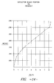
- FIG. 14 there is a substantially linear relationship between the voltage readout between zero to eight volts and the deflector blade position between zero and .035 inches.
- deflector blade adjustment assembly apparatus 85 includes a rectangular adjuster arm 217 having a retaining clip 219 attached at one end by means of rivets 221.
- the retaining clip 219 holds the primary dye deflector blade 84 in place to prevent vibration.
- the rectangular adjustment arm 217 is held in position by means of a u-shaped channel member 214 on each side for movement of the entire rectangular adjuster arm 217.
- the u-shaped channel member 214 is attached to the collector plate support member 86.
- There is a threaded adjustment bracket 245 that is attached to the u-shaped channel member 214.
- There is a through-hole adjustment member 246 that is attached to rectangular adjustment arm 217.
- a threaded cap screw 248 that is positioned within through-hole adjustment member 246 with the head 249 of the threaded cap screw 248 positioned adjacent the through-hole adjustment member 246.
- the threaded cap screw 248 is, also, threadedly interconnected into the threaded adjustment bracket 245.
- the rectangular adjustment arm 217 is held in position by means of retaining collar 251 that is threadedly tightened against two Belleville® washers 253 and positioned against the through-hole adjustment member 246. After tightening the retaining collar 251 against the Belleville® washers 253, the retaining collar 251 is locked to the threaded cap screw 248 by means of an anaerobic adhesive such as Loctite® thread locking compound.
- an anaerobic adhesive such as Loctite® thread locking compound.
- the opto-electric blade position sensor 301 is held against the grooved dye outlet module 50 and then the digital voltage value is read from the five (5) digit digital voltmeter 353 and the primary dye deflector blade 84 is moved by means of moving the retaining collar 251 back and forth along threaded cap screw 248 so that so that the primary dye deflector blade 84 can move toward and away from the dye passage outlets 52 so that the same numerical voltage value as that found at the end mount adjuster assembly 90.
- This same procedure is used for all the remaining intermediate primary dye deflector blade adjustment assemblies 85 and the remaining end mount adjuster assembly 91.
- the primary dye deflector blade 84 position should be re-checked and re-adjusted if necessary. Please note that the air deflector tubes 62 will need to be disconnected and moved out of the way in order to utilize the opto-electric blade position sensor 301.
Landscapes
- Engineering & Computer Science (AREA)
- Chemical & Material Sciences (AREA)
- Materials Engineering (AREA)
- Textile Engineering (AREA)
- Treatment Of Fiber Materials (AREA)
- Length Measuring Devices By Optical Means (AREA)
Applications Claiming Priority (2)
| Application Number | Priority Date | Filing Date | Title |
|---|---|---|---|
| US88502 | 1993-07-07 | ||
| US08/088,502 US5325556A (en) | 1993-07-07 | 1993-07-07 | Method and apparatus for measuring the position of a dye deflector blade |
Publications (1)
| Publication Number | Publication Date |
|---|---|
| EP0633341A1 true EP0633341A1 (de) | 1995-01-11 |
Family
ID=22211745
Family Applications (1)
| Application Number | Title | Priority Date | Filing Date |
|---|---|---|---|
| EP94303515A Ceased EP0633341A1 (de) | 1993-07-07 | 1994-05-17 | Verfahren und Vorrichtung zum Messen der Position eines Farbstoffabweisblattes |
Country Status (4)
| Country | Link |
|---|---|
| US (1) | US5325556A (de) |
| EP (1) | EP0633341A1 (de) |
| JP (1) | JPH07150463A (de) |
| AU (1) | AU669066B2 (de) |
Families Citing this family (4)
| Publication number | Priority date | Publication date | Assignee | Title |
|---|---|---|---|---|
| JP3029817B2 (ja) * | 1997-11-11 | 2000-04-10 | 西撚糸株式会社 | 糸条側面の部分染糸 |
| US6343493B2 (en) * | 2000-03-31 | 2002-02-05 | Milliken & Company | Alignment system for patterning device |
| US20120034388A1 (en) | 2010-08-04 | 2012-02-09 | Love Iii Franklin S | Apparatus and method for controlled application of liquid streams to a substrate |
| US20120031327A1 (en) | 2010-08-04 | 2012-02-09 | Love Iii Franklin S | Apparatus for controlled application of liquid streams to a substrate with diverted liquid collection system |
Citations (4)
| Publication number | Priority date | Publication date | Assignee | Title |
|---|---|---|---|---|
| US3393411A (en) * | 1964-07-06 | 1968-07-23 | Stevens & Co Inc J P | Process for dyeing pile material with various colored dyes from a plurality of streams |
| US3443878A (en) * | 1963-12-04 | 1969-05-13 | Halbmond Teppiche Veb | Method of continuously dyeing textile webs and the like |
| US3570275A (en) * | 1965-02-08 | 1971-03-16 | Halbmond Teppiche Veb | Apparatus for the continuous dyeing of textile webs and the like |
| US4019352A (en) * | 1976-02-23 | 1977-04-26 | Milliken Research Corporation | Apparatus for the application of liquids to moving materials |
Family Cites Families (25)
| Publication number | Priority date | Publication date | Assignee | Title |
|---|---|---|---|---|
| NL124509C (de) * | 1962-05-23 | |||
| GB1268112A (en) * | 1968-06-15 | 1972-03-22 | Schroers Co Textilausruest | Improved method of dyeing textiles and in apparatus therefor |
| NL6906009A (de) * | 1968-11-18 | 1970-10-20 | ||
| DK139982C (da) * | 1970-03-05 | 1979-10-29 | Schroers Co Textilausruest | Apparat til kontinuerlig farvning af tekstilstoffer i forskellige farver eller farvetoner |
| US3688530A (en) * | 1971-06-15 | 1972-09-05 | Stephen C Harris | Polychromatic dye applicator |
| US3942342A (en) * | 1974-05-17 | 1976-03-09 | Deering Milliken Research Corporation | Apparatus for dyeing and printing materials |
| US3937045A (en) * | 1974-01-03 | 1976-02-10 | Deering Milliken Research Corporation | Dyeing and printing of materials |
| US3985006A (en) * | 1974-01-03 | 1976-10-12 | Deering Milliken Research Corporation | Dyeing and printing of materials |
| ZA747960B (en) * | 1974-01-03 | 1975-12-31 | Deering Milliken Res Corp | Jet dyeing apparatus |
| US3892109A (en) * | 1974-05-17 | 1975-07-01 | Deering Milliken Res Corp | Jet dyeing and washing apparatus |
| US3894413A (en) * | 1974-01-03 | 1975-07-15 | Deering Milliken Res Corp | Dyeing and printing of materials |
| US3942343A (en) * | 1974-05-17 | 1976-03-09 | Deering Milliken Research Corporation | Apparatus for dyeing and printing materials having improved dye recirculation means |
| US3969779A (en) * | 1974-07-30 | 1976-07-20 | Deering Milliken Research Corporation | Dyeing and printing of materials |
| US4059880A (en) * | 1974-01-03 | 1977-11-29 | Milliken Research Corporation | Method of making an apparatus for dyeing and printing of materials |
| US3939675A (en) * | 1974-05-17 | 1976-02-24 | Deering Milliken Research Corporation | Apparatus for dyeing and printing materials having improved means for support thereof |
| US4033154A (en) * | 1974-06-07 | 1977-07-05 | Deering Milliken Research Corporation | Electronic control system for dyeing and printing materials |
| US4034584A (en) * | 1974-07-30 | 1977-07-12 | Milliken Research Corporation | Dyeing and printing of materials |
| US4116626A (en) * | 1976-05-17 | 1978-09-26 | Milliken Research Corporation | Printing of pattern designs with computer controlled pattern dyeing device |
| US4055868A (en) * | 1976-11-29 | 1977-11-01 | Milliken Research Corporation | Dyeing method |
| US4058991A (en) * | 1976-11-29 | 1977-11-22 | Milliken Research Corporation | Dyeing machine |
| US4095444A (en) * | 1977-06-15 | 1978-06-20 | Milliken Research Corporation | Apparatus for the application of liquids to moving materials |
| US4382262A (en) * | 1981-03-23 | 1983-05-03 | Joseph Savit | Multicolor jet printing |
| US4392366A (en) * | 1981-04-28 | 1983-07-12 | Milliken Research Corporation | Flow controller |
| US4434632A (en) * | 1981-11-25 | 1984-03-06 | Milliken Research Corporation | Apparatus for the application of liquids to moving materials |
| US4648250A (en) * | 1984-06-15 | 1987-03-10 | Suminoe Textile Co., Ltd. | Apparatus for dyeing a web of fabric continuously |
-
1993
- 1993-07-07 US US08/088,502 patent/US5325556A/en not_active Expired - Fee Related
-
1994
- 1994-05-17 AU AU63161/94A patent/AU669066B2/en not_active Ceased
- 1994-05-17 EP EP94303515A patent/EP0633341A1/de not_active Ceased
- 1994-06-10 JP JP6129336A patent/JPH07150463A/ja not_active Ceased
Patent Citations (4)
| Publication number | Priority date | Publication date | Assignee | Title |
|---|---|---|---|---|
| US3443878A (en) * | 1963-12-04 | 1969-05-13 | Halbmond Teppiche Veb | Method of continuously dyeing textile webs and the like |
| US3393411A (en) * | 1964-07-06 | 1968-07-23 | Stevens & Co Inc J P | Process for dyeing pile material with various colored dyes from a plurality of streams |
| US3570275A (en) * | 1965-02-08 | 1971-03-16 | Halbmond Teppiche Veb | Apparatus for the continuous dyeing of textile webs and the like |
| US4019352A (en) * | 1976-02-23 | 1977-04-26 | Milliken Research Corporation | Apparatus for the application of liquids to moving materials |
Also Published As
| Publication number | Publication date |
|---|---|
| JPH07150463A (ja) | 1995-06-13 |
| US5325556A (en) | 1994-07-05 |
| AU6316194A (en) | 1995-01-19 |
| AU669066B2 (en) | 1996-05-23 |
Similar Documents
| Publication | Publication Date | Title |
|---|---|---|
| NO162684B (no) | Fotometerhode for smaa maalevolum. | |
| CA1211281A (en) | Flow controller | |
| US5325556A (en) | Method and apparatus for measuring the position of a dye deflector blade | |
| US4434632A (en) | Apparatus for the application of liquids to moving materials | |
| US3970394A (en) | Densitometer head with fiber optics | |
| US3942343A (en) | Apparatus for dyeing and printing materials having improved dye recirculation means | |
| US3939675A (en) | Apparatus for dyeing and printing materials having improved means for support thereof | |
| US5613790A (en) | Apparatus for normalizing top-of-form registration in a moving web printer | |
| GB2074098A (en) | Dye jet printing | |
| US4584854A (en) | Air comb arrangement for jet dyeing machine | |
| US5161395A (en) | Apparatus for dyeing and printing materials having improved means for support thereof | |
| US4202189A (en) | Apparatus for the application of liquids to moving materials | |
| US4616794A (en) | Air comb arrangement for jet dyeing machine | |
| US6481836B1 (en) | Modular ink mounting assembly and ink delivery system | |
| KR930005044A (ko) | 펠릿직경검사 시스템 및 그 검사방법 | |
| US4736209A (en) | Tensionable ground electrode for fluid-jet marking apparatus | |
| EP1268908B1 (de) | Bemusterungsvorrichtung | |
| SE441240B (sv) | Apparat for att pafora ferg pa en rorlig bana innefattande elastiska stenger mellan applikator och stodram samt organ som reglerar applikatorns lege | |
| EP0039533B1 (de) | Densitometer | |
| HU211380B (en) | Method and apparatus for transporting media of measured quantity | |
| US4639737A (en) | Tensionable electrodes for charging and/or deflecting fluid droplets in fluid-jet marking apparatus | |
| GB2205381A (en) | Tube securing apparatus | |
| FR2588199A1 (fr) | Appareil d'application d'un liquide sur un materiau mobile, notamment pour la teinture des matieres textiles |
Legal Events
| Date | Code | Title | Description |
|---|---|---|---|
| PUAI | Public reference made under article 153(3) epc to a published international application that has entered the european phase |
Free format text: ORIGINAL CODE: 0009012 |
|
| AK | Designated contracting states |
Kind code of ref document: A1 Designated state(s): BE DE GB NL |
|
| 17P | Request for examination filed |
Effective date: 19950204 |
|
| 17Q | First examination report despatched |
Effective date: 19961014 |
|
| GRAG | Despatch of communication of intention to grant |
Free format text: ORIGINAL CODE: EPIDOS AGRA |
|
| STAA | Information on the status of an ep patent application or granted ep patent |
Free format text: STATUS: THE APPLICATION HAS BEEN REFUSED |
|
| 18R | Application refused |
Effective date: 19980302 |