EP0633084A1 - Drilling device for making holes with undercuttings - Google Patents
Drilling device for making holes with undercuttings Download PDFInfo
- Publication number
- EP0633084A1 EP0633084A1 EP94106713A EP94106713A EP0633084A1 EP 0633084 A1 EP0633084 A1 EP 0633084A1 EP 94106713 A EP94106713 A EP 94106713A EP 94106713 A EP94106713 A EP 94106713A EP 0633084 A1 EP0633084 A1 EP 0633084A1
- Authority
- EP
- European Patent Office
- Prior art keywords
- drilling
- drilling spindle
- bearing
- deflection element
- spindle
- Prior art date
- Legal status (The legal status is an assumption and is not a legal conclusion. Google has not performed a legal analysis and makes no representation as to the accuracy of the status listed.)
- Granted
Links
- 238000005553 drilling Methods 0.000 title claims abstract description 53
- 230000005540 biological transmission Effects 0.000 claims description 2
- 239000000919 ceramic Substances 0.000 claims 1
- 239000004567 concrete Substances 0.000 claims 1
- 239000004575 stone Substances 0.000 claims 1
- 238000000034 method Methods 0.000 description 6
- 229910003460 diamond Inorganic materials 0.000 description 5
- 239000010432 diamond Substances 0.000 description 5
- 238000005520 cutting process Methods 0.000 description 2
- 230000002028 premature Effects 0.000 description 2
- 238000004519 manufacturing process Methods 0.000 description 1
- 238000003892 spreading Methods 0.000 description 1
- 238000003756 stirring Methods 0.000 description 1
- 238000003860 storage Methods 0.000 description 1
Images


Classifications
-
- B—PERFORMING OPERATIONS; TRANSPORTING
- B23—MACHINE TOOLS; METAL-WORKING NOT OTHERWISE PROVIDED FOR
- B23B—TURNING; BORING
- B23B51/00—Tools for drilling machines
- B23B51/0018—Drills for enlarging a hole
- B23B51/0027—Drills for enlarging a hole by tool swivelling
Definitions
- the invention relates to a device for producing boreholes with an undercut according to the preamble of claim 1.
- Such drill holes with an undercut can also be made in facade panels or the like, but the undercuts there must be carried out very precisely so that when the expansion anchor is inserted and spread out, the expansion pressure is not too high. One too high spreading pressure can cause part of the facade panel to burst.
- these devices are designed in such a way that automatic, machine-controlled swiveling is made possible.
- Drilling tools are also used which have a drill head equipped with diamond chips. When the drilling tool clamped in alignment with the drive axis of the drilling machine is immersed in the facade panel, the entire end face of the truncated cone-shaped drilling head comes into engagement. This requires a high contact pressure of the drilling tool, which, due to the lower cutting speed in the center of the end face of the drilling tool, leads to premature dulling of the diamond chips. This significantly reduces the service life of the drilling tool.
- the invention has for its object to provide a device for producing boreholes with an undercut, in which the wobble movement required to rub out an undercut is carried out mechanically.
- the wobble movement during the drilling process has the advantage that the drilling can be carried out more easily and thus more gently. Without such a wobbling movement, low cutting speeds occur in the center of the drill head equipped with diamond chips, which lead to premature dulling of the diamond chips.
- the deflection element preferably rotates at a lower speed than the drilling spindle.
- the drilling spindle and deflecting element can be driven by separate drive motors, but it is more advantageous to provide a common drive which drives the drilling spindle and deflecting element at different speeds via belt or gear drives.
- a common drive can be realized more compactly, with less weight and less costs.
- the lower weight is particularly advantageous for the generation of the wobble movement, since a lower mass contributes to the fact that higher wobble speeds can be achieved.
- the deflecting element preferably protrudes from a rotating ring which surrounds the drilling spindle. To generate the The rotary ring is now set in rotation, the deflecting element projecting from it pivoting the pivotably mounted drilling spindle from the vertical position.
- the deflection element can be a roller standing on the ring or a bearing element, for example a four-point bearing. Such a four-point bearing can be operated much more wear-free than a roller, but a deflection element designed as a roller is less expensive to produce.
- the device shown in FIG. 1 consists of a feed unit 1, a drive unit 2 and a drilling spindle 4 mounted in a swivel device 3.
- the feed device 1 moves the drive device 2 together with the swivel device 3 and the drilling spindle 4 in the vertical direction in order to lower the drilling head 5 in order to create a borehole and then to be able to pull it out again.
- the vertical feed movement is represented by the double arrow 6.
- the drive device 2 consists of a drive motor 7 and a belt transmission 8, which drives the drilling spindle 4 via a belt 9 and a rotary ring 11 via a belt 10.
- the drilling spindle 4 lies in a bearing sleeve 12 which is mounted in a pivot bearing 13.
- the rotating ring 11 is mounted on the bearing sleeve 12 by means of a ball bearing 14.
- the bearing sleeve 12 carries the entire drive device 2 via a holder 15, which is thus pivotably mounted in the pivot bearing 13, just like the drilling spindle 4.
- the swivel range is indicated by broken lines 16.
- the drilling center axis 17 runs through the bearing center 18 of the pivot bearing 13, about which the drilling spindle 4 can be deflected or pivoted.
- the drilling spindle 4 is deflected by a deflection element designed as a roller 19, which projects laterally on the rotating ring 11 and presses against a height-adjustable ring 20 from above.
- a deflection element designed as a roller 19 which projects laterally on the rotating ring 11 and presses against a height-adjustable ring 20 from above.
- the rotary ring 11 is raised on one side, so that the entire arrangement, consisting of the drilling spindle 4 and the drive device 2 in the pivot bearing 13, is tilted slightly.
- a bearing flange 21 fastened to the bearing bush 12 rests on a rubber bearing 22 designed as an O-ring, which thus enables elastic deflection of the bearing bush 12 and the drilling spindle 4 stored therein.
- the ring 20 can be adjusted in height by means of a cylinder 23 in order to obtain a larger or smaller deflection and thus a larger or smaller wobble movement on the drill head 5.
- FIG. 2 shows an embodiment with a bearing element 24 as a deflection element.
- the bearing element 24 is designed as a four-point bearing and is connected to the rotary ring 11 via a lever 25. This is also done here Height adjustment by a cylinder 23 which engages the height-adjustable ring 20.
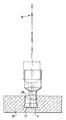
- FIG. 3 illustrates the drilling of a borehole 26 with an undercut 27 in a facade panel 28.
- a drilling head 5 is used for this purpose, which is coated with diamond chips on its end face and on its conical lateral surface.
- the undercut 27 is rubbed out by a wobble movement around the bearing center 18.
- the cylindrical section of the borehole 26 is also created with a wobble movement, which, however, has a smaller amplitude than the wobble movement when the undercut 27 is rubbed out.
- the feed for the drill head 5 is switched off during the wiping out process of the undercut 27.
- the drilling head 5 is part of a drilling tool 55 (FIG. 1) which is known per se and which is connected to the drilling spindle (4).
Landscapes
- Engineering & Computer Science (AREA)
- Mechanical Engineering (AREA)
- Processing Of Stones Or Stones Resemblance Materials (AREA)
- Drilling And Boring (AREA)
- Perforating, Stamping-Out Or Severing By Means Other Than Cutting (AREA)
- Pens And Brushes (AREA)
- Making Paper Articles (AREA)
- Purification Treatments By Anaerobic Or Anaerobic And Aerobic Bacteria Or Animals (AREA)
Abstract
Description
Die Erfindung betrifft eine Vorrichtung zur Herstellung von Bohrlöchern mit Hinterschneidung gemäß der Gattung des Anspruchs 1.The invention relates to a device for producing boreholes with an undercut according to the preamble of claim 1.
Zur Herstellung von Bohrlöchern mit Hinterschneidung sind Vorrichtungen bekannt, die eine mit einer kalottenförmigen Mulde versehene Lagerbuchse aufweisen, in der ein mit einem Bund versehenes Bohrwerkzeug abgestützt und verschwenkbar gelagert ist. Durch Ausschwenken des Bohrwerkzeuges bei gleichzeitiger Rührbewegung wird von den am Bohrwerkzeug angeordneten Seitenschneiden im Bereich des Bohrlochgrundes eine Hinterschneidung ausgerieben, in die ein Spreizdübel mit aufspreizbarer Spreizhülse formschlüssig einsetzbar ist.For the production of boreholes with an undercut, devices are known which have a bearing bush provided with a spherical trough, in which a drilling tool provided with a collar is supported and pivotably mounted. By swiveling out the drilling tool with a simultaneous stirring movement, an undercut is rubbed out from the side cutters arranged on the drilling tool in the region of the bottom of the borehole, into which an expansion dowel with an expandable expansion sleeve can be inserted in a form-fitting manner.
Derartige Bohrlöcher mit Hinterschneidung lassen sich auch in Fassadenplatten oder dergleichen einbringen, jedoch müssen dort die Hinterschneidungen sehr exakt ausgeführt werden, damit beim Einsetzen und Aufspreizen eines Spreizankers kein zu hoher Spreizdruck entsteht. Ein zu hoher Spreizdruck kann nämlich dazu führen, daß ein Teil der Fassadenplatte wegplatzt. Um eine exakte Hinterschneidung herzustellen, sind diese Vorrichtungen derart ausgestaltet, daß ein automatisches, maschinengesteuertes Ausschwenken ermöglicht wird. Ferner werden Bohrwerkzeuge verwendet, die einen mit Diamantsplitter bestückten Bohrkopf aufweisen. Beim Eintauchen des mit der Antriebsachse der Bohrmaschine fluchtend eingespannten Bohrwerkzeuges in die Fassadenplatte kommt die gesamte Stirnseite des kegelstumpfförmig ausgebildeten Bohrkopfes in Eingriff. Dies erfordert einen hohen Anpreßdruck des Bohrwerkzeuges, was aufgrund der geringeren Schnittgeschwindigkeit im Zentrum der Stirnseite des Bohrwerkzeuges zu einem vorzeitigen Stumpfwerden der Diamantsplitter führt. Damit wird die Standzeit des Bohrwerkzeuges erheblich herabgesetzt.Such drill holes with an undercut can also be made in facade panels or the like, but the undercuts there must be carried out very precisely so that when the expansion anchor is inserted and spread out, the expansion pressure is not too high. One too high spreading pressure can cause part of the facade panel to burst. In order to produce an exact undercut, these devices are designed in such a way that automatic, machine-controlled swiveling is made possible. Drilling tools are also used which have a drill head equipped with diamond chips. When the drilling tool clamped in alignment with the drive axis of the drilling machine is immersed in the facade panel, the entire end face of the truncated cone-shaped drilling head comes into engagement. This requires a high contact pressure of the drilling tool, which, due to the lower cutting speed in the center of the end face of the drilling tool, leads to premature dulling of the diamond chips. This significantly reduces the service life of the drilling tool.
Aus der DE-A1 41 19 350.4 ist eine Vorrichtung zur Herstellung von Bohrlöchern mit Hinterschneidung in Fassadenplatten bekannt, bei der die verwendete Bohrmaschine und damit auch der daran befestigte Bohrer zur Herstellung der Hinterschneidung aus der Mittelachse ausgelenkt und beim Ausreibvorgang entlang einer Kurvenscheibe zwangsweise geführt wird. Das Verschwenken erfolgt von Hand, weshalb die Taumelbewegung des Bohrers beim Ausreibvorgang nur eine geringe Drehzahl aufweist.From DE-A1 41 19 350.4 a device for producing boreholes with an undercut in facade panels is known, in which the drilling machine used and thus also the drill attached to it for deflecting the undercut are deflected out of the central axis and forcibly guided along a cam during the rubbing process . The pivoting is done by hand, which is why the tumbling movement of the drill during the reaming process has only a low speed.
Der Erfindung liegt die Aufgabe zugrunde, eine Vorrichtung zur Herstellung von Bohrlöchern mit Hinterschneidung zu schaffen, bei der die zum Ausreiben eines Hinterschnitts erforderliche Taumelbewegung maschinell ausgeführt wird.The invention has for its object to provide a device for producing boreholes with an undercut, in which the wobble movement required to rub out an undercut is carried out mechanically.
Die Lösung dieser Aufgabe erhält man durch die im Anspruch 1 aufgeführten Merkmale. Durch ein an der Lagerung der Bohrspindel angreifendes Auslenkelement kann diese aus ihrer vertikalen Position ausgelenkt werden. Dadurch daß das Auslenkelement auf einem Ring umläuft, wird die Lagerung und somit die darin befindliche Bohrspindel in eine Taumelbewegung versetzt. Die Amplitude der Auslenkung kann auf einfache Weise durch Veränderung der Höhenposition des Rings oder des Auslenkelements eingestellt werden. Die Einstellung der Auslenkung kann während des Bohrvorganges verändert werden, so daß bei Erreichen einer gewünschten Bohrlochtiefe der Ausreibvorgang unmittelbar eingeleitet werden kann. Zur Erstellung des Bohrlochs ist es vorteilhaft, wenn zunächst mit einer geringen Taumelbewegung gebohrt wird und bei Erreichen der Bohrlochtiefe die Taumelbewegung zum Ausreiben der Hinterschneidung vergrößert wird. Beim Ausreiben der Hinterschneidung führt der Bohrer dann keine Vorschubbewegung mehr aus.The solution to this problem is obtained by the features listed in claim 1. By means of a deflection element acting on the bearing of the drilling spindle, the latter can be deflected from its vertical position. The fact that the deflecting element rotates on a ring, the Storage and thus the drilling spindle located therein in a wobble movement. The amplitude of the deflection can be adjusted in a simple manner by changing the height position of the ring or the deflection element. The setting of the deflection can be changed during the drilling process, so that the reaming process can be initiated immediately when a desired borehole depth is reached. To create the borehole, it is advantageous if drilling is initially carried out with a slight wobble movement and when the borehole depth is reached the wobble movement is increased to ream out the undercut. When the undercut is rubbed out, the drill no longer performs a feed movement.
Die Taumelbewegung während des Bohrvorganges hat den Vorteil, daß die Bohrung leichter und damit auch materialschonender vorgenommen werden kann. Ohne eine solche Taumelbewegung treten nämlich im Zentrum des mit Diamantsplittern bestückten Bohrkopfs geringe Schnittgeschwindigkeiten auf, die zu einem vorzeitigen Stumpfwerden der Diamantsplitter führen.The wobble movement during the drilling process has the advantage that the drilling can be carried out more easily and thus more gently. Without such a wobbling movement, low cutting speeds occur in the center of the drill head equipped with diamond chips, which lead to premature dulling of the diamond chips.
Das Auslenkelement läuft vorzugsweise mit einer niedrigeren Drehzahl als die Bohrspindel um. Dabei können Bohrspindel und Auslenkelement von separaten Antriebsmotoren angetrieben werden, jedoch ist es vorteilhafter, einen gemeinsamen Antrieb vorzusehen, der über Riemen- oder Zahnradgetriebe Bohrspindel und Auslenkelement mit unterschiedlichen Drehzahlen antreibt. Ein gemeinsamer Antrieb kann kompakter, mit weniger Gewicht und weniger Kosten realisiert werden. Das geringere Gewicht ist dabei insbesondere für die Erzeugung der Taumelbewegung von Vorteil, da eine geringere Masse dazu beiträgt, daß höhere Taumeldrehzahlen realisiert werden können.The deflection element preferably rotates at a lower speed than the drilling spindle. The drilling spindle and deflecting element can be driven by separate drive motors, but it is more advantageous to provide a common drive which drives the drilling spindle and deflecting element at different speeds via belt or gear drives. A common drive can be realized more compactly, with less weight and less costs. The lower weight is particularly advantageous for the generation of the wobble movement, since a lower mass contributes to the fact that higher wobble speeds can be achieved.
Das Auslenkelement steht vorzugsweise an einem Drehring ab, der die Bohrspindel umschließt. Zur Erzeugung der Taumelbewegung wird nun der Drehring in Rotation versetzt, wobei das an ihm abstehende Auslenkelement die schwenkbar gelagerte Bohrspindel aus der vertikalen Position verschwenkt.The deflecting element preferably protrudes from a rotating ring which surrounds the drilling spindle. To generate the The rotary ring is now set in rotation, the deflecting element projecting from it pivoting the pivotably mounted drilling spindle from the vertical position.
Das Auslenkelement kann eine auf dem Ring aufstehende Rolle oder ein Lagerelement, beispielsweise ein Vierpunktlager sein. Ein solches Vierpunktlager ist wesentlich verschleißfreier zu betreiben als eine Rolle, jedoch ist ein als Rolle ausgebildetes Auslenkelement kostengünstiger herzustellen.The deflection element can be a roller standing on the ring or a bearing element, for example a four-point bearing. Such a four-point bearing can be operated much more wear-free than a roller, but a deflection element designed as a roller is less expensive to produce.
Die Erfindung wird nachfolgend anhand von in der Zeichnung dargestellten Ausführungsbeispielen näher erläutert.The invention is explained in more detail below with reference to exemplary embodiments shown in the drawing.
Es zeigen:
- Figur 1 eine Vorrichtung zur Herstellung von Bohrlöchern mit Hinterschneidung, bei der als Auslenkelement eine Rolle verwendet wird,
- Figur 2 eine Vorrichtung mit einem Vierpunktlager als Auslenkelement, und
- Figur 3 die Erstellung eines Bohrlochs mit Hinterschneidung in einer Fassadenplatte.
- FIG. 1 shows a device for producing boreholes with an undercut, in which a roller is used as the deflection element,
- Figure 2 shows a device with a four-point bearing as a deflecting element, and
- Figure 3 shows the creation of a drill hole with an undercut in a facade panel.
Die in Figur 1 dargestellte Vorrichtung besteht aus einer Vorschubeinheit 1, einer Antriebseinheit 2 sowie einer in einer Schwenkeinrichtung 3 gelagerten Bohrspindel 4.The device shown in FIG. 1 consists of a feed unit 1, a drive unit 2 and a drilling spindle 4 mounted in a swivel device 3.
Die Vorschubeinrichtung 1 bewegt die Antriebseinrichtung 2 zusammen mit der Schwenkeinrichtung 3 und der Bohrspindel 4 in vertikaler Richtung, um den Bohrkopf 5 zur Erstellung eines Bohrlochs absenken und anschließend wieder aus diesem herausziehen zu können. Die vertikale Vorschubbewegung ist durch den Doppelpfeil 6 dargestellt.The feed device 1 moves the drive device 2 together with the swivel device 3 and the drilling spindle 4 in the vertical direction in order to lower the
Die Antriebseinrichtung 2 besteht aus einem Antriebsmotor 7 und einem Riemengetriebe 8, welches über einen Riemen 9 die Bohrspindel 4 und über einen Riemen 10 einen Drehring 11 antreibt.The drive device 2 consists of a drive motor 7 and a
Die Bohrspindel 4 liegt in einer Lagerhülse 12 ein, die in einem Schwenklager 13 gelagert ist. An der Lagerhülse 12 ist der Drehring 11 mittels eines Kugellagers 14 gelagert. Die Lagerhülse 12 trägt über eine Halterung 15 die gesamte Antriebseinrichtung 2, die somit ebenso wie die Bohrspindel 4 schwenkbar im Schwenklager 13 gelagert ist. Der Schwenkbereich wird mit unterbrochenen Linien 16 angedeutet. Die Bohrmittelachse 17 verläuft durch den Lagermittelpunkt 18 des Schwenklagers 13, um den die Bohrspindel 4 ausgelenkt bzw. verschwenkt werden kann.The drilling spindle 4 lies in a
Die Auslenkung der Bohrspindel 4 erfolgt durch ein als Rolle 19 ausgebildetes Auslenkelement, welches an dem Drehring 11 seitlich absteht und von oben gegen einen höhenverstellbaren Ring 20 drückt. Dadurch wird der Drehring 11 einseitig angehoben, so daß die gesamte Anordnung, bestehend aus Bohrspindel 4 und Antriebseinrichtung 2 im Schwenklager 13 geringfügig gekippt wird. Ein an der Lagerbuchse 12 befestigter Lagerflansch 21 liegt auf einem als O-Ring ausgebildeten Gummilager 22 auf, welches somit eine elastische Auslenkung der Lagerbuchse 12 und der darin gelagerten Bohrspindel 4 ermöglicht.The drilling spindle 4 is deflected by a deflection element designed as a
Der Ring 20 ist mittels eines Zylinders 23 höhenverstellbar, um eine größere oder kleinere Auslenkung und damit eine größere oder kleinere Taumelbewegung am Bohrkopf 5 zu erhalten.The
In Figur 2 wird eine Ausführung mit einem Lagerelement 24 als Auslenkelement gezeigt. Das Lagerelement 24 ist als Vierpunktlager ausgeführt und über einen Hebel 25 mit dem Drehring 11 verbunden. Auch hier erfolgt die Höhenverstellung durch einen Zylinder 23, der am höhenverstellbaren Ring 20 angreift.FIG. 2 shows an embodiment with a
Figur 3 veranschaulicht die Ausreibung eines Bohrlochs 26 mit Hinterschneidung 27 in einer Fassadenplatte 28. Hierzu wird ein Bohrkopf 5 verwendet, der an seiner Stirnseite und an seiner kegelförmigen Mantelfläche mit Diamantsplittern überzogen ist. Durch eine Taumelbewegung um den Lagermittelpunkt 18 wird die Hinterschneidung 27 ausgerieben. Der zylindrische Abschnitt des Bohrlochs 26 wird ebenfalls mit einer Taumelbewegung erstellt, die jedoch eine kleinere Amplitude hat als die Taumelbewegung beim Ausreiben der Hinterschneidung 27. Außerdem wird bei dem Ausreibvorgang der Hinterschneidung 27 der Vorschub für den Bohrkopf 5 abgeschaltet.FIG. 3 illustrates the drilling of a
Der Bohrkopf 5 ist Teil eines ansich bekannten Bohrwerkzeugs 55 (Figur 1), welches mit der Bohrspindel (4) verbunden ist.The
Claims (7)
Applications Claiming Priority (2)
| Application Number | Priority Date | Filing Date | Title |
|---|---|---|---|
| DE4323102A DE4323102A1 (en) | 1993-07-10 | 1993-07-10 | Device for producing boreholes with an undercut |
| DE4323102 | 1993-07-10 |
Publications (2)
| Publication Number | Publication Date |
|---|---|
| EP0633084A1 true EP0633084A1 (en) | 1995-01-11 |
| EP0633084B1 EP0633084B1 (en) | 1996-09-04 |
Family
ID=6492474
Family Applications (1)
| Application Number | Title | Priority Date | Filing Date |
|---|---|---|---|
| EP94106713A Expired - Lifetime EP0633084B1 (en) | 1993-07-10 | 1994-04-29 | Drilling device for making holes with undercuttings |
Country Status (8)
| Country | Link |
|---|---|
| US (1) | US5458530A (en) |
| EP (1) | EP0633084B1 (en) |
| JP (1) | JP2736228B2 (en) |
| AT (1) | ATE142136T1 (en) |
| BR (1) | BR9402664A (en) |
| DE (2) | DE4323102A1 (en) |
| DK (1) | DK0633084T3 (en) |
| ES (1) | ES2094007T3 (en) |
Families Citing this family (1)
| Publication number | Priority date | Publication date | Assignee | Title |
|---|---|---|---|---|
| DE102004058812B4 (en) * | 2004-12-07 | 2006-09-28 | Institut für Holztechnologie Dresden gGmbH | Tool for creating cavities in materials, preferably sandwich panels |
Citations (2)
| Publication number | Priority date | Publication date | Assignee | Title |
|---|---|---|---|---|
| EP0442104A2 (en) * | 1990-02-14 | 1991-08-21 | fischerwerke Artur Fischer GmbH & Co. KG | Device for drilling undercutted holes |
| EP0529238A1 (en) * | 1991-08-22 | 1993-03-03 | fischerwerke Artur Fischer GmbH & Co. KG | Device for making drilled holes with undercutting |
Family Cites Families (12)
| Publication number | Priority date | Publication date | Assignee | Title |
|---|---|---|---|---|
| US2802320A (en) * | 1956-10-26 | 1957-08-13 | Frank T Donaghy | Grinding attachment for machine tools |
| US3022608A (en) * | 1960-01-11 | 1962-02-27 | Tree Tool & Die Works | Taper grinding tool |
| FR1474967A (en) * | 1966-02-16 | 1967-03-31 | Trefimetaux | Method and machine for grinding parts such as dies of rolling reduction machines |
| US3443399A (en) * | 1966-10-28 | 1969-05-13 | Hall Toledo Corp | High speed universal spindle for a grinding machine |
| CH490933A (en) * | 1968-09-06 | 1970-05-31 | Deckel Fa Friedrich | Grinding machine with a planetary rotating grinding spindle |
| FR2350924A1 (en) * | 1976-05-14 | 1977-12-09 | Shc | MACHINE FOR POLISHING THE INTERIOR SURFACE OF A MOLD |
| DE3206387A1 (en) * | 1982-02-22 | 1983-09-01 | Hilti AG, 9494 Schaan | DRILLING TOOL FOR UNDERCUT HOLES |
| DE3327409A1 (en) * | 1983-07-29 | 1985-02-07 | Hawera Probst Gmbh + Co, 7980 Ravensburg | DRILLING TOOL FOR PRODUCING UNDERCUTS IN PRE-FABRED HOLES |
| US4646476A (en) * | 1983-11-07 | 1987-03-03 | Yui George M | Internal hole grinding spindle |
| DE3424918A1 (en) * | 1984-07-06 | 1986-01-16 | Maschinenfabrik Gehring Gmbh & Co Kg, 7302 Ostfildern | METHOD AND DEVICE FOR DEBURRING AN INNER EDGE OF A HOLE OR THE LIKE. A WORKPIECE |
| DE3704491A1 (en) * | 1987-02-13 | 1988-08-25 | Upat Max Langensiepen Kg | UNDERCUT DRILL |
| DE4119350A1 (en) * | 1990-11-08 | 1992-05-14 | Fischer Artur Werke Gmbh | DEVICE FOR PRODUCING DRILL HOLES WITH UNDERCUT |
-
1993
- 1993-07-10 DE DE4323102A patent/DE4323102A1/en not_active Withdrawn
-
1994
- 1994-04-29 EP EP94106713A patent/EP0633084B1/en not_active Expired - Lifetime
- 1994-04-29 ES ES94106713T patent/ES2094007T3/en not_active Expired - Lifetime
- 1994-04-29 AT AT94106713T patent/ATE142136T1/en not_active IP Right Cessation
- 1994-04-29 DK DK94106713.4T patent/DK0633084T3/en active
- 1994-04-29 DE DE59400577T patent/DE59400577D1/en not_active Expired - Fee Related
- 1994-06-07 US US08/254,948 patent/US5458530A/en not_active Expired - Fee Related
- 1994-07-08 BR BR9402664A patent/BR9402664A/en not_active Application Discontinuation
- 1994-07-11 JP JP6158615A patent/JP2736228B2/en not_active Expired - Fee Related
Patent Citations (2)
| Publication number | Priority date | Publication date | Assignee | Title |
|---|---|---|---|---|
| EP0442104A2 (en) * | 1990-02-14 | 1991-08-21 | fischerwerke Artur Fischer GmbH & Co. KG | Device for drilling undercutted holes |
| EP0529238A1 (en) * | 1991-08-22 | 1993-03-03 | fischerwerke Artur Fischer GmbH & Co. KG | Device for making drilled holes with undercutting |
Also Published As
| Publication number | Publication date |
|---|---|
| JPH0752148A (en) | 1995-02-28 |
| ATE142136T1 (en) | 1996-09-15 |
| EP0633084B1 (en) | 1996-09-04 |
| US5458530A (en) | 1995-10-17 |
| DK0633084T3 (en) | 1996-09-23 |
| BR9402664A (en) | 1995-04-04 |
| ES2094007T3 (en) | 1997-01-01 |
| JP2736228B2 (en) | 1998-04-02 |
| DE59400577D1 (en) | 1996-10-10 |
| DE4323102A1 (en) | 1995-01-12 |
Similar Documents
| Publication | Publication Date | Title |
|---|---|---|
| EP0445404B1 (en) | Device for making drilled holes with undercutting | |
| DE8225992U1 (en) | DRILLING AND DEBURRING HEAD AND CLAMPING DRILLING AND DEBURRING TOOL | |
| EP0084855B1 (en) | Device for thinning a twist drill | |
| EP0698436A1 (en) | Drilling device to make holes with undercutting | |
| EP0167841A2 (en) | Process and apparatus for deburring the inside edge of a bore or the like of a work piece | |
| DE4127745A1 (en) | DEVICE FOR PRODUCING DRILL HOLES WITH UNDERCUT | |
| DE1427529B2 (en) | Device for grinding the main cutting edges and flanks of twist drills | |
| EP0808688B2 (en) | Tool unit for milling machines | |
| WO1989009108A1 (en) | Device and tool for producing internal screw threads without pilot drilling in a solid material | |
| EP0568786A1 (en) | Drilling device for making holes with undercuttings | |
| EP0633084B1 (en) | Drilling device for making holes with undercuttings | |
| DE3735266A1 (en) | Device and method for honing workpieces | |
| DE3732710A1 (en) | Method and apparatus for grinding a button tool drilling head | |
| EP0301226A1 (en) | Tool for machining deeply in the inside of hollow work pieces | |
| DE2905579A1 (en) | Machining fluid supply unit - provides automatic and manual control over fluid distribution and adjustment of fluid outlet | |
| WO1992007686A1 (en) | High frequency honing | |
| DD296634A5 (en) | DEVICE FOR PRODUCING A CUTTING IN A DRILLING HOLE | |
| DE3226244A1 (en) | METHOD AND DEVICE FOR COMPENSATING TOOL WEAR FOR A BORING BAR | |
| EP0048031B1 (en) | Method and device for sharpening the point of a twist drill | |
| DE60308198T2 (en) | AN INHERENT BALANCED SPINDLE FOR TOOL HEADS FOR OAKING, SMOOTING OR POLISHING STONE PLATES AND / OR CERAMIC TILES | |
| DE202006018176U1 (en) | Repair tool for machining of interior cones or outer cones of machine tools e.g. milling machine, drilling machine, has machining face adapted to outline of inner or outer cone | |
| DE3326885C1 (en) | Method and apparatus for directional drilling in underground rock formations | |
| DE2352013B2 (en) | DEVICE FOR ROLLING A CURVED ROTATIONAL SYMMETRIC EXTERNAL SURFACE OF A WORKPIECE | |
| CH638422A5 (en) | METHOD FOR PRODUCING DRAWBORE. | |
| DE2346809A1 (en) | Cutting of large diameter internal screw thread - ensures squareness of thread in blind holes |
Legal Events
| Date | Code | Title | Description |
|---|---|---|---|
| PUAI | Public reference made under article 153(3) epc to a published international application that has entered the european phase |
Free format text: ORIGINAL CODE: 0009012 |
|
| AK | Designated contracting states |
Kind code of ref document: A1 Designated state(s): AT BE CH DE DK ES FR GB GR IE IT LI LU NL PT |
|
| 17P | Request for examination filed |
Effective date: 19950123 |
|
| GRAG | Despatch of communication of intention to grant |
Free format text: ORIGINAL CODE: EPIDOS AGRA |
|
| GRAH | Despatch of communication of intention to grant a patent |
Free format text: ORIGINAL CODE: EPIDOS IGRA |
|
| 17Q | First examination report despatched |
Effective date: 19960117 |
|
| GRAH | Despatch of communication of intention to grant a patent |
Free format text: ORIGINAL CODE: EPIDOS IGRA |
|
| GRAA | (expected) grant |
Free format text: ORIGINAL CODE: 0009210 |
|
| AK | Designated contracting states |
Kind code of ref document: B1 Designated state(s): AT BE CH DE DK ES FR GB GR IE IT LI LU NL PT |
|
| PG25 | Lapsed in a contracting state [announced via postgrant information from national office to epo] |
Ref country code: GR Free format text: LAPSE BECAUSE OF FAILURE TO SUBMIT A TRANSLATION OF THE DESCRIPTION OR TO PAY THE FEE WITHIN THE PRESCRIBED TIME-LIMIT Effective date: 19960904 |
|
| REF | Corresponds to: |
Ref document number: 142136 Country of ref document: AT Date of ref document: 19960915 Kind code of ref document: T |
|
| ET | Fr: translation filed | ||
| REG | Reference to a national code |
Ref country code: DK Ref legal event code: T3 |
|
| REF | Corresponds to: |
Ref document number: 59400577 Country of ref document: DE Date of ref document: 19961010 |
|
| REG | Reference to a national code |
Ref country code: IE Ref legal event code: FG4D Free format text: 69725 |
|
| ITF | It: translation for a ep patent filed | ||
| REG | Reference to a national code |
Ref country code: CH Ref legal event code: NV Representative=s name: PATENTANWAELTE SCHAAD, BALASS, MENZL & PARTNER AG |
|
| SC4A | Pt: translation is available |
Free format text: 960927 AVAILABILITY OF NATIONAL TRANSLATION |
|
| REG | Reference to a national code |
Ref country code: ES Ref legal event code: FG2A Ref document number: 2094007 Country of ref document: ES Kind code of ref document: T3 |
|
| GBT | Gb: translation of ep patent filed (gb section 77(6)(a)/1977) |
Effective date: 19961206 |
|
| PG25 | Lapsed in a contracting state [announced via postgrant information from national office to epo] |
Ref country code: IE Free format text: LAPSE BECAUSE OF NON-PAYMENT OF DUE FEES Effective date: 19970416 |
|
| PGFP | Annual fee paid to national office [announced via postgrant information from national office to epo] |
Ref country code: BE Payment date: 19970416 Year of fee payment: 4 |
|
| REG | Reference to a national code |
Ref country code: IE Ref legal event code: FD4D Ref document number: 69725 Country of ref document: IE |
|
| PGFP | Annual fee paid to national office [announced via postgrant information from national office to epo] |
Ref country code: CH Payment date: 19970425 Year of fee payment: 4 |
|
| PGFP | Annual fee paid to national office [announced via postgrant information from national office to epo] |
Ref country code: DK Payment date: 19970429 Year of fee payment: 4 |
|
| PG25 | Lapsed in a contracting state [announced via postgrant information from national office to epo] |
Ref country code: LU Free format text: LAPSE BECAUSE OF NON-PAYMENT OF DUE FEES Effective date: 19970430 |
|
| PLBE | No opposition filed within time limit |
Free format text: ORIGINAL CODE: 0009261 |
|
| STAA | Information on the status of an ep patent application or granted ep patent |
Free format text: STATUS: NO OPPOSITION FILED WITHIN TIME LIMIT |
|
| 26N | No opposition filed | ||
| PGFP | Annual fee paid to national office [announced via postgrant information from national office to epo] |
Ref country code: PT Payment date: 19980312 Year of fee payment: 5 |
|
| PG25 | Lapsed in a contracting state [announced via postgrant information from national office to epo] |
Ref country code: LI Free format text: LAPSE BECAUSE OF NON-PAYMENT OF DUE FEES Effective date: 19980430 Ref country code: DK Free format text: LAPSE BECAUSE OF NON-PAYMENT OF DUE FEES Effective date: 19980430 Ref country code: CH Free format text: LAPSE BECAUSE OF NON-PAYMENT OF DUE FEES Effective date: 19980430 Ref country code: BE Free format text: LAPSE BECAUSE OF NON-PAYMENT OF DUE FEES Effective date: 19980430 |
|
| BERE | Be: lapsed |
Owner name: FISCHERWERKE ARTUR FISCHER G.M.B.H. & CO. K.G. Effective date: 19980430 |
|
| REG | Reference to a national code |
Ref country code: CH Ref legal event code: PL |
|
| PG25 | Lapsed in a contracting state [announced via postgrant information from national office to epo] |
Ref country code: PT Free format text: LAPSE BECAUSE OF NON-PAYMENT OF DUE FEES Effective date: 19991031 |
|
| REG | Reference to a national code |
Ref country code: PT Ref legal event code: MM4A Free format text: LAPSE DUE TO NON-PAYMENT OF FEES Effective date: 19991031 |
|
| REG | Reference to a national code |
Ref country code: DK Ref legal event code: EBP |
|
| REG | Reference to a national code |
Ref country code: GB Ref legal event code: IF02 |
|
| PGFP | Annual fee paid to national office [announced via postgrant information from national office to epo] |
Ref country code: DE Payment date: 20040211 Year of fee payment: 11 |
|
| PGFP | Annual fee paid to national office [announced via postgrant information from national office to epo] |
Ref country code: FR Payment date: 20040212 Year of fee payment: 11 |
|
| PGFP | Annual fee paid to national office [announced via postgrant information from national office to epo] |
Ref country code: AT Payment date: 20040405 Year of fee payment: 11 |
|
| PGFP | Annual fee paid to national office [announced via postgrant information from national office to epo] |
Ref country code: ES Payment date: 20040427 Year of fee payment: 11 |
|
| PGFP | Annual fee paid to national office [announced via postgrant information from national office to epo] |
Ref country code: GB Payment date: 20040428 Year of fee payment: 11 |
|
| PGFP | Annual fee paid to national office [announced via postgrant information from national office to epo] |
Ref country code: NL Payment date: 20040429 Year of fee payment: 11 |
|
| PG25 | Lapsed in a contracting state [announced via postgrant information from national office to epo] |
Ref country code: IT Free format text: LAPSE BECAUSE OF NON-PAYMENT OF DUE FEES;WARNING: LAPSES OF ITALIAN PATENTS WITH EFFECTIVE DATE BEFORE 2007 MAY HAVE OCCURRED AT ANY TIME BEFORE 2007. THE CORRECT EFFECTIVE DATE MAY BE DIFFERENT FROM THE ONE RECORDED. Effective date: 20050429 Ref country code: GB Free format text: LAPSE BECAUSE OF NON-PAYMENT OF DUE FEES Effective date: 20050429 Ref country code: AT Free format text: LAPSE BECAUSE OF NON-PAYMENT OF DUE FEES Effective date: 20050429 |
|
| PG25 | Lapsed in a contracting state [announced via postgrant information from national office to epo] |
Ref country code: ES Free format text: LAPSE BECAUSE OF NON-PAYMENT OF DUE FEES Effective date: 20050430 |
|
| PG25 | Lapsed in a contracting state [announced via postgrant information from national office to epo] |
Ref country code: NL Free format text: LAPSE BECAUSE OF NON-PAYMENT OF DUE FEES Effective date: 20051101 Ref country code: DE Free format text: LAPSE BECAUSE OF NON-PAYMENT OF DUE FEES Effective date: 20051101 |
|
| GBPC | Gb: european patent ceased through non-payment of renewal fee |
Effective date: 20050429 |
|
| PG25 | Lapsed in a contracting state [announced via postgrant information from national office to epo] |
Ref country code: FR Free format text: LAPSE BECAUSE OF NON-PAYMENT OF DUE FEES Effective date: 20051230 |
|
| NLV4 | Nl: lapsed or anulled due to non-payment of the annual fee |
Effective date: 20051101 |
|
| REG | Reference to a national code |
Ref country code: FR Ref legal event code: ST Effective date: 20051230 |
|
| REG | Reference to a national code |
Ref country code: ES Ref legal event code: FD2A Effective date: 20050430 |