EP0633075B1 - Method and apparatus for forming hollow metallic profiles supported by internal pressure - Google Patents
Method and apparatus for forming hollow metallic profiles supported by internal pressure Download PDFInfo
- Publication number
- EP0633075B1 EP0633075B1 EP94890118A EP94890118A EP0633075B1 EP 0633075 B1 EP0633075 B1 EP 0633075B1 EP 94890118 A EP94890118 A EP 94890118A EP 94890118 A EP94890118 A EP 94890118A EP 0633075 B1 EP0633075 B1 EP 0633075B1
- Authority
- EP
- European Patent Office
- Prior art keywords
- pressure
- blank
- pressing
- pressure medium
- counter
- Prior art date
- Legal status (The legal status is an assumption and is not a legal conclusion. Google has not performed a legal analysis and makes no representation as to the accuracy of the status listed.)
- Expired - Lifetime
Links
Images


Classifications
-
- B—PERFORMING OPERATIONS; TRANSPORTING
- B21—MECHANICAL METAL-WORKING WITHOUT ESSENTIALLY REMOVING MATERIAL; PUNCHING METAL
- B21D—WORKING OR PROCESSING OF SHEET METAL OR METAL TUBES, RODS OR PROFILES WITHOUT ESSENTIALLY REMOVING MATERIAL; PUNCHING METAL
- B21D26/00—Shaping without cutting otherwise than using rigid devices or tools or yieldable or resilient pads, i.e. applying fluid pressure or magnetic forces
- B21D26/02—Shaping without cutting otherwise than using rigid devices or tools or yieldable or resilient pads, i.e. applying fluid pressure or magnetic forces by applying fluid pressure
- B21D26/033—Deforming tubular bodies
- B21D26/037—Forming branched tubes
-
- B—PERFORMING OPERATIONS; TRANSPORTING
- B21—MECHANICAL METAL-WORKING WITHOUT ESSENTIALLY REMOVING MATERIAL; PUNCHING METAL
- B21C—MANUFACTURE OF METAL SHEETS, WIRE, RODS, TUBES OR PROFILES, OTHERWISE THAN BY ROLLING; AUXILIARY OPERATIONS USED IN CONNECTION WITH METAL-WORKING WITHOUT ESSENTIALLY REMOVING MATERIAL
- B21C37/00—Manufacture of metal sheets, bars, wire, tubes or like semi-manufactured products, not otherwise provided for; Manufacture of tubes of special shape
- B21C37/06—Manufacture of metal sheets, bars, wire, tubes or like semi-manufactured products, not otherwise provided for; Manufacture of tubes of special shape of tubes or metal hoses; Combined procedures for making tubes, e.g. for making multi-wall tubes
- B21C37/15—Making tubes of special shape; Making tube fittings
- B21C37/28—Making tube fittings for connecting pipes, e.g. U-pieces
- B21C37/29—Making branched pieces, e.g. T-pieces
- B21C37/294—Forming collars by compressing a fluid or a yieldable or resilient mass in the tube
Definitions
- the invention relates to a method for the internal pressure-assisted forming of hollow metal profiles in tools for workpieces provided with bulges, neckings, branches or the like.
- a blank attached to the tool the end faces of which have at least one movable pressing die and a stationary counter-holding tool part , preferably with two movable press rams, is brought into engagement, a liquid pressure medium is supplied, the blank is pressed with the help of the press ram (s) with bulging into at least one cavity in the tool and the pressure of the pressure medium inside the through the Press ram and stationary counter-tool part or the ram closed blank depending on the process progress during pressing, preferably depending on the ram path is controlled.
- the invention relates to a device for performing this method, with a tool and a pressure medium supply device which is connected to a pressure medium source and which comprises a pressure medium supply line through the or one of the press rams or, if appropriate, through the stationary counter-holding tool part, and which has a pressure setting device is assigned, and to a workpiece obtained by the method according to the invention.
- FR-A-1 048 482 and US-A-3 350 905 show such forming techniques, wherein according to FR-A-1 048 482 the pressure of the pressure medium inside the workpiece is equal to the pressure with which the press rams are applied , held or limited to a smaller value with the help of a reducing valve; according to US-A-3 350 905, on the other hand, this internal pressure can be changed with the aid of fixed control cams, which are scanned by a roller for the purpose of actuating a pressure medium pump, depending on the position of the press rams in order to avoid excessive internal pressure and thus destruction of the workpiece as the forming process progresses.
- EP-A-36 365 discloses a method and a device of the type mentioned at the outset, with regard to the structural irregularities and wall thickness differences in the outlet pipes which are always present, the least possible rejection of the pressure deformation is to be achieved in that at least once in one Predetermined value of the longitudinal compression, i.e. the press ram path, the pressure of the pressure medium in the interior of the workpiece and / or the transverse deformation, i.e. the path of a counter-ram in the tool cavity into which the workpiece is bulged, is measured and regardless of the measurement result, the ratio of internal pressure to longitudinal compression is redefined, based on experiments previously carried out on different blank types.
- the longitudinal compression i.e. the press ram path
- the transverse deformation i.e. the path of a counter-ram in the tool cavity into which the workpiece is bulged
- the inventive method of the type mentioned is accordingly characterized in that in process phases with small expansions of the material, the pressure of the pressure medium is set so that the comparative stress formed in the workpiece from the spatial stress state essentially reaches the deformation resistance of the material, whereas in process phases with large expansions, the pressure of the pressure medium is increased in order to increase the elongation at break of the material sufficiently by lowering the mean stress.
- the flow of the material can be ensured without tearing , whereby the internal pressure guide is of crucial importance when the material flows into molded parts with a large curvature. It generally applies that the internal pressure is to be set higher, the greater the wall thickness of the blank, and / or the smaller the radii of curvature which must be followed when the blank is deformed. Even with small workpiece or blank diameters, the internal pressure must be dimensioned comparatively high.
- Such workpieces can be used, for example, as nodes in so-called "space frames” (frame structures made of aluminum or aluminum alloys which are covered with aluminum plates) in vehicle body technology are used, in which case straight or curved rods or profiles are inserted into knot pieces and welded or glued therein.
- space frames frame structures made of aluminum or aluminum alloys which are covered with aluminum plates
- the pressure of the pressure medium during the forming process will be controlled in more detail in such a way that in process phases in which an initial bulging, possibly a shaping of the workpiece onto variable (movable) tool parts, and the occurring comparative strains are small, the pressure together with The stresses in the workpiece caused by the press ram to the uniaxial stress state by forming the so-called comparative stress (according to Tresca or Mises) reaches the deformation resistance of the material (given the stress conditions, the next point on the so-called hyper flow surface in the stress space, which in plastic Deformation according to the flow condition of Tresca (oblique hexagonal prism) or Mises (oblique elliptical cylinder) includes all conceivable stress states during flow); in contrast, in process phases in which large strains occur, for example to replenish material in molded workpiece parts, the pressure is kept at least at such a time at all times that the resulting hydrostatic stress component (negative), which is formed in the workpiece from the spatial state of tension (negative), related to
- the pressure medium at the beginning of the pressing process is at a low excess pressure, for example in the order of 300 to 600 bar, and towards the end of the pressing process the maximum value, for example in the order of a few kbar, is brought.
- the internal pressure of the blank ie the pressure of the pressure medium, for example during approximately the first half of the pressing process (ie half of the path of the ram or the ram) can be more or less constant at about one third to one fifth of that provided towards the end of the pressing process Maximum values can be kept, and then from about half the pressing process the internal pressure can be increased gradually, for example linearly, up to the maximum pressure at the end of the pressing process.
- the reference stress resulting from the internal pressure and the stresses from the pressing and frictional forces must reach the material's resistance to deformation.
- the pressure medium is brought to a maximum pressure of at least 80% of the tensile strength of the material of the blank during the pressing process.
- the pressure control depends in detail on the type and shape of the workpiece to be produced, and it can advantageously be provided here that the pressure of the pressure medium in pressing phases in which the blank material flows around small radii of curvature of the tool, depending on the wall thickness, to 5%. -40% of the maximum pressure during pressing is set (the reference stress reaches the deformation resistance). The maximum internal pressure is reached outside of these phases.
- the pressure medium is already at an increased preload pressure, preferably 5% -20%, in particular before the blank is pressed about 10% of the maximum pressure reached during pressing, e.g. is brought to a value in the order of 100 to 1000 bar.
- Such prestressing of the pressure medium is particularly important for the initial problem-free bulging of the blank, the value of the prestressing pressure being selected as a function of the buckling stress of the material to be deformed; in particular, the internal pressure is to be determined in such a way that there is no buckling at the point of the bulge to be produced, which could happen if the pressure medium is not preloaded, in particular when processing wall thicknesses which are small in relation to the other dimensions of the hollow profile.
- the blank is filled with the pressure medium free of gas inclusions before the pressing process, and if the pressure medium is brought to an increased pressure by a pump. If there were gas inclusions in the - liquid - pressure medium, the compression and expansion of the gas inclusions would not make it possible to achieve the desired pressure increase or reduction and thus impair the exact pressure control sought.
- the blank In order to ensure the desired exact pressure control from another point of view, namely the point of view of closing the blank during the pressing process, in order to ensure the increased internal pressure, the blank must be sealed as well as possible on its end faces.
- press seals with step-shaped shoulders on the front edges can be used to seal the blank tightly, which have a height of 5% -100% of the mean wall thickness of the blank, and with which the material of the blank is plasticized to produce a metallic seal.
- an advantageous embodiment of the method according to the invention is characterized in that, in the case of blank materials which have alloy components at the grain boundaries, in particular high-strength aluminum alloys, a heat treatment is carried out before the pressing process in such a way that by storing these alloy components in the grain lattice increases the ductility of the material, and that the pressing process is carried out within a predetermined time window, for example 1 hour to 4 hours after the heat treatment, but before the alloy components are again outsourced to the grain boundaries.
- blanks made of AlMgSi alloys are heated at about 400 ° C. for about 100 minutes in an annealing furnace, then cooled in air and pressed in about 3 hours after the end of the annealing furnace heat treatment.
- the duration of the actual pressing process is in the range of one or a few minutes, often less one minute, including the previous filling with the pressure medium.
- the pure pressing time can therefore sometimes be as little as 20 s to 30 s.
- variable counter tool part which has a cross-sectional shape corresponding to the (respective ) has to be bulged, held against it, and it is particularly advantageous here according to the invention if the (respective) variable tool part is held in a pressure-controlled and / or displacement-controlled manner and the force introduced into the workpiece is dimensioned such that the total occurring in the workpiece mean stress (the hydrostatic stress component) is reduced to such an extent that the elongation at break thereby determined becomes greater than the greatest strain occurring in the workpiece part in question supported by the variable tool part.
- variable counter-holding tool part (s) for supporting bulged workpiece parts is all the more important, the more brittle the material and the smaller the wall thickness.
- the counter support creates a hydrostatic stress component in the adjacent outer fiber of the workpiece, which increases the possible, exploitable elongation at break (especially in the case of brittle materials), so that the greatest comparative strains occurring in these areas become smaller than the elongation at break. This prevents the workpiece from bursting.
- the blank has a wall thickness less than 10% of the equivalent diameter D ers (as defined above) or if materials with a brittle fracture toughness less than 50 MN ⁇ m -3/2 or materials with a Tensile strength Rm less than 350 N / mm 2 can be used.
- Such countermeasures are also favorable in the case of bulges which are to be produced unevenly with respect to the cross section and which have small radii of curvature on parts of the surface, in particular less than 10% of the named replacement diameter D ers .
- control of the force directed against the workpiece and transmitted by the variable counter-holding tool parts is to be aimed for, in the case of the fiber (the outer fiber) of the workpiece which is in contact with the respective variable counter-holding tool, a hydrostatic force related to the deformation resistance Stress component is caused, the elongation at break according to the corresponding material characteristic is greater than the greatest comparative elongation occurring there at any time.
- variable counter-holding tool part is at least 5% of the force exerted by the internal pressure on the part to be bulged out at any point in the process, in particular even at the start of the process.
- the process lubrication is also important, since there is a large friction surface in relation to the volume of material formed.
- a corresponding application of lubricant is therefore particularly important at the edges of the semi-finished products. It has proven to be advantageous here if in zones with a small radius of curvature of the blank or tool, in particular on rounded edges, at least 50% more lubricant is applied than on the other parts of the blank or tool.
- a pressure medium source per se could be used, from which the pressure medium is delivered at a controllable pressure, this pressure medium of variable pressure being supplied to the interior of the blank.
- this pressure medium of variable pressure being supplied to the interior of the blank.
- a particularly simple and effective device of the type mentioned at the outset is characterized according to the invention in that a pressure medium discharge line leads through the (other) press ram or, if appropriate, the stationary counter-holding tool part, and in that the pressure setting device is accommodated in this pressure medium discharge line.
- the pressure medium is therefore supplied from a pressure medium source with a constant, high pressure per se, and the pressure setting is carried out in the discharge line, a controlled pressure valve preferably being used for this purpose.
- a pump supplying the pressure medium with a predetermined high pressure can simply be provided as the pressure medium source, and then a check valve is advantageously accommodated in the pressure medium supply line, so that the pressure medium cannot be pushed back from the interior of the blank to the pump.
- a workpiece made of brittle material for example with a brittle fracture toughness of less than 30 MN.m -3/2 , in particular made of an aluminum alloy, can be obtained for the first time with the method according to the invention, and such a workpiece is thus also the subject of the invention.
- a blank is shaped in a conventional manner from a tube with a circular cross-section to a workpiece 1 with a bulge in the form of a T-piece, the workpiece 1 in a stationary tool 2 with the aid of press dies 3 placed on the end face, 4 is pressed.
- the pressing force that is exerted on the workpiece 1 with the pressing dies 3, 4 is illustrated schematically with arrows 5 and 6, respectively.
- the workpiece 1 is filled with a liquid pressure medium before the forming or pressing, after which the two press rams 3, 4 are brought into engagement with the end faces of the workpiece 1 and the pressing process begins.
- a corresponding internal pressure builds up in the workpiece 1, which supports the material of the workpiece 1 from the inside, whereas the tool 2 provides external support. In this way, the material of the workpiece 1 is caused to flow into the cavity 7 in the workpiece 2.
- the workpiece 1 is supported from the inside with the aid of the pressure medium that has been filled into the workpiece 1, as is schematically illustrated by arrows 8 in FIG.
- the following relationship applies to the strain ⁇ in the material of the workpiece 1 in the area of the outer fiber 9 or the inner fiber 10:
- Inner fiber: ⁇ i ln (1 + w / (2r + w))
- Outer fiber: ⁇ a ln (1 - w / (2r + w))
- w denotes the wall thickness of the workpiece 1
- r denotes the radius of curvature around which the material flows along the tool 2.
- the neutral fiber is otherwise indicated at 11 in FIG.
- the mean stress ⁇ m is also referred to in the literature as the hydrostatic stress component.
- the deformation resistance k f is usually only from the change in shape as well as the temperature during forming, but in special cases the rate of deformation can also affect the resistance to deformation k f .
- Essential to the invention is the physical effect that the pressure expansion (that is the greatest possible positive or negative expansion, which allows material, temperature and stress state) of a plasticizable material by lowering the hydrostatic stress component (possibly related to the strain resistance, in order to increase the deformation history) capture) can be increased significantly.
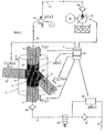
- FIG. 3 An arrangement for internal pressure-assisted forming with such a pressure control is now illustrated very schematically in FIG.
- FIG. 3 just like in FIG. 7 to be explained - components corresponding to the respective components of FIG. 1 are designated with the same reference numerals.
- a movable tool part 13 for counter-holding is arranged in the tool cavity 7 to support the bulged workpiece part 12, this movable or variable counter-holding tool part 13 being referred to below as a counter-holding stamp for the sake of simplicity.
- the counter-holding force of this counter-holding die 13 is indicated by Fg, whereas the pressing force of the pressing dies 3, 4 is indicated by Fp1 and Fp2.
- the internal pressure in the interior of the workpiece 1 is indicated by pi, this internal pressure pi being controlled as a function of the path s of the press rams 3, 4 during the course of the process. Accordingly, the press rams 3, 4 are assigned in the drawing, not illustrated in more detail, of conventional design per se, so as to detect the path s of the press rams 3, 4 at any time.
- the internal pressure pi (s) is set with the aid of a pressure valve 14 which is arranged in a pressure medium discharge line 15 leading through the upper press ram 3, a control valve 16 being connected upstream of it and having two positions - filling or Presses - owns.
- a pressure medium supply line 17 runs through the other - lower - press ram 4, through which a controllable pump 18, which is driven by a motor 19, supplies the liquid pressure medium - preferably simply water - to the interior of the workpiece 1.
- a check valve 20 is furthermore arranged in the pressure medium supply line 17.
- the shape of the die or tool 2 also called shape, can be seen in more detail, whereby it can be seen that the externally circular tool 2 has an elongated interior or molding space 21 of a square shape Cross-section, for the workpiece 1 having a square cross-section, and furthermore the cavity 7 of a rectangular cross-section branching therefrom for the bulge or branch 12 of the workpiece 1 to be produced.
- a blank ie a hollow profile with a square cross-section, from which the workpiece 1 with the branch 12 is to be formed, is inserted into the tool 2, after which the two press rams 3, 4 are brought into engagement with the end faces of the blank, a tight seal on these end faces being brought about with the aid of the press rams 3, 4.
- the press rams 3, 4 can be stepped on their end faces on the outer circumference, ie have step-shaped shoulders, which in particular have a height in the range from 5% to 100% of the mean wall thickness of the blank, and with which the material of the blank during pressing is plasticized, whereby a metallic seal is brought about.
- the pump 18 is switched on in order to supply pressure medium, in particular water, to the interior of the blank via the pressure medium supply line 17.
- the valve 16 on the outlet side is in the "fill" position as shown, it being easy to determine in this position when the pressure medium exits on the outlet side (as is schematically illustrated in FIG. 3 with the outlet line 22).
- the control valve 16 is then adjusted upward into its “pressing” position, as shown in FIG. 3, in which a connection to the pressure valve 14 instead of to the outlet line 22 is established on the outlet side.
- the pressure of the pressure medium is now increased with the aid of the pump 18, and the pressing process can begin by driving the press rams 3, 4 with the pressing force Fp1 or Fp2. This results in the aforementioned tight sealing of the end faces of the blank by the press rams 3, 4, by plasticizing the blank material, and during the pressing, the internal pressure pi of the pressure medium is increased by the upsetting process.
- the internal pressure pi (s) is continuously adjusted with the help of the pressure valve 14, starting with a preload pressure at the beginning of the pressing, a pressure increase to approximately twice the preload pressure can be provided, after which, for example, a linear pressure increase in a next section of the process about ten times the pressure value - up to about the middle of the entire pressing process, ie half way the press ram 3, 4 - is provided; the internal pressure pi is then kept constant, for example, at this maximum value that has now been reached.
- the bulge or branch 12 is produced, with the counter-punch 13 being held here with a counter-holding force Fg, which is preferably also controlled as a function of the path, in order to prevent the bulge 12 from bursting or bursting.
- FIG. 6 shows a diagram of the internal pressure pi (in bar) over the path s (in mm) of the press rams 3, 4, the internal pressure pi generally being controlled as a function of the path as set out above.
- a preload pressure pv of, for example, 130 bar is set at the beginning of the pressing process, and when the pressing begins, the internal pressure pi increases to a value pa of e.g. 250 bar, which is kept constant up to a press ram path s of 7.5 mm (phase of the molding on the punch 13 and beginning bulge with small strains).
- a workpiece 1 'with two branches 12', 12 '' can also be produced with a fundamentally similar internal pressure curve as shown in FIG. 6, as is illustrated in the diagram of FIG.
- the tool 2 ' has two cavities 7', 7 '' for the bulges or branches 12 ', 12' ', with corresponding counter-holding punches 13', 13 '' as variable tool parts in these cavities 7 ', 7' ' a contact pressure Fg1 (s) or Fg2 (s) are kept movable.
- the press rams 3, 4 are applied to the workpiece 1 'with a pressing force Fp1 or Fp2.
- a supply line 23 is provided, to which the pressure medium supply line 17 is connected via a directional control valve 24 and on the one hand via the pump 18 or on the other hand directly via a check valve 25.
- a pressure valve 14 ' is in turn connected to the pressure medium discharge line 15, which in the present case is controlled via a hydraulic control circuit Pump 26 and a control line 27, in which a check valve 28 is received, can be adjusted in pressure.
- control and regulating unit 30 which controls the process water preload pump 18 and the pump 26 which can be adjusted with regard to the outlet pressure in the control circuit for the pressure valve 14 'for the purpose of setting the respective internal pressure pi.
- Input variables for the control and regulating unit 30 are the path s of the press rams 3, 4 (it is usually sufficient to take the path of a press ram, for example 3, and feed them to the unit 30) and the internal pressure pi (see also for safety reasons) ).
- a control or regulation can be provided as desired, and accordingly the sizes Fp1, Fp2, Fg1 and Fg2 according to Fig. 7 are both recorded and set, e.g. simply path-dependent or with an additional readjustment (actual value-target value comparison), as will be explained in more detail below with reference to the flow diagrams from FIGS. 8 to 10.
- the unit 30 could be a PLC (programmable logic controller) unit, with which the pressing pressures (pressing forces Fp1, Fp2, Fg1, Fg2) and in particular the internal pressure pi can be set simply as a function of the path.
- PLC programmable logic controller
- FIG. 8 A corresponding flow chart is shown in FIG. 8, which includes such a simple path-dependent pressure control and counterforce control.
- the workpiece 1 ' is filled in block 33 until the pressure medium emerges at the outlet of the pressure valve 14'.
- the valves v1 and v2 are set in accordance with block 35 in FIG. This starts the actual pressing process, during which the path s of the press ram 3, 4 is measured, see Block 36 in Fig. 8.
- the pressure relief valve 14 'for the internal pressure pi is continuously set depending on the path s, block 37 in FIG. 8.
- block 39 it is queried cyclically whether the press ram path s has reached the end value for it, ie whether the pressing process can be ended or not. If this is not the case, the system returns to block 36, etc. at 40, and a new path measurement, pressure relief valve position, etc. is carried out 8 is indicated at 41.
- FIG. 9 illustrates a somewhat modified process flow compared to FIG. 8, in that an internal pressure-dependent regulation for the counter-stamping forces Fg1 and Fg2 takes place.
- Steps 31 to 37 are the same as in the flow chart according to FIG. 8, so that a new description of the same can be omitted.
- step 37 setting the internal pressure pi
- Fg1 and Fg2 i.e.
- a setpoint Fg1 (pi) and a setpoint Fg2 (pi) are defined and compared with the actual value Fg1ist or Fg2ist.
- the valves for actuating the counterhold punches 13 'or 13' 'are set block 43 in Fig. 9. Then in block 39 it is again queried whether the press punches have already reached their end of travel, and if not, the process returns to block 39, if so, the end 41 is reached.
- steps 31 to 35 which in turn are identical, are followed by a modified measuring step at 36 ', where not only the ram path s but also the ram forces Fp1 and Fp2 are measured.
- valves for the counter-holding punches 13 'or 13' '(Fg1, Fg2) are again set, analogously to FIG.
- the rest of the procedure is the same as that of Fig. 8 or 9.
- FIG. 11 schematically shows a device with a tool 2 without variable tool parts (counter-punch) in a cavity 7, for example a hemispherical bulge 12 on the workpiece 1 'during the pressing using the press punches 3, 4.
- a heat treatment of the blank to be pressed is desired before the pressing process - as a rule, such a heat treatment is preferred for soft annealing - the duration and the degree of heat treatment (temperature) naturally depend on the respective blank, in particular on the respective material.
- heat treatment will have to be carried out in such a way that the blank is sufficiently long, e.g. 1 to 2 hours, heated to a few 100 ° C in an annealing furnace, after which it is allowed to cool in air; Before the so annealed material would lose ductility again due to the removal of alloy components to the grain boundaries, the pressing process - e.g. about 2 or 3 hours after the heat treatment.
- the upright arrangement of the tool shown in FIGS. 3 and 7 with the supply of the pressure medium from below has the advantage that when filling, air bubbles or gas bubbles in general can rise upwards, so that the interior of the blank or workpiece 1 or 1 ' can be filled without gas bubbles can.
- Adequate lubrication is also important when pressing, particularly in places with a strong curvature where the material has to flow around tight radii or into tight radii.
- Appropriate lubricant application is therefore particularly important on edges - including the blank. In particular, it is advantageous to apply around 50% more lubricant in the edge area.
- a hollow profile blank with a square cross-section was pressed from an AlMgSi 0.5 material, the dimensions of the blank being as follows: external dimensions 30 ⁇ 30 mm 2 , wall thickness 2 mm, corner radius 2 mm, length 155 mm.
- the tensile strength for AlMgSi 0.5 is approx. 200 N / mm 2 .
- the blank Before being pressed, the blank was heated to 400 ° C. in an annealing furnace for 100 minutes and then cooled in air. The press processing took place after approx. 3 hours. For this purpose, a preload pressure of 130 bar was set (at the beginning of the pressing process), and the maximum internal pressure that was reached in the second half of the process phase, where large expansions of the material of the workpiece were required, was 2000 bar.
- the pressing speed was 5 mm / s, and the counter-holding force of the one counter-holding die for the production of a workpiece with a branch, square as the initial profile, was 10 kN.
- the workpiece produced was a T-piece, similar to that shown in FIG. 3, with a branch length of 53 mm (measured against the rear wall), and the workpiece had a final length of 90 mm. In the area of the junction, the corner radius was 3 mm.
- a wide variety of conventional pressure valve types can be used as the pressure valve 14 and 14 ', in particular, in addition to the hydraulically operated pressure valve 14' shown in FIG. 7, also electromagnetically operated pressure valves.
- the control and regulating unit 30 can furthermore be implemented in a conventional manner with corresponding electrical circuits, such as, in particular, A / D converters, D / A converters, comparators and / or microprocessors.
- electrical circuits such as, in particular, A / D converters, D / A converters, comparators and / or microprocessors.
- Such regulating and control units are basically known per se in conventional presses, so that a detailed explanation can be omitted here.
Landscapes
- Engineering & Computer Science (AREA)
- Mechanical Engineering (AREA)
- Physics & Mathematics (AREA)
- Fluid Mechanics (AREA)
- Shaping Metal By Deep-Drawing, Or The Like (AREA)
- Superconductors And Manufacturing Methods Therefor (AREA)
- Forging (AREA)
Abstract
Description
Die Erfindung betrifft ein Verfahren zur innendruckgestützten Umformung von metallischen Hohlprofilen in Werkzeugen zu mit Ausbuchtungen, Aushalsungen, Abzweigungen oder dergl. versehenen Werstücken, wobei dem Inneren eines im Werkzeug angebrachten Rohlings, der an seinen Stirnseiten mit zumindest einem beweglichen Preßstempel und einem stationären Gegenhalte-Werkzeugteil, vorzugsweise mit zwei beweglichen Preßstempeln, in Eingriff gebracht wird, ein flüssiges Druckmittel zugeführt wird, der Rohling mit Hilfe des oder der Preßstempel(s) unter Ausbauchen in zumindest einen Hohlraum im Werkzeug hinein gepreßt wird und der Druck des Druckmittels im Inneren des durch den Preßstempel und stationären Gegenhalte-Werkzeugteil bzw. die Preßstempel abgeschlossenen Rohlings in Abhängigkeit vom Prozeßfortschritt beim Pressen, vorzugsweise in Abhängigkeit vom Preßstempel-Weg, gesteuert wird.The invention relates to a method for the internal pressure-assisted forming of hollow metal profiles in tools for workpieces provided with bulges, neckings, branches or the like. The inside of a blank attached to the tool, the end faces of which have at least one movable pressing die and a stationary counter-holding tool part , preferably with two movable press rams, is brought into engagement, a liquid pressure medium is supplied, the blank is pressed with the help of the press ram (s) with bulging into at least one cavity in the tool and the pressure of the pressure medium inside the through the Press ram and stationary counter-tool part or the ram closed blank depending on the process progress during pressing, preferably depending on the ram path is controlled.
Weiters bezieht sich die Erfindung auf eine Vorrichtung zur Durchführung dieses Verfahrens, mit einem Werkzeug sowie einer an eine Druckmittelquelle angeschlossene Druckmittelzuführeinrichtung, die eine Druckmittel-Zuführleitung durch den bzw. einen der Preßstempel oder gegebenenfalls durch den stationären Gegenhalte-Werkzeugteil umfaßt, und der eine Druckeinstelleinrichtung zugeordnet ist, sowie auf ein durch das erfindunggemäße Verfahren erhaltene Werkstück.Furthermore, the invention relates to a device for performing this method, with a tool and a pressure medium supply device which is connected to a pressure medium source and which comprises a pressure medium supply line through the or one of the press rams or, if appropriate, through the stationary counter-holding tool part, and which has a pressure setting device is assigned, and to a workpiece obtained by the method according to the invention.
Es ist bekannt, innendruckgestützte Umformverfahren für rohrförmige Werkstücke aus duktilen Stählen, mit kreisförmigem Querschnitt, einzusetzen, um aus diesen rohrförmigen Rohlingen T-Stücke herzustellen. Bei dieser Art von Umformtechnik wird das Werkstück durch ein vorgegebenes Werkzeug (auch Matrize oder Außenform genannt) von außen her und durch hohe Druckmittel-Drücke von der Innenseite her gestützt. Die Verformung wird dabei mit Hilfe von Preßstempeln durchgeführt, und im Zuge dieser Verformung oder dieses Verpressens werden Teile des rohrförmigen Rohlings in einen Hohlraum des Werkzeugs ausgebaucht und hineingeformt. Beispielsweise zeigen die FR-A-1 048 482 und die US-A-3 350 905 derartige Umformtechniken, wobei gemäß der FR-A-1 048 482 der Druck des Druckmittels im Inneren des Werkstücks gleich dem Druck, mit dem die Preßstempel beaufschlagt werden, gehalten oder aber mit Hilfe eines Reduzierventils auf einen demgegenüber kleineren Wert beschränkt wird; gemäß der US-A-3 350 905 kann dagegen dieser Innendruck mit Hilfe von festen Steuerkurven, die von einer Rolle zwecks Ansteuerung einer Druckmittelpumpe abgetastet werden, abhängig von der Position der Preßstempel geändert werden, um einen überhöhten Innendruck und damit eine Zerstörung des Werkstückes während des Fortschreitens des Umformvorganges zu vermeiden. Aus der EP-A-36 365 sind schließlich ein Verfahren und eine Vorrichtung der eingangs angeführten Art bekannt, wobei im Hinblick auf immer vorhandene Gefügeunregelmäßigkeiten und Wanddickenunterschiede in den Ausgangsrohren ein möglichst geringer Ausschuß bei der Druckumformung dadurch erreicht werden soll, daß zumindest einmal bei einem vorherbestimmten Wert der Längsverdichtung, also des Preßstempel-Weges, der Druck des Druckmittels im Werkstück-Inneren und/oder die Querverformung, also der Weg eines Gegenhalte-Stempels im Werkzeug-Hohlraum, in den hinein das Werkstück ausgebaucht wird, gemessen wird bzw. werden und unabhängig vom Meßergebnis das Verhältnis Innendruck zu Längsverdichtung neu festgelegt wird, und zwar auf Basis von zuvor an verschiedenen Rohlingstypen durchgeführten Experimenten.It is known to use internal pressure-based forming processes for tubular workpieces made of ductile steels with a circular cross section in order to produce T-pieces from these tubular blanks. In this type of forming technology, the workpiece is supported from the outside by a specified tool (also called a die or external shape) and from the inside by high pressure medium pressures. The deformation is carried out with the aid of press rams, and in the course of this deformation or pressing, parts of the tubular blank are bulged into a cavity of the tool and molded into it. For example, FR-A-1 048 482 and US-A-3 350 905 show such forming techniques, wherein according to FR-A-1 048 482 the pressure of the pressure medium inside the workpiece is equal to the pressure with which the press rams are applied , held or limited to a smaller value with the help of a reducing valve; according to US-A-3 350 905, on the other hand, this internal pressure can be changed with the aid of fixed control cams, which are scanned by a roller for the purpose of actuating a pressure medium pump, depending on the position of the press rams in order to avoid excessive internal pressure and thus destruction of the workpiece as the forming process progresses. Finally, EP-A-36 365 discloses a method and a device of the type mentioned at the outset, with regard to the structural irregularities and wall thickness differences in the outlet pipes which are always present, the least possible rejection of the pressure deformation is to be achieved in that at least once in one Predetermined value of the longitudinal compression, i.e. the press ram path, the pressure of the pressure medium in the interior of the workpiece and / or the transverse deformation, i.e. the path of a counter-ram in the tool cavity into which the workpiece is bulged, is measured and regardless of the measurement result, the ratio of internal pressure to longitudinal compression is redefined, based on experiments previously carried out on different blank types.
Die bekannten Techniken können bisher jedoch nur für ganz bestimmte Werkstücke bzw. Rohlinge, insbesondere mit Kreisquerschnitt, und überdies nur, wenn sie aus ganz bestimmten Werkstoffen bestehen, nämlich duktilen Stählen, mit einer Sprödbruchzähigkeit um 100 MN·m-3/2, angewandt werden; bei anderen Rohlingen, mit nicht-runden Querschnitten, etwa quadratischen, rechteckigen Querschnitten, und/oder bei anderen Werkstoffen, wie etwa hochfesten Aluminiumlegierungen (die eine Sprödbruchzähigkeit von unter 30 MN·m-3/2 aufweisen), ist eine derartige innendruckgestützte Umformung bisher wegen der geringen Duktilität bzw. wegen der Schwierigkeiten, die beim Fließen des Werkstoffmaterials in Formteile großer Krümmung (d.h. mit kleinem Krümmungsradius) auftreten, praktisch nicht möglich gewesen, da es hier zum frühzeitigen Reißen des Werkstoffes kommt.However, the known techniques have hitherto only been able to be used for very specific workpieces or blanks, in particular with a circular cross section, and moreover only if they consist of very specific materials, namely ductile steels with a brittle fracture toughness of 100 MN.m -3/2 ; In the case of other blanks with non-round cross-sections, for example square, rectangular cross-sections, and / or in the case of other materials, such as high-strength aluminum alloys (which have a brittle fracture toughness of less than 30 MN.m -3/2 ), such internal pressure-supported forming has hitherto been the case because of the low ductility or because of the difficulties that occur when the material material flows into molded parts with a large curvature (ie with a small radius of curvature), this was practically impossible since the material breaks prematurely.
Es ist somit Aufgabe der Erfindung, hier Abhilfe zu schaffen und eine Technik vorzusehen, mit der auch Rohlinge mit unrundem Querschnitt bzw. aus derartigen spröden Materialen, wie etwa hochfesten Alumiumimlegierungen, einem innendruckgestützen Umformverfahren unterzogen werden können, um so T-Stücke, Anschlußstücke, Verzweigungsstücke, Knotenstücke und dergl. herstellen zu können. Dabei wird insbesondere angestrebt, Werkstücke zu erzeugen, die in den entsprechenden Bereichen einen Oberflächenkrümmungsradius aufweisen, der kleiner ist als 10 % des Ersatzdurchmessers Ders des Außenquerschnittes Q dieses Rohlinges, wobei dieser Ersatzdurchmesser ![]()
![]()
Das erfindungsgemäße Verfahren der eingangs angeführten Art ist demgemäß dadurch gekennzeichnet, daß in Prozeßphasen mit kleinen Dehnungen des Werkstoffes der Druck des Druckmittels so eingestellt wird, daß die aus dem räumlichen Spannungszustand im Werkstück gebildete Vergleichsspannung im wesentlichen gerade die Formänderungsfestigkeit des Werkstoffes erreicht, wogegen in Prozeßphasen mit großen Dehnungen der Druck des Druckmittels erhöht wird, um die Bruchdehnung des Werkstoffs durch Absenken der mittleren Spannung ausreichend hinaufzusetzen. Mit einer derartigen Drucksteuerung des Drucks des - flüssigen - Druckmittels im Inneren des Rohlings während des Preßvorganges kann je nach Art und Dimension des herzustellenden Werkstückes, insbesondere je nach Wandstärke des Rohlings, nach Querschnitt des Rohlings usw., das Fließen des Materials ohne Reißen gewährleistet werden, wobei die Innendruckführung beim Fließen des Materials in Formteile großer Krümmung von entscheidender Bedeutung ist. Dabei gilt allgemein, daß der Innendruck umso höher einzustellen ist, je größer die Wandstärken des Rohlings sind, und/oder je kleiner die Formkrümmungsradien sind, denen beim Verformen des Rohlings gefolgt werden muß. Auch bei kleinen Werkstück- bzw. Rohling-Durchmessern ist der Innendruck vergleichsweise hoch zu bemessen. Grund hierfür sind die in solchen Fällen auftretenden großen Vergleichsdehnungen (nach Tresca oder Mises) an einzelnen Punkten des Werkstückes, so daß durch Absenkung des hydrostatischen Spannungsanteiles (Vergrößerung des hydrostatischen Druckes) die mögliche Vergleichsbruchdehnung angehoben werden muß (Druckspannungen werden negativ gerechnet).The inventive method of the type mentioned is accordingly characterized in that in process phases with small expansions of the material, the pressure of the pressure medium is set so that the comparative stress formed in the workpiece from the spatial stress state essentially reaches the deformation resistance of the material, whereas in process phases with large expansions, the pressure of the pressure medium is increased in order to increase the elongation at break of the material sufficiently by lowering the mean stress. With such a pressure control of the pressure of the - liquid - pressure medium inside the blank during the pressing process, depending on the type and dimension of the workpiece to be produced, in particular depending on the wall thickness of the blank, on the cross section of the blank, etc., the flow of the material can be ensured without tearing , whereby the internal pressure guide is of crucial importance when the material flows into molded parts with a large curvature. It generally applies that the internal pressure is to be set higher, the greater the wall thickness of the blank, and / or the smaller the radii of curvature which must be followed when the blank is deformed. Even with small workpiece or blank diameters, the internal pressure must be dimensioned comparatively high. The reason for this is the large comparative strains that occur in such cases (according to Tresca or Mises) at individual points on the workpiece, so that by lowering the hydrostatic stress component (increase in hydrostatic pressure) the possible comparative fracture elongation must be increased (compressive stresses are calculated negatively).
Dabei ist es bei Anwendung der erfindungsgemäßen Technik erstmals möglich, vor allem dünnwandige, hochfeste Aluminiumteile nicht-runden Querschnitts mit praktisch beliebig geformten Ausbuchtungen herzustellen. Derartige Werkstücke können beispielsweise als Knotenstücke bei sogenannten "Spaceframes" (Rahmenkonstruktionen aus Aluminium oder Aluminiumlegierungen, die mit mit Aluminiumplatten beplankt werden) in der Fahrzeugkarosserietechnik verwendet werden, wobei dann gerade oder gebogene Stäbe oder Profile in Knotenstücke eingeführt und darin verschweißt oder verklebt werden.When using the technique according to the invention, it is possible for the first time to produce, in particular, thin-walled, high-strength aluminum parts with a non-round cross-section with bulges of virtually any shape. Such workpieces can be used, for example, as nodes in so-called "space frames" (frame structures made of aluminum or aluminum alloys which are covered with aluminum plates) in vehicle body technology are used, in which case straight or curved rods or profiles are inserted into knot pieces and welded or glued therein.
Mehr im Detail wird die Steuerung des Druckes des Druckmittels während der Umformung derart erfolgen, daß in Prozeßphasen, in denen ein beginnendes Ausbauchen, gegebenenfalls ein Anformen des Werkstückes an variable (bewegliche) Werkzeugteile, erfolgt und die auftretenden Vergleichsdehnungen klein sind, der Druck zusammen mit den durch die Preßstempel hervorgerufenen Spannungen im Werkstück auf den einachsigen Spannungszustand durch Bildung der sog. Vergleichsspannung (nach Tresca oder Mises) modellmäßig ausgebildet die Formänderungsfestigkeit des Werkstoffes erreicht (bei den gegebenen Spannungsverhältnissen der nächste Punkt auf der sog. Hyperfließfläche im Spannungsraum, welche bei plastischer Verformung gemäß der Fließbedingung von Tresca (schiefes Sechskantprisma) oder Mises (schiefer elliptischer Zylinder) alle während des Fließens denkbaren Spannungszustände umfaßt); dagegen wird in Prozeßphasen, in denen große Dehnungen auftreten, beispielshalber zum Nachschub von Material in ausgeformte Werkstückteile, der Druck zu jedem Zeitpunkt mindestens so groß gehalten, daß der insgesamt im Werkstück aus dem räumlichen Spannungszustand gebildete resultierende hydrostatische Spannungsanteil (negativ), bezogen auf die Formänderungsfestigkeit gemäß der entsprechenden Werkstoffkennlinie, eine Bruchdehnung besitzt, die größer ist als die maximal am Werkstück in diesem Zeitpunkt auftretende Vergleichsdehnung.The pressure of the pressure medium during the forming process will be controlled in more detail in such a way that in process phases in which an initial bulging, possibly a shaping of the workpiece onto variable (movable) tool parts, and the occurring comparative strains are small, the pressure together with The stresses in the workpiece caused by the press ram to the uniaxial stress state by forming the so-called comparative stress (according to Tresca or Mises) reaches the deformation resistance of the material (given the stress conditions, the next point on the so-called hyper flow surface in the stress space, which in plastic Deformation according to the flow condition of Tresca (oblique hexagonal prism) or Mises (oblique elliptical cylinder) includes all conceivable stress states during flow); in contrast, in process phases in which large strains occur, for example to replenish material in molded workpiece parts, the pressure is kept at least at such a time at all times that the resulting hydrostatic stress component (negative), which is formed in the workpiece from the spatial state of tension (negative), related to the Strain resistance according to the corresponding material characteristic, has an elongation at break that is greater than the maximum comparative elongation occurring on the workpiece at this point in time.
Im Rahmen der erfindungsgemäßen Drucksteuerung während des Verpressens der Rohlinge hat es sich für einen effektiven Preßvorgang als besonders vorteilhaft erwiesen, wenn das Druckmittel am Beginn des Preßvorganges auf einen niedrigen Überdruck, z.B. in der Größenordnung von 300 bis 600 bar, und gegen Ende des Preßvorganges auf den Maximalwert, beispielsweise in der Größenordnung von einigen kbar, gebracht wird. Dabei kann der Innendruck des Rohlings, d.h. der Druck des Druckmittels, beispielsweise während ungefähr der ersten Hälfte des Preßvorganges (d.h. der Hälfte des Weges des oder der Preßstempel) mehr oder weniger konstant auf ungefähr einem Drittel bis zu einem Fünftel des gegen Ende des Preßvorganges vorgesehenen Maximalwertes gehalten werden, und ungefähr ab der Hälfte des Preßvorganges kann dann der Innendruck allmählich, beispielsweise linear, bis zum Maximaldruck zum Ende des Preßvorganges hin gesteigert werden. In jedem Fall muß während des anfänglichen Ausbauchens durch den eingestellten Innendruck die Vergleichsspannung resultierend aus Innendruck und den Spannungen aus den Preßkräften und Reibungskräften die Formänderungsfestigkeit des Materials erreichen.In the context of the pressure control according to the invention during the pressing of the blanks, it has proven to be particularly advantageous for an effective pressing process if the pressure medium at the beginning of the pressing process is at a low excess pressure, for example in the order of 300 to 600 bar, and towards the end of the pressing process the maximum value, for example in the order of a few kbar, is brought. The internal pressure of the blank, ie the pressure of the pressure medium, for example during approximately the first half of the pressing process (ie half of the path of the ram or the ram) can be more or less constant at about one third to one fifth of that provided towards the end of the pressing process Maximum values can be kept, and then from about half the pressing process the internal pressure can be increased gradually, for example linearly, up to the maximum pressure at the end of the pressing process. In any case, during the initial bulging due to the set internal pressure, the reference stress resulting from the internal pressure and the stresses from the pressing and frictional forces must reach the material's resistance to deformation.
Weiters hat es sich als günstig erwiesen, wenn das Druckmittel während des Preßvorganges auf einen Maximaldruck von mindestens 80% der Zugfestigkeit des Werkstoffes des Rohlings gebracht wird. An sich ist bei der Festlegung des Wertes für den Maximaldruck selbstverständlich nicht nur der Werkstoff selbst, sondern auch die Materialstärke sowie auch der Querschnitt des Werkstückes zu berücksichtigen, wie dies bereits vorstehend erwähnt worden ist. Die Drucksteuerung hängt im Detail von der Art und Form des herzustellenden Werkstückes ab, und es kann hier mit Vorteil vorgesehen werden, daß der Druck des Druckmittels in Preßphasen, in denen der Werkstoff des Rohlings kleine Krümmungsradien des Werkzeugs umfließt, je nach Wandstärke auf 5%-40% des Maximaldrucks beim Pressen eingestellt wird (die Vergleichsspannung erreicht die Formänderungsfestigkeit). Der maximale Innendruck wird dagegen außerhalb dieser Phasen erreicht.Furthermore, it has proven to be advantageous if the pressure medium is brought to a maximum pressure of at least 80% of the tensile strength of the material of the blank during the pressing process. As such, when determining the value for the maximum pressure, not only the material itself, of course, but also the material thickness and also the cross section of the workpiece must be taken into account, as has already been mentioned above. The pressure control depends in detail on the type and shape of the workpiece to be produced, and it can advantageously be provided here that the pressure of the pressure medium in pressing phases in which the blank material flows around small radii of curvature of the tool, depending on the wall thickness, to 5%. -40% of the maximum pressure during pressing is set (the reference stress reaches the deformation resistance). The maximum internal pressure is reached outside of these phases.
Für die erfindungsgemäß herzustellenden Werkstücke bzw. zu verarbeitenden Werkstoffe (die eine geringere Duktilität als duktile Stähle aufweisen) ist es sodann von ganz besonderem Vorteil, wenn das Druckmittel bereits vor dem Pressen des Rohlings auf einen erhöhten Vorspanndruck, vorzugsweise 5%-20%, insbesondere ungefähr 10%, des beim Pressen erreichten Maximaldrucks, z.B. auf einen Wert in der Größenordnung von 100 bis 1000 bar, gebracht wird. Eine derartige Vorspannung des Druckmittels ist insbesondere für das anfängliche problemfreie Ausbauchen des Rohlings von Bedeutung, wobei der Wert des Vorspanndruckes abhängig von der Knickspannung des zu verformenden Werkstoffes gewählt wird; insbesondere ist der Innendruck so festzulegen, daß kein Einknicken an der Stelle der herzustellenden Ausbauchung erfolgt, was bei einer fehlenden Vorspannung des Druckmittels insbesondere bei Verarbeitung von im Verhältnis zu den übrigen Abmessungen des Hohlprofils kleinen Wandstärken passieren könnte.For the workpieces or materials to be processed according to the invention (which have a lower ductility than ductile steels), it is then of particular advantage if the pressure medium is already at an increased preload pressure, preferably 5% -20%, in particular before the blank is pressed about 10% of the maximum pressure reached during pressing, e.g. is brought to a value in the order of 100 to 1000 bar. Such prestressing of the pressure medium is particularly important for the initial problem-free bulging of the blank, the value of the prestressing pressure being selected as a function of the buckling stress of the material to be deformed; in particular, the internal pressure is to be determined in such a way that there is no buckling at the point of the bulge to be produced, which could happen if the pressure medium is not preloaded, in particular when processing wall thicknesses which are small in relation to the other dimensions of the hollow profile.
Um während des Preßvorganges eine exakte Drucksteuerung zu ermöglichen, ist es auch vorteilhaft, wenn der Rohling vor dem Preßvorgang Gaseinschlüsse-frei mit dem Druckmittel gefüllt wird, und wenn das Druckmittel durch eine Pumpe auf einen erhöhten Druck gebracht wird. Würden sich im - flüssigen - Druckmittel Gaseinschlüsse befinden, so wäre aufgrund der Komprimierung und des Expandierens der Gaseinschlüsse die jeweilige gewünschte Druckerhöhung bzw. -reduktion nicht zu erzielen und damit die angestrebte exakte Drucksteuerung beeinträchtigt.To ensure exact pressure control during the pressing process enable, it is also advantageous if the blank is filled with the pressure medium free of gas inclusions before the pressing process, and if the pressure medium is brought to an increased pressure by a pump. If there were gas inclusions in the - liquid - pressure medium, the compression and expansion of the gas inclusions would not make it possible to achieve the desired pressure increase or reduction and thus impair the exact pressure control sought.
Um auch aus anderer Sicht, nämlich der Sicht des Verschließens des Rohlings während des Preßvorganges, um den erhöhten Innendruck sicherzustellen, die gewünschte exakte Drucksteuerung zu gewährleisten, ist eine möglichst gute Abdichtung des Rohlings an dessen Stirnseiten erforderlich. Beispielsweise können zum dichten Abschließen des Rohlings Preßstempel mit stufenförmigen Absätzen an den Stirnseiten-Rändern eingesetzt werden, die eine Höhe von 5%-100% der mittleren Wandstärke des Rohlings aufweisen, und mit denen der Werkstoff des Rohlings zur Herbeiführung einer metallischen Dichtung plastifiziert wird.In order to ensure the desired exact pressure control from another point of view, namely the point of view of closing the blank during the pressing process, in order to ensure the increased internal pressure, the blank must be sealed as well as possible on its end faces. For example, press seals with step-shaped shoulders on the front edges can be used to seal the blank tightly, which have a height of 5% -100% of the mean wall thickness of the blank, and with which the material of the blank is plasticized to produce a metallic seal.
Bevorzugt werden die Rohlinge vor dem Preßvorgang einer Wärmebehandlung unterzogen, um dadurch den Werkstoff duktiler zu machen. Dieser weist dann aufgrund seiner Gefügestruktur eine deutlich erhöhte Bruchdehnung auf. In diesem Zusammenhang ist eine vorteilhafte Ausführungsform des erfindungsgemäßen Verfahrens dadurch gekennzeichnet, daß im Fall von Rohling-Werkstoffen, die Auslagerungen von Legierungsbestandteilen an die Korngrenzen aufweisen, insbesondere von hochfesten Aluminiumlegierungen, vor dem Preßvorgang eine Wärmebehandlung derart durchgeführt wird, daß durch Einlagerung dieser Legierungsbestandteile in die Korngitter die Duktilität des Werkstoffs erhöht wird, und daß der Preßvorgang innerhalb eines vorgegebenen Zeitfensters, z.B. 1h bis 4h nach der Wärmebehandlung, jedoch bevor es zu einer erneuten Auslagerung der Legierungsbestandteile an die Korngrenzen kommt, durchgeführt wird. Beispielsweise hat sich gezeigt, daß es von Vorteil ist, wenn Rohlinge aus AlMgSi-Legierungen bei ca. 400°C ungefähr 100 min lang in einem Glühofen erwärmt, anschließend in Luft gekühlt und ca. 3h nach Ende der Glühofen-Wärmebehandlung verpreßt werden. Die Zeitdauer des eigentlichen Preßvorganges liegt dabei im Bereich von einer oder einigen wenigen Minuten, oft auch unter einer Minute, einschließlich des vorhergehenden Füllens mit dem Druckmittel. Die reine Preßzeit kann daher manchmal auch bloß 20 s bis 30 s betragen.The blanks are preferably subjected to a heat treatment before the pressing process, in order to thereby make the material more ductile. Because of its microstructure, it then has a significantly higher elongation at break. In this context, an advantageous embodiment of the method according to the invention is characterized in that, in the case of blank materials which have alloy components at the grain boundaries, in particular high-strength aluminum alloys, a heat treatment is carried out before the pressing process in such a way that by storing these alloy components in the grain lattice increases the ductility of the material, and that the pressing process is carried out within a predetermined time window, for example 1 hour to 4 hours after the heat treatment, but before the alloy components are again outsourced to the grain boundaries. For example, it has been shown that it is advantageous if blanks made of AlMgSi alloys are heated at about 400 ° C. for about 100 minutes in an annealing furnace, then cooled in air and pressed in about 3 hours after the end of the annealing furnace heat treatment. The duration of the actual pressing process is in the range of one or a few minutes, often less one minute, including the previous filling with the pressure medium. The pure pressing time can therefore sometimes be as little as 20 s to 30 s.
Bei manchen herzustellenden Werkstücken ist es denkbar, die herzustellende Ausbuchtung einfach in einen entsprechenden Hohlraum in der Matrize oder im Werkzeug hineinzuverformen, d.h. auszubauchen; für einen exakten Formvorgang, insbesondere bei längeren Ausbuchtungen oder Abzweigungen, wird jedoch beim Verpressen des Rohlings in dem (jeweiligen) Werkzeug-Hohlraum, in den das Material des Rohlings hineinverformt wird, mit einem variablen Gegenhalte-Werkzeugteil, der eine Querschnittsform entsprechend dem (jeweiligen) auszubauchenden Teil aufweist, gegengehalten, und es ist hier erfindungsgemäß von besonderem Vorteil, wenn mit dem (jeweiligen) variablen Werkzeugteil druck-und/oder weggesteuert gegengehalten wird und die dabei in das Werkstück eingeleitete Kraft so bemessen wird, daß die insgesamt im Werkstück auftretende mittlere Spannung (der hydrostatische Spannungsanteil) soweit vermindert wird, daß die dadurch festgelegte Bruchdehnung größer wird als die größte im betreffenden durch den variablen Werkzeugteil abgestützten Werkstückteil auftretende Dehnung. Die exakte Druck- oder Wegführung des oder der variablen Gegenhalte-Werkzeugteile zur Abstützung ausgebuchteter Werkstückteile ist umso wichtiger, je spröder der Werkstoff und je kleiner die Wandstärke ist. Die Gegenstützung erzeugt in der anliegenden Außenfaser des Werkstückes einen hydrostatischen Spannungsanteil, der die mögliche, ausnützbare Bruchdehnung (insbesondere bei spröden Werkstoffen) entscheidend erhöht, so daß die in diesen Bereichen auftretenden größten Vergleichsdehnungen kleiner als die Bruchdehnung werden. Auf diese Weise wird ein Bersten des Werkstückes verhindert. Ein derartiges Gegenhalten ist insbesondere dann von Vorteil, wenn der Rohling eine Wandstärke kleiner als 10% des Ersatzdurchmessers Ders (wie oben definiert) aufweist bzw. wenn Werkstoffe mit einer Sprödbruchzähigkeit kleiner als 50 MN·m-3/2 bzw. Werkstoffe mit einer Zugfestigkeit Rm kleiner als 350 N/mm2 verwendet werden. Auch ist ein derartiges Gegenhalten günstig im Fall von bezüglich des Querschnittes ungleichmäßig herzustellenden Ausbuchtungen, die auf Teilen der Oberfläche kleine Krümmungsradien, insbesondere kleiner als 10% des genannten Ersatzdurchmessers Ders, aufweisen. Insbesondere ist nun hier erfindungsgemäß, wie vorstehend definiert, eine Steuerung der gegen das Werkstück gerichteten, von den variablen Gegenhalte-Werkzeugteilen übertragenen Kraft anzustreben, bei der in der am jeweiligen variablen Gegenhaltewerkzeug anliegenden Faser (der Außenfaser) des Werkstückes ein auf die Formänderungsfestigkeit bezogener hydrostatischer Spannungsanteil hervorgerufen wird, dessen Bruchdehnung gemäß der entsprechenden Werkstoffkennlinie in jedem Zeitpunkt größer ist als die größte dort auftretende Vergleichsdehnung.With some workpieces to be produced, it is conceivable to simply deform the bulge to be produced into a corresponding cavity in the die or in the tool, ie to bulge it; for an exact molding process, especially in the case of longer bulges or branches, however, when the blank is pressed into the (respective) tool cavity into which the material of the blank is deformed, a variable counter tool part is used, which has a cross-sectional shape corresponding to the (respective ) has to be bulged, held against it, and it is particularly advantageous here according to the invention if the (respective) variable tool part is held in a pressure-controlled and / or displacement-controlled manner and the force introduced into the workpiece is dimensioned such that the total occurring in the workpiece mean stress (the hydrostatic stress component) is reduced to such an extent that the elongation at break thereby determined becomes greater than the greatest strain occurring in the workpiece part in question supported by the variable tool part. The exact pressure or displacement of the variable counter-holding tool part (s) for supporting bulged workpiece parts is all the more important, the more brittle the material and the smaller the wall thickness. The counter support creates a hydrostatic stress component in the adjacent outer fiber of the workpiece, which increases the possible, exploitable elongation at break (especially in the case of brittle materials), so that the greatest comparative strains occurring in these areas become smaller than the elongation at break. This prevents the workpiece from bursting. Such holding back is particularly advantageous if the blank has a wall thickness less than 10% of the equivalent diameter D ers (as defined above) or if materials with a brittle fracture toughness less than 50 MN · m -3/2 or materials with a Tensile strength Rm less than 350 N / mm 2 can be used. Such countermeasures are also favorable in the case of bulges which are to be produced unevenly with respect to the cross section and which have small radii of curvature on parts of the surface, in particular less than 10% of the named replacement diameter D ers . In particular, according to the invention, as defined above, control of the force directed against the workpiece and transmitted by the variable counter-holding tool parts is to be aimed for, in the case of the fiber (the outer fiber) of the workpiece which is in contact with the respective variable counter-holding tool, a hydrostatic force related to the deformation resistance Stress component is caused, the elongation at break according to the corresponding material characteristic is greater than the greatest comparative elongation occurring there at any time.
Von Vorteil ist auch, wenn die durch den variablen Gegenhalte-Werkzeugteil aufzubringende Kraft zu jedem Zeitpunkt des Prozesses, insbesondere auch bereits bei Prozeßbeginn, mindestens 5% der durch den Innendruck auf den auszubauchenden Teil ausgeübten Kraft beträgt.It is also advantageous if the force to be exerted by the variable counter-holding tool part is at least 5% of the force exerted by the internal pressure on the part to be bulged out at any point in the process, in particular even at the start of the process.
Weiters hat es sich als günstig erwiesen, wenn im Fall der gleichzeitigen Herstellung von mehreren Ausbuchtungen, Abzweigungen oder dergl. und demgemäß der Verwendung von mehreren variablen druckgesteuerten Gegenhalte-Werkzeugteilen zusätzlich zu deren Drucksteuerung eine Wegüberwachung bzw. -messung durchgeführt wird, um bei ungleich schnellen Bewegungen der variablen Gegenhalte-Werkzeugteile ihre Drucksteuerung anzupassen.Furthermore, it has proven to be advantageous if, in the case of the simultaneous production of several bulges, branches or the like, and accordingly the use of several variable pressure-controlled counter-holding tool parts, a path monitoring or measurement is carried out in addition to their pressure control, in order to ensure that the speed is not the same Movements of the variable counter tool parts to adjust their pressure control.
In Formteilen großer Krümmung, z.B. abgerundeten Ecken eines rechteckigen oder spitzwinkeligen Ausbuchtungsteiles, ist auch die Prozeßschmierung von Bedeutung, da her im Verhältnis zum umgeformten Materialvolumen eine große Reibungsfläche besteht. Ein entsprechender Schmiermittelauftrag ist also insbesondere an Kanten der Halbzeuge wesentlich. Es hat sich hier als vorteilhaft erwiesen, wenn in Zonen mit kleinem Oberflächen-Krümmungsradius von Rohling bzw. Werkzeug, insbesondere an abgerundeten Kanten, um mindestens 50% mehr Schmiermittel aufgetragen wird als an den übrigen Teilen von Rohling bzw. Werkzeug.In molded parts with a large curvature, e.g. Rounded corners of a rectangular or acute-angled bulge part, the process lubrication is also important, since there is a large friction surface in relation to the volume of material formed. A corresponding application of lubricant is therefore particularly important at the edges of the semi-finished products. It has proven to be advantageous here if in zones with a small radius of curvature of the blank or tool, in particular on rounded edges, at least 50% more lubricant is applied than on the other parts of the blank or tool.
Zur Durchführung des erfindungsgemäßen Verfahrens mit der angegebenen Innendrucksteuerung könnte an sich eine Druckmittelquelle eingesetzt werden, von der das Druckmittel mit steuerbarem Druck abgegeben wird, wobei dieses Druckmittel variablen Drucks dem Inneren des Rohlings zugeführt wird. Hierbei könnten jedoch Komplikationen bei einer etwaigen Rücknahme des Innendrucks während des Prozeßverlaufes auftreten, und es wäre in der Regel eine entsprechende Umschaltventileinrichtung mit Rücklauf in einen Sumpf oder dergl. erforderlich.To carry out the method according to the invention with the specified internal pressure control, a pressure medium source per se could be used, from which the pressure medium is delivered at a controllable pressure, this pressure medium of variable pressure being supplied to the interior of the blank. However, complications could arise in the event of a decrease in the internal pressure during the course of the process, and it would be in the A corresponding changeover valve device with a return to a sump or the like is generally required.
Eine besonders einfache und wirksame Vorrichtung der eingangs angeführten Art zeichnet sich dagegen erfindungsgemäß dadurch aus, daß durch den (anderen) Preßstempel oder gegebenenfalls den stationären Gegenhalte-Werkzeugteil eine Druckmittel-Abführleitung führt, und daß in diese Druckmittel-Abführleitung die Druckeinstelleinrichtung aufgenommen ist. Es wird also das Druckmittel von einer Druckmittelquelle her mit an sich konstantem, hohen Druck geliefert, und in der Abführleitung wird die Druckeinstellung vorgenommen, wobei hierfür vorzugsweise einfach ein gesteuertes Druckventil eingesetzt wird. Für die Druckmittelzuführung kann einfach als Druckmittelquelle eine das Druckmittel mit vorgegebenem hohen Druck liefernde Pumpe vorgesehen sein, und dann ist in der Druckmittel-Zuführleitung vorteilhafterweise ein Rückschlagventil aufgenommen, so daß das Druckmittel nicht aus dem Inneren des Rohlings zur Pumpe hin zurückgedrückt werden kann.A particularly simple and effective device of the type mentioned at the outset, however, is characterized according to the invention in that a pressure medium discharge line leads through the (other) press ram or, if appropriate, the stationary counter-holding tool part, and in that the pressure setting device is accommodated in this pressure medium discharge line. The pressure medium is therefore supplied from a pressure medium source with a constant, high pressure per se, and the pressure setting is carried out in the discharge line, a controlled pressure valve preferably being used for this purpose. For the pressure medium supply, a pump supplying the pressure medium with a predetermined high pressure can simply be provided as the pressure medium source, and then a check valve is advantageously accommodated in the pressure medium supply line, so that the pressure medium cannot be pushed back from the interior of the blank to the pump.
Wie erwähnt kann mit dem erfindungsgemäßen Verfahren erstmals ein Werkstück aus sprödem Werkstoff, etwa mit einer Sprödbruchzähigkeit von unter 30 MN.m-3/2, insbesondere aus einer Aluminiumlegierung, erhalten werden, und ein derartiges Werkstück ist somit ebenfalls Gegenstand der Erfindung.As mentioned, a workpiece made of brittle material, for example with a brittle fracture toughness of less than 30 MN.m -3/2 , in particular made of an aluminum alloy, can be obtained for the first time with the method according to the invention, and such a workpiece is thus also the subject of the invention.
Die Erfindung wird nachfolgend anhand von Ausführungsbeispielen unter Bezugnahme auf die Zeichnungen noch weiter erläutert. Es zeigen im einzelnen:
- Fig.1 schematisch das innendruckgestützte Umformen von kreisrunden rohrförmigen Werkstücken aus duktilen Stählen in einem Werkzeug, wie dies an sich bekannt ist;
- Fig.2 in einem schematischen Detailschnitt die Dehnung eines Werkstückes in einer Zone großer Oberflächenkrümmung;
- Fig.3 schematisch eine Vorrichtung zum innendruckgestützten Umformen mit Innendrucksteuerung gemäß der Erfindung;
- Fig.4 eine schematische Seitenansicht des dabei verwendeten Werkzeuges, in Richtung des Pfeils IV in Fig.3;
- Fig.5 einen schematischen Querschnitt durch dieses Werkzeug, gemäß der Linie V-V in Fig.4;
- Fig.6 ein Diagramm zur Veranschaulichung einer möglichen Innendruck-Steuerung während des Prozeßverlaufes, abhängig vom Weg der Preßstempel;
- Fig.7 ein Schema zur detaillierteren Veranschaulichung einer Vorrichtung ähnlicher jener von Fig.3, wobei beispielsweise ein Werkstück mit zwei Abzweigungen hergestellt wird;
- die Fig.8 bis 10 je eine Flußdiagramm zur Veranschaulichung von verschiedenen Steuer- und Regelungsmöglichkeiten während des innendruckgestützten Umformens von Werkstücken mit Innendrucksteuerung; und
- Fig.11 schematisch eine modifizierte Umform-Vorrichtung.
- 1 shows schematically the internal pressure-based forming of circular tubular workpieces from ductile steels in a tool, as is known per se;
- 2 shows a schematic detail section of the elongation of a workpiece in a zone of large surface curvature;
- 3 schematically shows a device for internal pressure-based forming with internal pressure control according to the invention;
- 4 shows a schematic side view of the tool used, in the direction of arrow IV in FIG. 3;
- 5 shows a schematic cross section through this tool, along the line VV in Figure 4;
- 6 shows a diagram to illustrate a possible internal pressure control during the course of the process, depending on Way of the ram;
- FIG. 7 is a diagram for a more detailed illustration of a device similar to that of FIG. 3, for example a workpiece having two branches being produced;
- FIGS. 8 to 10 each show a flow chart to illustrate various control and regulation options during the internal pressure-based forming of workpieces with internal pressure control; and
- 11 schematically shows a modified forming device.
Gemäß Fig.1 wird in an sich herkömmlicher Weise ein Rohling aus einem Rohr mit kreisförmigem Querschnitt zu einem Werkstück 1 mit einer Ausbauchung in Form eines T-Stückes umgeformt, wobei das Werkstück 1 in einem stationären Werkzeug 2 mit Hilfe von stirnseitig angelegten Preßstempeln 3, 4 gepreßt wird. Die Preßkraft, die mit den Preßstempeln 3, 4 auf das Werkstück 1 ausgeübt wird, ist mit Pfeilen 5 bzw. 6 schematisch veranschaulicht. Das Werkstück 1 wird vor dem Umformen oder Verpressen mit einem flüssigen Druckmittel gefüllt, wonach die beiden Preßstempel 3, 4 mit den Stirnseiten des Werkstückes 1 in Eingriff gebracht werden und der Preßvorgang beginnt. Beim Pressen baut sich ein entsprechender Innendruck im Werkstück 1 auf, der den Werkstoff des Werkstückes 1 von innen her stützt, wogegen eine äußere Abstützung durch das Werkzeug 2 gegeben ist. Auf diese Weise wird das Material des Werkstückes 1 zum Fließen in den Hohlraum 7 im Werkstück 2 gebracht.According to FIG. 1, a blank is shaped in a conventional manner from a tube with a circular cross-section to a
In der Vergangenheit konnte ein derartiges innendruckgestütztes Umformen nur bei duktilen Stählen als Werkstoff sowie weiters für Rohlinge mit kreisrundem Rohrquerschnitt durchgeführt werden, wogegen spröde Werkstoffe, wie insbesondere Aluminiumwerkstoffe, sowie Werkstücke mit anderen Querschnittsformen, wie etwa quadratischen oder rechteckigen Querschnittsformen, einer solchen Umformung nicht unterzogen werden konnten, da es zuvor zu einem Einknicken, Reißen oder Bersten des Werkstoffes kam. Vor allem war es auch nicht möglich, das Material des Werkstückes um vergleichsweise scharfe Kanten, mit kleinen Krümmungsradien, zum Fließen zu bringen. In diesem Zusammenhang sei auf die schematische Darstellung in Fig.2 verwiesen, in der ein Abschnitt des Werkstückes 1 in einem Kantenbereich des Werkzeuges 2 veranschaulicht ist, wo ein relativ kleiner Krümmungsradius gegeben ist. Das Werkstück 1 wird von der Innenseite her mit Hilfe des Druckmittels, das in das Werkstück 1 eingefüllt wurde, abgestützt, wie in Fig.2 schematisch mit Pfeilen 8 veranschaulicht ist. Für die Dehnung ϕ im Material des Werkstückes 1 gilt dabei im Bereich der Außenfaser 9 bzw. der Innenfaser 10 die folgende Beziehung:
Aus diesen Beziehungen wie auch aus Fig.2 ist ersichtlich, daß die Dehnung an der Innenfaser 10 um so größer ist, je kleiner der Krümmungsradius r ist. Demgemäß besteht an dieser Stelle ein hohes Risiko eines Reißens oder dergl., wobei diesem Risiko jedoch durch entsprechend bemessene Innendruck-Abstützung entgegengewirkt werden kann.From these relationships, as also from FIG. 2, it can be seen that the smaller the radius of curvature r, the greater the stretch on the
Bei der innendruckgestützten Umformung macht man sich die Erkenntnis zunutze, daß die Verformbarkeit eines Materials nicht nur vom Werkstoff selbst, sondern auch in starkem Ausmaß von den Beanspruchsbedingungen abhängt. Dies ergibt sich beispielsweise aus der in der Literatur in Zusammenhang mit der Theorie der plastischen Verformung bekannten Beziehung für die Fließbedingung kf (nach Mises)![]()
![]()
Darin sind σx, σy und σz die Spannungen in den Hauptspannungsrichtungen (Spannungshauptachsen) x, y und z, und σm ergibt sich als mittlere Spannung wie folgt:![]()
![]()
Die mittlere Spannung σm wird in der Literatur auch als hydrostatischer Spannungsanteil bezeichnet.The mean stress σ m is also referred to in the literature as the hydrostatic stress component.
Die Formänderungsfestigkeit kf ist in der Regel nur von der erfolgten Formänderung sowie von der der Temperatur beim Umformen abhängig, jedoch kann in besonderen Fällen auch die Umformgeschwindigkeit in die Formänderungsfestigkeit kf eingehen.The deformation resistance k f is usually only from the change in shape as well as the temperature during forming, but in special cases the rate of deformation can also affect the resistance to deformation k f .
Wesentlich für die Erfindung ist der physikalische Effekt, daß die Druckdehnung (das ist die größte mögliche positive oder negative Dehnung, die Material, Temperatur und Spannungszustand zulassen) eines plastizierbaren Werkstoffes durch Absenken des hydrostatischen Spannungsanteiles (eventuell bezogen auf die Formänderungsfestigkeit, um die Verformungsvorgeschichte zu erfassen) erheblich erhöht werden kann. Je negativer der hydrostatische Spannungsanteil ist (allseitiger Druck), desto besser unterstützt er durch Gefügeordnung die plastischen Umformeffekte (Korngrenzengleiten, Versetzungen etc.). Rein theoretisch wäre es demgemäß möglich, beliebige Dehnungen zu erzielen, wobei der Spannungszustand in jedem Punkt des Werkstückes immer auf der sog. Hyperfließfläche, die durch obige Gleichung für kf nach Mises festgelegt ist, liegen muß. Je größer also die auftretenden Dehnungen sind, insbesondere wenn Material in ausgebuchtete Teile nachgeschoben werden muß, desto größer muß auch der Innendruck des flüssigen Stützmediums sein (er geht ja als negative Spannung in die mittlere Spannung im Werkstück ein).Essential to the invention is the physical effect that the pressure expansion (that is the greatest possible positive or negative expansion, which allows material, temperature and stress state) of a plasticizable material by lowering the hydrostatic stress component (possibly related to the strain resistance, in order to increase the deformation history) capture) can be increased significantly. The more negative the hydrostatic stress component (all-sided pressure), the better it supports the plastic forming effects (grain boundary sliding, dislocations, etc.) through structural order. Purely theoretically, it would be possible to achieve any desired expansion, whereby the state of stress at every point on the workpiece must always lie on the so-called hyper flow surface, which is defined by the above equation for k f according to Mises. So the greater the strains that occur, especially when material has to be pushed into bulged parts, the greater the internal pressure of the liquid support medium (it is included as a negative tension in the mean tension in the workpiece).
Wie bereits erwähnt bestehen im Umformverhalten große Unterschiede zwischen Stahl-Werkstoffen und hochfesten Aluminiumlegierungen, die insbesondere eine Sprödbruchzähigkeit unter 30 MN·m-3/2 aufweisen. Nichtsdestoweniger können auch derartige spröde Werkstoffe sowie weiters auch Werkstücke mit unrunden Querschnitten einer innendruckgestützten Umformung unterzogen werden, wenn auf Basis der vorstehend angedeuteten Erkenntnisse eine entsprechende Innendrucksteuerung - insbesondere in Verbindung mit einer vorhergehenden werkstoffgerechten Wärmebehandlung (Weichglühen) - vorgenommen wird.As already mentioned, there are great differences in the forming behavior between steel materials and high-strength aluminum alloys, which in particular have a brittle fracture toughness below 30 MN · m -3/2 . Nonetheless, such brittle materials and also workpieces with non-circular cross-sections can be subjected to internal pressure-assisted forming if, based on the findings indicated above, an appropriate internal pressure control is carried out - in particular in connection with a previous heat treatment suitable for the material (soft annealing).
In Fig.3 ist nun ganz schematisch eine Anordnung zum innendruckgestützen Umformen mit einer derartigen Drucksteuerung veranschaulicht. Dabei sind in Fig.3 - ebenso wie in der noch zu erläuternden Fig.7 - den jeweiligen Komponenten von Fig.1 entsprechende Komponenten mit denselben Bezugszeichen bezeichnet. Im einzelnen befindet sich wiederum ein Werkstück 1 im Inneren eines Werkzeuges 2, und von oben bzw. unten werden Preßstempel 3 bzw. 4 herbeigeführt, um das Werkstück 1 zu pressen und dabei in einen Werkzeug-Hohlraum 7 hinaus auszubauchen, wie dies in Fig.3 veranschaulicht ist. Im Werkzeughohlraum 7 ist zur Abstützung des ausgebuchteten Werkstück-Teiles 12 ein beweglicher Werkzeugteil 13 zum Gegenhalten angeordnet, wobei dieser bewegliche oder variable Gegenhalte-Werkzeugteil 13 nachstehend der Einfachheit halber Gegenhaltestempel bezeichnet werden soll. Die Gegenhaltekraft dieses Gegenhaltestempels 13 wird mit Fg angegeben, wogegen die Preßkraft der Preßstempel 3, 4 mit Fp1 bzw. Fp2 angegeben wird. Der Innendruck im Inneren des Werkstückes 1 ist mit pi angegeben, wobei dieser Innendruck pi während des Prozeßverlaufes vorzugsweise vom Weg s der Preßstempel 3, 4 abhängig gesteuert wird. Demgemäß sind den Preßstempeln 3, 4 in der Zeichnung nicht näher veranschaulichte Weggeber von an sich herkömmlicher Bauart zugeordnet, um so jederzeit den Weg s der Preßstempel 3, 4 zu erfassen. Abhängig von diesem Weg s wird der Innendruck pi(s) mit Hilfe eines Druckventils 14 eingestellt, welches in einer durch den oberen Preßstempel 3 hindurchführenden Druckmittel-Abführleitung 15 angeordnet ist, wobei ihm ein Steuerventil 16 vorgeschaltet ist, welches zwei Stellungen - Füllen bzw. Pressen - besitzt.An arrangement for internal pressure-assisted forming with such a pressure control is now illustrated very schematically in FIG. In FIG. 3 - just like in FIG. 7 to be explained - components corresponding to the respective components of FIG. 1 are designated with the same reference numerals. In detail, there is again a
Durch den anderen - unteren - Preßstempel 4 verläuft eine Druckmittel-Zuführleitung 17, durch die eine regelbare Pumpe 18, die von einem Motor 19 angetrieben wird, das flüssige Druckmittel - vorzugsweise einfach Wasser - dem Inneren des Werkstückes 1 zuführt. In der Druckmittel-Zuführleitung 17 ist weiters, um ein Zurücktreiben des Druckmittels zur Pumpe 18 zu verhindern, ein Rückschlagventil 20 angeordnet.A pressure
Aus den Fig.4 und 5 geht in Verbindung mit Fig.3 die Gestalt der Matrize oder des Werkzeuges 2, auch Form genannt, mehr im einzelnen hervor, wobei ersichtlich ist, daß das außen kreisrunde Werkzeug 2 einen länglichen Innenraum oder Formraum 21 von quadratischem Querschnitt, für das einen quadratischen Querschnitt aufweisende Werkstück 1, sowie weiters den davon abzweigenden Hohlraum 7 von rechteckigem Querschnitt für die herzustellende Ausbuchtung oder Abzweigung 12 des Werkstückes 1 aufweist.4 and 5 in connection with FIG. 3 the shape of the die or
Im Betrieb wird ein Rohling, d.i. ein Hohlprofil mit quadratischem Querschnitt, aus dem das Werkstück 1 mit der Abzweigung 12 geformt werden soll, in das Werkzeug 2 eingelegt, wonach die beiden Preßstempel 3, 4 in Eingriff mit den Stirnseiten des Rohlings gebracht werden, wobei ein dichtes Abschließen an diesen Stirnseiten mit Hilfe der Preßstempel 3, 4 herbeigeführt wird. Zu diesem Zweck können die Preßstempel 3, 4 an ihren Stirnseiten am Außenumfang abgestuft sein, d.h. stufenförmige Absätze aufweisen, die insbesondere eine Höhe im Bereich von 5% bis 100% der mittleren Wandstärke des Rohlings aufweisen, und mit denen das Material des Rohlings beim Pressen plastifiziert wird, wobei eine metallische Dichtung herbeigeführt wird.In operation, a blank, ie a hollow profile with a square cross-section, from which the
Nach diesem Anlegen der Preßstempel 3, 4 an den Rohling wird die Pumpe 18 eingeschaltet, um Druckmittel, insbesondere Wasser, dem Inneren des Rohlings über die Druckmittel-Zuführleitung 17 zuzuführen. Das Ventil 16 auf der Auslaßseite befindet sich dabei in der Stellung "Füllen", wie dargestellt, wobei in dieser Stellung einfach festgestellt werden kann, wann das Druckmittel ausgangsseitig austritt (wie in Fig.3 schematisch mit der Auslaßleitung 22 veranschaulicht ist).After this pressing of the press rams 3, 4 onto the blank, the
Das Steuerventil 16 wird dann gemäß der Darstellung in Fig.3 in seine Stellung "Pressen" nach oben verstellt, in der ausgangsseitig eine Verbindung zum Druckventil 14 anstatt zur Auslaßleitung 22 hergestellt wird. Nach erfolgtem Abdichten des Hohlprofils durch die Preßstempel wird mit Hilfe der Pumpe 18 nun der Druck des Druckmittels erhöht, und der Preßvorgang kann durch Antreiben der Preßstempel 3, 4 mit der Preßkraft Fp1 bzw. Fp2 beginnen. Dabei kommt es zu dem erwähnten dichten Verschließen der Stirnseiten des Rohlings durch die Preßstempel 3, 4, durch Plastifizieren des Rohlings-Werkstoffs, und beim Pressen wird der Innendruck pi des Druckmittels durch den Stauchvorgang erhöht. Der Innendruck pi(s) wird dabei wegabhängig mit Hilfe des Druckventils 14 laufend eingestellt, wobei beginnend bei einem Vorspanndruck am Beginn des Pressens zunächst eine Druckerhöhung auf ungefähr den doppelten Vorspanndruck vorgesehen werden kann, wonach in einem nächsten Abschnitt des Prozeßverlaufes beispielsweise ein linearer Druckanstieg auf ungefähr den zehnfachen Druckwert - bis ungefähr zur Mitte des gesamten Preßvorganges, d.h. zum halben Weg der Preßstempel 3, 4 - vorgesehen wird; danach wird der Innendruck pi beispielsweise auf diesem nunmehr erreichten Maximalwert konstant gehalten.The
Während des so innendruckgesteuert ablaufenden Verpressens des Werkstückes 1 wird die Ausbauchung oder Abzweigung 12 hergestellt, wobei hier mit dem Gegenhaltestempel 13 mit einer vorzugsweise ebenfalls wegabhängig gesteuerten Gegenhaltekraft Fg gegengehalten wird, um so ein Aufplatzen oder Bersten der Ausbauchung 12 zu verhindern.During the pressing process, which is controlled by internal pressure of the
In Fig.6 ist ein Diagramm des Innendrucks pi (in bar) über dem Weg s (in mm) der Preßstempel 3, 4 veranschaulicht, wobei der Innendruck pi allgemein so wie vorstehend dargelegt wegabhängig gesteuert verläuft. Im einzelnen wird am Beginn des Preßvorganges ein Vorspanndruck pv von beispielsweise 130 bar eingestellt, und bei Beginn des Pressens steigt der Innendruck pi auf einen Wert pa von z.b. 250 bar an, der bis zu einem Preßstempel-Weg s von 7,5 mm konstant gehalten wird (Phase der Anformung an den Stempel 13 und beginnenden Ausbuchtung mit noch kleinen Dehnungen). Sodann wird der Innendruck pi linear steigend auf den Endwert oder maximalen Wert pe von beispielsweise 2000 bar erhöht, wobei dieser Abschnitt der Druckerhöhung bei ungefähr der Hälfte des Preßvorganges (Preßstempel-Weg s = 15 mm) endet, wonach der Endwert pe von 2000 bar bis zum Ende des Preßvorganges (s = 30 mm) gehalten wird. (Phase der großen Dehnungen während des Nachschubes von Material in die ausgeformte Ausbuchtung).6 shows a diagram of the internal pressure pi (in bar) over the path s (in mm) of the press rams 3, 4, the internal pressure pi generally being controlled as a function of the path as set out above. Specifically, a preload pressure pv of, for example, 130 bar is set at the beginning of the pressing process, and when the pressing begins, the internal pressure pi increases to a value pa of e.g. 250 bar, which is kept constant up to a press ram path s of 7.5 mm (phase of the molding on the
Mit einem grundsätzlich ähnlichen Innendruckverlauf wie gemäß Fig.6 kann auch ein Werkstück 1' mit zwei Abzweigungen 12', 12'' hergestellt werden, wie dies im Schema von Fig.7 veranschaulicht ist. Das Werkzeug 2' hat in diesem Fall zwei Hohlräume 7', 7'' für die Ausbauchungen oder Verzweigungen 12', 12'', wobei in diesen Hohlräumen 7', 7'' entsprechende Gegenhaltestempel 13', 13'' als variable Werkzeugteile mit einer Anpreßkraft Fg1(s) bzw. Fg2(s) beweglich gehalten sind. Die Preßstempel 3, 4 werden an das Werkstück 1' mit einer Preßkraft Fp1 bzw. Fp2 angelegt. Zum Füllen des Werkstückes 1' mit Wasser ist eine Zuleitung 23 vorgesehen, an die die Druckmittel-Zuführleitung 17 über ein Wegeventil 24 sowie einerseits über die Pumpe 18 bzw. andererseits direkt über ein Rückschlagventil 25 angeschlossen ist.A workpiece 1 'with two branches 12', 12 '' can also be produced with a fundamentally similar internal pressure curve as shown in FIG. 6, as is illustrated in the diagram of FIG. In this case, the tool 2 'has two cavities 7', 7 '' for the bulges or branches 12 ', 12' ', with corresponding counter-holding punches 13', 13 '' as variable tool parts in these cavities 7 ', 7' ' a contact pressure Fg1 (s) or Fg2 (s) are kept movable. The press rams 3, 4 are applied to the workpiece 1 'with a pressing force Fp1 or Fp2. To fill the workpiece 1 'with water, a
Auslaßseitig ist an die Druckmittel-Abführleitung 15 wiederum ein Druckventil 14' angeschlossen, welches im vorliegenden Fall über einen Hydraulik-Steuerkreis mit einer regelbaren Pumpe 26 und einer Steuerleitung 27, in der ein Rückschlagventil 28 aufgenommen ist, druckmäßig eingestellt werden kann.On the outlet side, a pressure valve 14 'is in turn connected to the pressure
Weiters ist eine Steuerungs- und Regelungseinheit 30 vorhanden, die die Prozeßwasser-Vorspannpumpe 18 sowie die hinsichtlich des Ausgangsdrucks einstellbare Pumpe 26 im Steuerkreis für das Druckventil 14', zwecks Einstellung des jeweiligen Innendrucks pi, ansteuert. Eingangsgrößen für die Steuer- und Regeleinheit 30 sind der Weg s der Preßstempel 3, 4 (in der Regel genügt es, den Weg eines Preßstempels, z.B. 3, aufzunehmen, und der Einheit 30 zuzuführen) sowie der aus Sicherheitsgründen ebenfalls gemessene Innendruck pi(s). Für die Preßstempel 3, 4 sowie die Gegenhaltestempel 13', 13'' kann je nach Wunsch eine Steuerung oder Regelung vorgesehen werden, und demgemäß werden die Größen Fp1, Fp2, Fg1 und Fg2 gemäß Fig.7 sowohl erfaßt als auch eingestellt, z.B. einfach wegabhängig oder mit einer zusätzlichen Nachregelung (Istwert-Sollwert-Vergleich), wie dies nachstehend noch näher anhand der Flußdiagramme von Fig.8 bis 10 näher erläutert werden wird.Furthermore, there is a control and regulating
Im einfachsten Fall könnte es sich bei der Einheit 30 um eine SPS (Speicher-programmierbare Steuerung) -Einheit handeln, mit der einfach wegabhängig die Preßdrücke (Preßkräfte Fp1, Fp2, Fg1, Fg2) sowie insbesondere der Innendruck pi eingestellt werden. Ein entsprechendes Flußdiagramm ist in Fig.8 gezeigt, das eine derartige einfache wegabhängige Druckführung sowie Gegenhaltekraftführung beinhaltet.In the simplest case, the
Im einzelnen erfolgen gemäß Fig.8 nach einem Start des Prozeßablaufes bei 31 im Block 32 die Eingaben für v1 (Ventil für den Peßstempel 3, für die Preßkraft Fp1), für v2 (Ventil für den Preßstempel, 4, für die Preßkraft Fp2), für den Innendruck pi(s), für die Gegenhaltekraft Fg1(s) und für die Gegenhaltekraft Fg2(s).In detail, according to FIG. 8, after starting the process at 31 in
Nach dieser Eingabe erfolgt im Block 33 ein Füllen des Werkstückes 1', bis das Druckmittel am Ausgang des Druckventils 14' austritt. Nach diesem Vorgang erfolgt gemäß Block 34 mit Hilfe der Pumpe 18 ein Vorspannen des Druckmittels im Werkstück 1' auf den gewünschten Vorspanninnendruck ![]()
![]()
Fig.9 veranschaulicht in einem weiteren Flußdiagramm einen gegenüber Fig.8 insofern etwas modifizierten Prozeßablauf, als hier eine innendruckabhängige Regelung für die Gegenhaltestempel-Kräfte Fg1 und Fg2 erfolgt. Die Schritte 31 bis 37 sind gleich wie beim Flußdiagramm gemäß Fig.8, so daß sich eine neuerliche Beschreibung derselben erübrigen kann. Nach dem Schritt 37 (Stellen des Innendrucks pi) erfolgt eine Messung des Innendrucks pi, der Gegenhaltekraft Fg1 des einen Gegenhaltestempels 13' und der Gegenhaltekraft Fg2 des zweiten Gegenhaltestempels 13'' (Block 42 in Fig.9). Danach folgt eine Regelung von Fg1 und Fg2, d.h. abhängig vom Innendruck pi werden ein Sollwert Fg1(pi) und ein Sollwert Fg2(pi) festgelegt und mit dem Istwert Fg1ist bzw. Fg2ist verglichen. Abhängig vom Istwert-SollwertVergleich werden die Ventile für die Betätigung der Gegenhaltestempel 13' bzw. 13'' eingestellt (Block 43 in Fig.9). Danach wird wieder in Block 39 abgefragt, ob die Preßstempel bereits ihr Wegende erreicht haben, und wenn nein, wird zu Block 39 zurückgekehrt, wenn ja, wird zum Ende 41 gegangen.In a further flow chart, FIG. 9 illustrates a somewhat modified process flow compared to FIG. 8, in that an internal pressure-dependent regulation for the counter-stamping forces Fg1 and Fg2 takes place.
Im durch das Flußdigramm gemäß Fig.10 veranschaulichten Prozeßablauf ist eine andere Modifikation insofern vorgesehen, als hier eine Regelschleife für die Preßkraft Fp1 bzw. Fp2 der Preßstempel 3 bzw. 4 abhängig vom Preßstempelweg s vorgesehen ist. Im einzelnen folgt auf die wiederum gleich ablaufenden Schritte 31 bis 35 ein modifizierter Meßschritt bei 36', wo nicht nur der Preßstempel-Weg s, sondern auch die Preßstempelkräfte Fp1 und Fp2 gemessen werden. Nach dem Einstellen des Innendrucks pi(s) mit Hilfe des Druckventils 14' im Schritt 37 - wie im Schritt 37 gemäß Fig.8 - folgt die im Block 44 veranschaulichte Regelung von Fp1 und Fp2 abhängig vom Preßstempel-Weg s, wobei ein wegabhängiger Sollwert für Fp1 und Fp2 festgelegt wird und ein Istwert-Sollwert-Vergleich durchgeführt wird, wobei die Ventile für Fp1 bzw. Fp2 entsprechend gestellt werden.Another modification is provided in the process sequence illustrated by the flow diagram according to FIG. 10, in that a control loop for the pressing force Fp1 or Fp2 of the pressing dies 3 or 4 is provided depending on the pressing die path s. In detail, steps 31 to 35, which in turn are identical, are followed by a modified measuring step at 36 ', where not only the ram path s but also the ram forces Fp1 and Fp2 are measured. After setting the Internal pressure pi (s) with the help of the pressure valve 14 'in step 37 - as in
Im Anschluß an diesen Regelungsschritt 44 folgt wiederum, analog wie gemäß Fig.8, das Stellen der Ventile für die Gegenhaltestempel 13' bzw. 13'' (Fg1, Fg2). Der weitere Ablauf ist wieder gleich jenem von Fig.8 oder 9.Following this
In Fig.11 ist schematisch eine Vorrichtung mit einem Werkzeug 2 ohne variable Werkzeugteile (Gegenhaltestempel) in einem Hohlraum 7 gezeigt, wobei beispielsweise eine halbkugelförmige Ausbuchtung 12 am Werkstück 1' beim Pressen mit Hilfe der Preßstempel 3, 4 erzeugt werden sollen.11 schematically shows a device with a
Die Technik der dichten Führung von Druckmittelleitungen durch Preßstempel hindurch, wie im vorliegenden Fall der Druckmittel-Zuführleitung 17 und der Druckmittel-Abführleitung 15 durch die Preßstempel 4 bzw. 3, ist an sich, z.B. von Rohrbiegemaschinen, bekannt und bedarf hier keiner näheren Erläuterung.The technique of tightly guiding pressure medium lines through press rams, as in the present case the pressure
Sofern eine Wärmebehandlung des zu verpressenden Rohlings vor den Preßvorgang gewünscht wird - in der Regel wird eine solche Wärmebehandlung zum Weichglühen bevorzugt -, so hängen die Dauer sowie der Grad der Wärmebehandlung (Temperatur) selbstverständlich vom jeweiligen Rohling, insbesondere vom jeweiligen Werkstoff ab. Üblicherweise wird eine Wärmebehandlung derart durchzuführen sein, daß der Rohling ausreichend lange, z.B. 1 bis 2 Stunden, in einem Glühofen auf einige 100°C erhitzt wird, wonach man ihn an Luft abkühlen läßt; bevor der so weichgeglühte Werkstoff wieder, durch Auslagerung von Legierungsbestandteilen an die Korngrenzen, an Duktilität verlieren würde, wird dann der Preßvorgang - z.B. ca. 2 oder 3 Stunden nach der Wärmebehandlung - durchgeführt.If a heat treatment of the blank to be pressed is desired before the pressing process - as a rule, such a heat treatment is preferred for soft annealing - the duration and the degree of heat treatment (temperature) naturally depend on the respective blank, in particular on the respective material. Usually heat treatment will have to be carried out in such a way that the blank is sufficiently long, e.g. 1 to 2 hours, heated to a few 100 ° C in an annealing furnace, after which it is allowed to cool in air; Before the so annealed material would lose ductility again due to the removal of alloy components to the grain boundaries, the pressing process - e.g. about 2 or 3 hours after the heat treatment.
Die in den Fig.3 und 7 gezeigte aufrechte Anordnung des Werkzeugs mit dem Zuführen des Druckmittels von unten hat den Vorteil, daß beim Füllen Luftblasen oder allgemein Gasblasen nach oben steigen können, so daß der Innenraum des Rohlings bzw. Werkstücks 1 bzw. 1' problemlos gasblasenfrei gefüllt werden kann.The upright arrangement of the tool shown in FIGS. 3 and 7 with the supply of the pressure medium from below has the advantage that when filling, air bubbles or gas bubbles in general can rise upwards, so that the interior of the blank or
Von Bedeutung ist beim Verpressen auch eine adäquate Schmierung insbesondere an Stellen starker Krümmung, wo der Werkstoff um enge Radien oder in enge Radien fließen muß. Ein entsprechender Schmiermittelauftrag ist also insbesondere an Kanten - auch des Rohlings - von Bedeutung. Insbesondere ist es günstig, im Kantenbereich um ca. 50% mehr Schmiermittel aufzutragen.Adequate lubrication is also important when pressing, particularly in places with a strong curvature where the material has to flow around tight radii or into tight radii. Appropriate lubricant application is therefore particularly important on edges - including the blank. In particular, it is advantageous to apply around 50% more lubricant in the edge area.
Nachfolgend soll anhand eines konkreten Beispiels die erfindungsgemäße innendruckgestützte Umformung mit Innendruckführung noch näher erläutert werden.The internal pressure-based forming according to the invention with internal pressure guidance is to be explained in more detail below using a specific example.
Es wurde ein Hohlprofil-Rohling mit quadratischem Querschnitt aus einem AlMgSi 0,5-Werkstoff verpreßt, wobei die Abmessungen des Rohlings wie folgt waren: Außenmaß 30 x 30 mm2, Wandstärke 2 mm, Eckradius 2 mm, Länge 155 mm. Die Zugfestigkeit für AlMgSi 0,5 beträgt ca. 200 N/mm2.A hollow profile blank with a square cross-section was pressed from an AlMgSi 0.5 material, the dimensions of the blank being as follows:
Der Rohling wurde vor dem Verpressen 100 min lang in einem Glühofen auf 400°C erhitzt und danach an Luft abgekühlt. Die Preßbearbeitung erfolgte nach ca. 3 Stunden. Hierfür wurde eine Vorspanndruck von 130 bar eingestellt (am Beginn des Preßvorganges), und der maximale Innendruck, der in der zweiten Hälfte der Prozeßphase erreicht wurde, wo große Dehnungen des Werkstoffes des Werkstückes erforderlich waren, betrug 2000 bar. Die Preßgeschwindigkeit betrug 5 mm/s, und die Gegenhaltekraft des einen Gegenhaltestempels, für die Herstellung eines Werkstückes mit einer Abzweigung, quadratisch wie das Ausgangsprofil, betrug 10 kN.Before being pressed, the blank was heated to 400 ° C. in an annealing furnace for 100 minutes and then cooled in air. The press processing took place after approx. 3 hours. For this purpose, a preload pressure of 130 bar was set (at the beginning of the pressing process), and the maximum internal pressure that was reached in the second half of the process phase, where large expansions of the material of the workpiece were required, was 2000 bar. The pressing speed was 5 mm / s, and the counter-holding force of the one counter-holding die for the production of a workpiece with a branch, square as the initial profile, was 10 kN.
Das hergestellte Werkstück war wie erwähnt ein T-Stück, ähnlich wie in Fig.3 dargestellt, mit einer einer Abzweiglänge von 53 mm (gegen die Hinterwand gemessen), und das Werkstück hatte eine Endlänge von 90 mm. Im Bereich der Abzweigung betrug der Eckradius 3 mm.As mentioned, the workpiece produced was a T-piece, similar to that shown in FIG. 3, with a branch length of 53 mm (measured against the rear wall), and the workpiece had a final length of 90 mm. In the area of the junction, the corner radius was 3 mm.
Wenn die Erfindung vorstehend anhand von besonders bevorzugten Ausführungsbeispielen näher erläutert wurde, so sind doch selbstverständlich weitere Abwandlungen und Modifikationen im Rahmen der Erfindung möglich. So ist es insbesondere auch denkbar, in Abwandlung des Verlaufs des Innendrucks pi, wie im Diagramm von Fig.6 dargestellt, auch Prozeßphasen vorzusehen, in denen zwischendurch der Innendruck wieder etwas abgesenkt wird, etwa dann, wenn der Werkstoff des Werkstücks in der Abzweigung um einen zusätzlichen Eckenbereich zum Fließen gebracht werden soll. Weiters ist es selbstverständlich möglich, die in Fig.9 und 10 jeweils veranschaulichte Regelung einerseits für die Gegenhaltekraft der Gegenhaltestempel und andererseits für die Preßkraft der Preßstempel kombiniert im Prozeßablauf vorzusehen, d.h. es wäre beispielsweise im Ablauf gemäß Schema Fig.10 ein Schritt gemäß Block 43 von Fig.9 vor oder nach dem Block 44 vorzusehen.If the invention was explained in more detail above with the aid of particularly preferred exemplary embodiments, further modifications and modifications are of course possible within the scope of the invention. Thus, in particular, it is also conceivable to provide process phases in which the internal pressure pi is modified, as shown in the diagram in FIG. 6, in which the internal pressure is again reduced somewhat in between, for example, if the material of the workpiece is to be caused to flow in the branch around an additional corner area. Furthermore, it is of course possible to provide the control illustrated in FIGS. 9 and 10 on the one hand for the counter-holding force of the counter-holding punches and on the other hand for the pressing force of the pressing punches combined in the process sequence, that is to say, for example, a step according to block 43 would be carried out in the sequence shown in FIG. 10 9 before or after
Als Druckventil 14 bzw. 14' können die verschiedensten herkömmlichen Druckventil-Typen verwendet werden, wie insbesondere auch außer dem gezeigten hydraulisch betätigten Druckventil 14' gemäß Fig.7 auch elektromagnetisch betätigte Druckventile.A wide variety of conventional pressure valve types can be used as the
Die Steuer- und Regeleinheit 30 kann weiters in an sich herkömmlicher Weise mit entsprechenden elektrischen Schaltkreisen realisiert werden, wie insbesondere A/D-Wandlern, D/A-Wandlern, Komparatoren und/oder Mikroprozessoren. Derartige Regel- und Steuereinheiten sind an sich bei herkömmlichen Pressen grundsätzlich bekannt, so daß sich hier eine nähere Erläuterung erübrigen kann.The control and regulating
Wenn die Erfindung vorstehend anhand von besonders bevorzugten Ausführungsbeispielen erläutert wurde, so sind doch Abwandlungen und Modifikationen im Rahmen der Erfindung möglich. Beispielsweise ist es denkbar, an den Werkstücken zugleich mit den Ausbuchtungen, Aushalsungen, Abzweigungen usw. auch Einbuchtungen herzustellen.If the invention was explained above on the basis of particularly preferred exemplary embodiments, modifications and modifications are nevertheless possible within the scope of the invention. For example, it is conceivable to produce indentations on the workpieces at the same time as the bulges, neckings, branches, etc.
Claims (16)
- A method for internal pressure supported forming of metallic hollow sections in tools to work pieces (1) provided with bulges, necks, branchings or the like, wherein a liquid pressure medium is supplied to the interior of a blank arranged in the tool (2) which, at its front sides, is engaged with at least one movable press die and one stationary counter-holding tool part, preferably with two movable press dies (3, 4), the blank is pressed, under bulging, into at least one cavity (7) in the tool (2), by aid of the press die(s) (3, 4), and the pressure of the pressure medium in the interior of the blank sealed off by the press die and the stationary counter-holding tool part or by the press dies (3, 4) is controlled in dependence on the process progress at pressing, preferably in dependence on the distance (5) passed by the press die, characterised in that in process phases with slight elongations (ϕ) of the material, the pressure (pi) of the pressure medium is adjusted such that the comparative strain formed on the basis of the spatial state of stress in the work piece (2) substantially just reaches the mean tensile strength (kf) of the material, whereas in process phases with strong elongations (ϕ), the pressure (pi) of the pressure medium is increased so as to sufficiently raise the elongation at break of the material by lowering the mean tension.
- A method according to claim 1, characterised in that the pressure medium is adjusted to a slight overpressure (pa), e.g. in the range of from 300 to 600 bar, at the beginning of the pressing procedure, and to a maximum value (pe), e.g. in the range of a few kbar, towards the end of the pressing procedure.
- A method according to claim 1 or 2, characterised in that during the pressing procedure, the pressure medium is adjusted to a maximum pressure (pe) of at least 80% of the tensile strength of the material of the blank.
- A method according to any one of claims 1 to 3, characterised in that in pressing phases, in which the material of the blank flows around small radii of curvature of the tool (2), the pressure (pi) of the pressure medium is adjusted to 5% to 40% of the maximum pressure during pressing, depending on the wall thickness (w).
- A method according to any one of claims 1 to 4, characterised in that already before pressing the blank, the pressure medium is adjusted to an increased bias pressure (pv), preferably 5% to 20%, in particular approximately 10% of the maximum pressure (pe) reached during pressing, e.g. to a value in the range of from 100 to 1000 bar.
- A method according to any one of claims 1 to 5, characterised in that the blank is filled with pressure medium before the pressing procedure so as to be free from gas bubbles, and that the pressure medium is adjusted to an increased pressure (pi) by means of a pump (18).
- A method according to any one of claims 1 to 6, characterised in that in case of blank materials exhibiting segregations of alloying components to the grain boundaries, in particular of high-strength aluminum alloys, a heat treatment is carried out before the pressing procedure such that the ductility of the material is increased by incorporation of these alloying components into the grain lattices, and that the pressing procedure is carried out within a given time-window, e.g. 1h to 4h after the heat treatment, yet before the occurrence of a renewed segregation of the alloying components to the grain boundaries.
- A method according to claim 7, characterised in that blanks of AlMgSi alloys are heated in an annealing furnace at approximately 400°C for, approximately, 100 minutes, subsequently are cooled in air and are pressed approximately 3 hours after termination of the annealing furnace heat treatment.
- A method according to any one of claims 1 to 8, wherein, when compressing the blank in the (respective) tool cavity (7), into which the material of the blank is moulded, a variable counter-holding tool part (13) having a cross-sectional shape corresponding to the (respective) portion to be bulged, is counter-held, characterised in that counter-holding with the (respective) variable tool part (13) is effected under the control of pressure and/or distance and the force introduced thereby into the work-piece is selected such that the mean tension (the hydrostatic tension portion) occurring in sum in the work piece (1) is reduced so much that the elongation at break determined thereby becomes greater than the greatest elongation occurring in the respective work piece portion supported by the variable tool part (13).
- A method according to claim 9, characterised in that the force (Fg) applied by the variable counter-holding tool part (13) is adjusted to at least 5% of the force exerted by the internal pressure in the blank on the portion to be bulged.
- A method according to claim 9 or 10, characterised in that when simultaneously making several bulges, branchings or the like (12, 12') and thus when using several variable pressure-controlled counter-holding tool parts (13, 13'), a distance control or measurement, respectively, is carried out in addition to the pressure control thereof so as to adapt their pressure control when the variable counter-holding tool parts (13, 13') perform movements of un-equal speeds.
- A method according to any one of claims 1 to 11, characterised in that the lubricant applied in zones having a small surface-radius of curvature of the blank or of the tool, respectively, in particular at rounded-off edges, is by at least 50% more than that applied on the remaining portions of blank and tool (2), respectively.
- An apparatus for carrying out the method according to any one of claims 1 to 12, with a tool (2) as well as with a pressure-medium supply device (23-25) connected to a pressure medium source and comprising a pressure-medium supply duct (17) through the or through one of the press dies (4) or optionally through the stationary counter-holding tool part, and which has an associated pressure adjustment device (14; 14'), characterised in that a pressure-medium drain duct (15) leads through the (other) press die (3) or optionally through the stationary counter-holding tool part, and that the pressure adjustment device (14, 14') is incorporated in this pressure-medium drain duct (15).
- An arrangement according to claim 13, characterised in that the pressure adjustment device is formed by a controlled pressure valve (14; 14').
- An arrangement according to claim 13 or 14, characterised in that a nonreturn valve (20) is incorporated in the pressure-medium supply duct (17), in case a pump (18) supplying the pressure medium at a pre-selected pressure is provided as the pressure medium source.
- A metallic work piece having at least one bulge, neck, branching or the like, characterised in that is has been moulded from a hollow section by the method according to any one of claims 1 to 12, and that it consists of a brittle material, such as an aluminum alloy.
Applications Claiming Priority (3)
| Application Number | Priority Date | Filing Date | Title |
|---|---|---|---|
| AT1346/93 | 1993-07-08 | ||
| AT134693 | 1993-07-08 | ||
| AT0134693A ATA134693A (en) | 1993-07-08 | 1993-07-08 | METHOD FOR INNER PRESSURE-BASED FORMING OF METAL HOLLOW PROFILES AND DEVICE FOR IMPLEMENTING THIS METHOD |
Publications (3)
| Publication Number | Publication Date |
|---|---|
| EP0633075A1 EP0633075A1 (en) | 1995-01-11 |
| EP0633075B1 true EP0633075B1 (en) | 1997-04-09 |
| EP0633075B2 EP0633075B2 (en) | 1999-12-22 |
Family
ID=3511912
Family Applications (1)
| Application Number | Title | Priority Date | Filing Date |
|---|---|---|---|
| EP94890118A Expired - Lifetime EP0633075B2 (en) | 1993-07-08 | 1994-07-08 | Method for forming hollow metallic profiles supported by internal pressure |
Country Status (4)
| Country | Link |
|---|---|
| EP (1) | EP0633075B2 (en) |
| AT (2) | ATA134693A (en) |
| DE (1) | DE59402350D1 (en) |
| ES (1) | ES2102801T5 (en) |
Families Citing this family (3)
| Publication number | Priority date | Publication date | Assignee | Title |
|---|---|---|---|---|
| US6128936A (en) * | 1998-09-09 | 2000-10-10 | Kabushiki Kaisha Opton | Bulging device and bulging method |
| FR2787357B1 (en) * | 1998-12-18 | 2001-03-16 | Tubes Et Formes | METHOD AND APPARATUS FOR HYDROFORMING AN INCLINED PIPE FROM A METAL TUBE |
| US7832244B2 (en) | 2008-03-13 | 2010-11-16 | Gm Global Technology Operations, Inc. | Controlling fluid pressure in a hydroforming process |
Family Cites Families (5)
| Publication number | Priority date | Publication date | Assignee | Title |
|---|---|---|---|---|
| US2331430A (en) † | 1941-08-27 | 1943-10-12 | Chase Brass & Copper Co | Apparatus for making hollow articles |
| FR1048482A (en) * | 1950-09-18 | 1953-12-22 | Ici Ltd | Manufacture of branch pipe fittings |
| GB1083354A (en) † | 1963-12-21 | 1967-09-13 | Agency Ind Science Techn | A liquid pressure bulge forming apparatus and process |
| US3350905A (en) * | 1963-12-21 | 1967-11-07 | Agency Ind Science Techn | Liquid pressure bulge forming apparatus |
| FR2477918A1 (en) * | 1980-03-13 | 1981-09-18 | Vallourec | IMPROVED PROCESS FOR MANUFACTURING PARTS BY HYDROFLAMBING AND DEVICE FOR CARRYING OUT SAID METHOD |
-
1993
- 1993-07-08 AT AT0134693A patent/ATA134693A/en not_active IP Right Cessation
-
1994
- 1994-07-08 EP EP94890118A patent/EP0633075B2/en not_active Expired - Lifetime
- 1994-07-08 ES ES94890118T patent/ES2102801T5/en not_active Expired - Lifetime
- 1994-07-08 DE DE59402350T patent/DE59402350D1/en not_active Expired - Lifetime
- 1994-07-08 AT AT94890118T patent/ATE151317T1/en not_active IP Right Cessation
Also Published As
| Publication number | Publication date |
|---|---|
| EP0633075B2 (en) | 1999-12-22 |
| ES2102801T3 (en) | 1997-08-01 |
| ATA134693A (en) | 1999-10-15 |
| EP0633075A1 (en) | 1995-01-11 |
| ATE151317T1 (en) | 1997-04-15 |
| DE59402350D1 (en) | 1997-05-15 |
| ES2102801T5 (en) | 2000-04-16 |
Similar Documents
| Publication | Publication Date | Title |
|---|---|---|
| DE3742869B4 (en) | Tubular stabilizer bar and method for its manufacture | |
| DE69817947T2 (en) | Device for hydroforming a metal tube | |
| DE102009025821B4 (en) | Method for producing a metal component | |
| EP2512702A1 (en) | Method and device for producing a half-shell part | |
| EP2529849A2 (en) | Device and method for manufacturing slot pipes made of sheet panels | |
| DE3529160A1 (en) | MOLD ROLLING DEVICE | |
| DE1940341C3 (en) | Method and device for producing metal strips, in particular tubular welding electrodes, from a rod material | |
| WO2010037551A2 (en) | Method and device for the non-cutting production of an outside thread on hollow metal work pieces | |
| DE4401674C2 (en) | Method and device for punching workpieces | |
| EP2030703A1 (en) | Method and device for transverse rolling of stepped hollow shafts or cylindrical hollow pieces from a pipe | |
| WO2010091914A1 (en) | Method for producing profiled metal sheets | |
| DE2940473A1 (en) | METHOD AND DEVICE FOR PRODUCING METAL PROFILES | |
| DE10334483B4 (en) | Method and drawing tool for producing a sheet metal part from a circuit board | |
| DE3019593A1 (en) | METHOD AND DEVICE FOR PRODUCING THICK-WALLED STEEL TUBES | |
| EP0633075B1 (en) | Method and apparatus for forming hollow metallic profiles supported by internal pressure | |
| DE102018211311A1 (en) | Extended regulation JCO molding press | |
| DE102009030089B3 (en) | Process for hydroforming | |
| DE102017102356B3 (en) | Method and device for producing a collar on a workpiece | |
| DE2554609C2 (en) | Method and device for manufacturing control heads for bicycles | |
| DE102015106571A1 (en) | Method for induction bending forming of a pressure-resistant pipe with large wall thickness and large diameter and induction tube bending device | |
| EP3122490A1 (en) | Method and device for processing extruded profile segments composed of magnesium or magnesium alloys and a lightweight construction element produced therefrom | |
| DE102005056470B4 (en) | Method for producing longitudinal grooves in cylindrical workpieces | |
| DE102016114934B3 (en) | Method and device for producing a round hollow profile | |
| DE1299855B (en) | Drawing process for plate-like blanks from a pressure-plasticizable solid | |
| WO2016124528A1 (en) | Method and device for forming a collar on a workpiece |
Legal Events
| Date | Code | Title | Description |
|---|---|---|---|
| PUAI | Public reference made under article 153(3) epc to a published international application that has entered the european phase |
Free format text: ORIGINAL CODE: 0009012 |
|
| AK | Designated contracting states |
Kind code of ref document: A1 Designated state(s): AT CH DE ES FR GB IT LI SE |
|
| 17P | Request for examination filed |
Effective date: 19950303 |
|
| GRAG | Despatch of communication of intention to grant |
Free format text: ORIGINAL CODE: EPIDOS AGRA |
|
| GRAH | Despatch of communication of intention to grant a patent |
Free format text: ORIGINAL CODE: EPIDOS IGRA |
|
| 17Q | First examination report despatched |
Effective date: 19960712 |
|
| GRAH | Despatch of communication of intention to grant a patent |
Free format text: ORIGINAL CODE: EPIDOS IGRA |
|
| GRAH | Despatch of communication of intention to grant a patent |
Free format text: ORIGINAL CODE: EPIDOS IGRA |
|
| GRAA | (expected) grant |
Free format text: ORIGINAL CODE: 0009210 |
|
| AK | Designated contracting states |
Kind code of ref document: B1 Designated state(s): AT CH DE ES FR GB IT LI SE |
|
| REF | Corresponds to: |
Ref document number: 151317 Country of ref document: AT Date of ref document: 19970415 Kind code of ref document: T |
|
| REG | Reference to a national code |
Ref country code: CH Ref legal event code: EP |
|
| REF | Corresponds to: |
Ref document number: 59402350 Country of ref document: DE Date of ref document: 19970515 |
|
| RAP2 | Party data changed (patent owner data changed or rights of a patent transferred) |
Owner name: ELB-FORM GMBH |
|
| REG | Reference to a national code |
Ref country code: CH Ref legal event code: NV Representative=s name: ABATRON-PATENTBUERO AG |
|
| REG | Reference to a national code |
Ref country code: ES Ref legal event code: FG2A Ref document number: 2102801 Country of ref document: ES Kind code of ref document: T3 |
|
| GBT | Gb: translation of ep patent filed (gb section 77(6)(a)/1977) |
Effective date: 19970715 |
|
| ET | Fr: translation filed | ||
| PLBI | Opposition filed |
Free format text: ORIGINAL CODE: 0009260 |
|
| PLBQ | Unpublished change to opponent data |
Free format text: ORIGINAL CODE: EPIDOS OPPO |
|
| PLBI | Opposition filed |
Free format text: ORIGINAL CODE: 0009260 |
|
| PLBF | Reply of patent proprietor to notice(s) of opposition |
Free format text: ORIGINAL CODE: EPIDOS OBSO |
|
| 26 | Opposition filed |
Opponent name: DAIMLER-BENZ AKTIENGESELLSCHAFT FTP/S, C106 Effective date: 19980109 |
|
| 26 | Opposition filed |
Opponent name: SIEMPELKAMP PRESSEN SYSTEME GMBH & CO. Effective date: 19980108 Opponent name: DAIMLER-BENZ AKTIENGESELLSCHAFT FTP/S, C106 Effective date: 19980109 |
|
| PLBF | Reply of patent proprietor to notice(s) of opposition |
Free format text: ORIGINAL CODE: EPIDOS OBSO |
|
| PLBF | Reply of patent proprietor to notice(s) of opposition |
Free format text: ORIGINAL CODE: EPIDOS OBSO |
|
| PLBF | Reply of patent proprietor to notice(s) of opposition |
Free format text: ORIGINAL CODE: EPIDOS OBSO |
|
| PLAB | Opposition data, opponent's data or that of the opponent's representative modified |
Free format text: ORIGINAL CODE: 0009299OPPO |
|
| R26 | Opposition filed (corrected) |
Opponent name: DAIMLERCHRYSLER AG INTELLECTUAL PROPERTY MANAGEMEN Effective date: 19980109 |
|
| PLAW | Interlocutory decision in opposition |
Free format text: ORIGINAL CODE: EPIDOS IDOP |
|
| PGFP | Annual fee paid to national office [announced via postgrant information from national office to epo] |
Ref country code: CH Payment date: 19990625 Year of fee payment: 6 |
|
| PGFP | Annual fee paid to national office [announced via postgrant information from national office to epo] |
Ref country code: SE Payment date: 19990705 Year of fee payment: 6 |
|
| PGFP | Annual fee paid to national office [announced via postgrant information from national office to epo] |
Ref country code: AT Payment date: 19990723 Year of fee payment: 6 |
|
| PLAW | Interlocutory decision in opposition |
Free format text: ORIGINAL CODE: EPIDOS IDOP |
|
| RTI2 | Title (correction) |
Free format text: METHOD FOR FORMING HOLLOW METALLIC PROFILES SUPPORTED BY INTERNAL PRESSURE |
|
| PUAH | Patent maintained in amended form |
Free format text: ORIGINAL CODE: 0009272 |
|
| STAA | Information on the status of an ep patent application or granted ep patent |
Free format text: STATUS: PATENT MAINTAINED AS AMENDED |
|
| 27A | Patent maintained in amended form |
Effective date: 19991222 |
|
| AK | Designated contracting states |
Kind code of ref document: B2 Designated state(s): AT CH DE ES FR GB IT LI SE |
|
| REG | Reference to a national code |
Ref country code: CH Ref legal event code: AEN Free format text: AUFRECHTERHALTUNG DES PATENTES IN GEAENDERTER FORM |
|
| ITF | It: translation for a ep patent filed |
Owner name: ST. DR. CAVATTONI ING. A. RAIMONDI |
|
| GBTA | Gb: translation of amended ep patent filed (gb section 77(6)(b)/1977) | ||
| REG | Reference to a national code |
Ref country code: ES Ref legal event code: DC2A Kind code of ref document: T5 Effective date: 20000313 |
|
| ET3 | Fr: translation filed ** decision concerning opposition | ||
| PG25 | Lapsed in a contracting state [announced via postgrant information from national office to epo] |
Ref country code: AT Free format text: LAPSE BECAUSE OF NON-PAYMENT OF DUE FEES Effective date: 20000708 |
|
| PG25 | Lapsed in a contracting state [announced via postgrant information from national office to epo] |
Ref country code: SE Free format text: LAPSE BECAUSE OF NON-PAYMENT OF DUE FEES Effective date: 20000709 |
|
| PG25 | Lapsed in a contracting state [announced via postgrant information from national office to epo] |
Ref country code: LI Free format text: LAPSE BECAUSE OF NON-PAYMENT OF DUE FEES Effective date: 20000731 Ref country code: CH Free format text: LAPSE BECAUSE OF NON-PAYMENT OF DUE FEES Effective date: 20000731 |
|
| REG | Reference to a national code |
Ref country code: CH Ref legal event code: PL |
|
| EUG | Se: european patent has lapsed |
Ref document number: 94890118.6 |
|
| REG | Reference to a national code |
Ref country code: GB Ref legal event code: IF02 |
|
| PLAB | Opposition data, opponent's data or that of the opponent's representative modified |
Free format text: ORIGINAL CODE: 0009299OPPO |
|
| PGFP | Annual fee paid to national office [announced via postgrant information from national office to epo] |
Ref country code: ES Payment date: 20130724 Year of fee payment: 20 Ref country code: DE Payment date: 20130731 Year of fee payment: 20 |
|
| PGFP | Annual fee paid to national office [announced via postgrant information from national office to epo] |
Ref country code: GB Payment date: 20130725 Year of fee payment: 20 Ref country code: FR Payment date: 20130730 Year of fee payment: 20 |
|
| PGFP | Annual fee paid to national office [announced via postgrant information from national office to epo] |
Ref country code: IT Payment date: 20130723 Year of fee payment: 20 |
|
| REG | Reference to a national code |
Ref country code: DE Ref legal event code: R071 Ref document number: 59402350 Country of ref document: DE |
|
| REG | Reference to a national code |
Ref country code: DE Ref legal event code: R071 Ref document number: 59402350 Country of ref document: DE |
|
| REG | Reference to a national code |
Ref country code: GB Ref legal event code: PE20 Expiry date: 20140707 |
|
| PG25 | Lapsed in a contracting state [announced via postgrant information from national office to epo] |
Ref country code: DE Free format text: LAPSE BECAUSE OF EXPIRATION OF PROTECTION Effective date: 20140709 |
|
| REG | Reference to a national code |
Ref country code: ES Ref legal event code: FD2A Effective date: 20141120 |
|
| PG25 | Lapsed in a contracting state [announced via postgrant information from national office to epo] |
Ref country code: GB Free format text: LAPSE BECAUSE OF EXPIRATION OF PROTECTION Effective date: 20140707 |
|
| PG25 | Lapsed in a contracting state [announced via postgrant information from national office to epo] |
Ref country code: ES Free format text: LAPSE BECAUSE OF EXPIRATION OF PROTECTION Effective date: 20140709 |