EP0632546B1 - Connector shorting spring - Google Patents
Connector shorting spring Download PDFInfo
- Publication number
- EP0632546B1 EP0632546B1 EP94108377A EP94108377A EP0632546B1 EP 0632546 B1 EP0632546 B1 EP 0632546B1 EP 94108377 A EP94108377 A EP 94108377A EP 94108377 A EP94108377 A EP 94108377A EP 0632546 B1 EP0632546 B1 EP 0632546B1
- Authority
- EP
- European Patent Office
- Prior art keywords
- terminal
- connector
- end portion
- spring device
- base
- Prior art date
- Legal status (The legal status is an assumption and is not a legal conclusion. Google has not performed a legal analysis and makes no representation as to the accuracy of the status listed.)
- Expired - Lifetime
Links
- 239000002184 metal Substances 0.000 claims description 17
- 229910052751 metal Inorganic materials 0.000 claims description 17
- 239000003989 dielectric material Substances 0.000 claims description 5
- 230000013011 mating Effects 0.000 claims description 5
- 230000004888 barrier function Effects 0.000 claims description 2
- 238000000034 method Methods 0.000 claims 3
- 239000000463 material Substances 0.000 claims 2
- 230000000087 stabilizing effect Effects 0.000 claims 1
- 239000003999 initiator Substances 0.000 description 18
- 238000005452 bending Methods 0.000 description 3
- PCHJSUWPFVWCPO-UHFFFAOYSA-N gold Chemical compound [Au] PCHJSUWPFVWCPO-UHFFFAOYSA-N 0.000 description 3
- 239000010931 gold Substances 0.000 description 3
- 229910052737 gold Inorganic materials 0.000 description 3
- 229910001369 Brass Inorganic materials 0.000 description 2
- 239000010951 brass Substances 0.000 description 2
- 238000010276 construction Methods 0.000 description 2
- 238000009434 installation Methods 0.000 description 2
- 238000012986 modification Methods 0.000 description 2
- 230000004048 modification Effects 0.000 description 2
- 238000006748 scratching Methods 0.000 description 2
- 230000002393 scratching effect Effects 0.000 description 2
- DMFGNRRURHSENX-UHFFFAOYSA-N beryllium copper Chemical compound [Be].[Cu] DMFGNRRURHSENX-UHFFFAOYSA-N 0.000 description 1
- 238000005260 corrosion Methods 0.000 description 1
- 230000007797 corrosion Effects 0.000 description 1
- 238000010586 diagram Methods 0.000 description 1
- 238000010304 firing Methods 0.000 description 1
- 230000002452 interceptive effect Effects 0.000 description 1
- 238000012423 maintenance Methods 0.000 description 1
- 230000035515 penetration Effects 0.000 description 1
- 238000007747 plating Methods 0.000 description 1
- 230000002265 prevention Effects 0.000 description 1
Images


Classifications
-
- H—ELECTRICITY
- H01—ELECTRIC ELEMENTS
- H01R—ELECTRICALLY-CONDUCTIVE CONNECTIONS; STRUCTURAL ASSOCIATIONS OF A PLURALITY OF MUTUALLY-INSULATED ELECTRICAL CONNECTING ELEMENTS; COUPLING DEVICES; CURRENT COLLECTORS
- H01R31/00—Coupling parts supported only by co-operation with counterpart
- H01R31/08—Short-circuiting members for bridging contacts in a counterpart
-
- H—ELECTRICITY
- H01—ELECTRIC ELEMENTS
- H01R—ELECTRICALLY-CONDUCTIVE CONNECTIONS; STRUCTURAL ASSOCIATIONS OF A PLURALITY OF MUTUALLY-INSULATED ELECTRICAL CONNECTING ELEMENTS; COUPLING DEVICES; CURRENT COLLECTORS
- H01R13/00—Details of coupling devices of the kinds covered by groups H01R12/70 or H01R24/00 - H01R33/00
- H01R13/66—Structural association with built-in electrical component
- H01R13/70—Structural association with built-in electrical component with built-in switch
- H01R13/703—Structural association with built-in electrical component with built-in switch operated by engagement or disengagement of coupling parts, e.g. dual-continuity coupling part
- H01R13/7031—Shorting, shunting or bussing of different terminals interrupted or effected on engagement of coupling part, e.g. for ESD protection, line continuity
- H01R13/7032—Shorting, shunting or bussing of different terminals interrupted or effected on engagement of coupling part, e.g. for ESD protection, line continuity making use of a separate bridging element directly cooperating with the terminals
-
- B—PERFORMING OPERATIONS; TRANSPORTING
- B60—VEHICLES IN GENERAL
- B60R—VEHICLES, VEHICLE FITTINGS, OR VEHICLE PARTS, NOT OTHERWISE PROVIDED FOR
- B60R21/00—Arrangements or fittings on vehicles for protecting or preventing injuries to occupants or pedestrians in case of accidents or other traffic risks
- B60R21/02—Occupant safety arrangements or fittings, e.g. crash pads
- B60R21/16—Inflatable occupant restraints or confinements designed to inflate upon impact or impending impact, e.g. air bags
Definitions
- An automobile air bag can be deployed by an initiator that is constantly connected to a voltage source, but with the initiator terminals constantly shorted by a sensor.
- the sensor detects a collision, its shorting switch opens and allows current to pass through the initiator to deploy the air bag.
- a repairman may wish to disconnect the collision sensor from the initiator. In the past, disconnection would lead to firing of the initiator and deployment of the air bag. Accordingly, many prior air bag systems have been constructed to prevent repairmen from disconnecting the connector from the initiator, which hampers repairmen.
- the connector can be made disconnectable from the initiator, by providing a shorting device that automatically shorts the terminals of the initiator when the connector is disconnected from the initiator.
- a shorting device that automatically shorts the terminals of the initiator when the connector is disconnected from the initiator.
- Such automatic shorting devices are known, with U.S. Patent 4,971,568 by Cronin showing one example, wherein a leaf spring pivots up and against a terminal to ground it, until a mating connector pushes down the leaf spring. US Patent 4,628,818 showing another example, having a leaf spring with a bent back leaf spring portion which pivots downwardly to interrupt the contact between the terminals when mated with the corresponding connector.
- any shorting device must have great reliability, especially in assuring that it does not inadvertently short the terminals when the sensor connector has been connected to the initiator. Such inadvertent shorting would result in the air bag not deploying in the event of a crash.
- a shorting device which was of high reliability, especially in assuring that a pair of terminals are not shorted when two connectors mate, would be of considerable value.
- a connector system and connector which includes a shorting spring device that shorts a pair of connector terminals, and that is reliably moved to a position where it does not short the terminals when the connector mates with another connector.
- the spring device has an anchor end permanently connected to the first terminal, and has a contacting end portion which pivots In shorting and unshorting directions against and away from the second terminal.
- an isolator of dielectric material is provided that surrounds an Inner portion of the second terminal, with the contacting end portion lying around the isolator.
- the spring device can be formed of a piece of sheet metal with its anchor end having a hole receiving the first terminal, and with the sheet metal forming a tab extending inwardly Into a slot in the base.
- the tab in connection with the slot limits a possible rotation of the spring device about the first terminal and therefore supports the prevention against accidental shorting when the connectors are mated.
- the contacting end portion of the spring device can include a large aperture through which the second terminal projects.
- the aperture results in the contact end portion having a pair of arms on laterally opposite sides of the second terminal.
- the arms are connected by a laterally extending leg that forms a contact location that will engage the second terminal.
- the anchor end of the spring device can be rigidly fixed to the first terminal by forming slots that leave a pair of abutments, and with one of the abutments initially extending at an incline but being pressed down to penetrate into the surface of the first terminal.
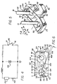
- Fig. 1 illustrates a connector assembly 10 which includes a receptacle connector 12 having a pair of terminals 14, 16, which mates with a plug connector, or connector device 18 that has a pair of corresponding terminal devices 20, 22.
- the particular connector includes a metal plate 24 that holds an initiator 26 that is used to inflate an air bag in an automobile.
- the connector device 18 connects to circuitry that fires the initiator, such as a sensor that senses a collision.
- Fig. 3 shows the plug and receptacle connectors 12, 18 after they have partially mated.
- the terminals 14, 16 have mounted ends fixed in an insulative housing or base 28 of the connector.
- the terminals have free ends 30, 32 whose outer tips touch the terminal devices 20, 22 of the connector device at the beginning of mating as shown in Fig. 3.
- a snap ring 34 on the connector device will snap into a groove 36 of the receptacle connector.
- the lower end 40 of an insulative housing 42 of the connector device will then move down to the position 40A.
- the insulative housing will depress a contacting end portion 44 of a spring device 46. Such depression of the contacting end portion in an inward direction I will move the spring device out of engagement with the second terminal 16.
- the spring device 46 has an anchor end 50 which is anchored in place and connected to the first terminal 14.
- the contacting end portion 44 pivots largely about a pivot axis 52 so the end portion can move in a shorting direction S and an opposite unshorting direction U.
- the contacting end portion 44 pivots in the shorting direction S until a contact location 54 on the contacting end portion engages, or contacts, the outer end portion 32 of the second terminal 16.
- the spring device 46 is formed of sheet metal, and the contacting end portion 44 forms a large aperture 56, with the second terminal 16 projecting through the aperture.
- the aperture results In the contacting end portion having a pair of opposite arms 60, 62 that extend largely in longitudinal directions A, B along which the terminals 14, 16 are spaced.
- the arms are laterally spaced in lateral directions C, D, with arm ends opposite the anchor end being connected together by a laterally extending leg 64.
- the contact location 54 which engages the second terminal, lies on the leg 64.
- Fig. 8 shows the plug connector device 18 as it begins to mate with the receptacle connector 12.
- the connector device will move in the inward direction I by a distance E before it becomes fully mated.
- an inwardly-facing wall 70 on the connector device will engage the leg 64 of the spring device and push it inwardly.
- the leg 64 of the contacting end portion will pivot in the unshorting direction U until it reaches the fully unshorted position shown at 64A where it lies adjacent to the outer surface 66 of the base 28.
- the contact location 54 not only moves inwardly, but also sidewardly in the lateral direction B so it moves away from the axis 72 and cylindrical outer surface of the second terminal 16, by a distance F.
- the spring bias of the spring device causes the contacting end portion 44 and leg 64 to pivot in the shorting direction S, wherein the contact location 54 not only moves outwardly in direction O, but also longitudinally in the direction A until it engages the second terminal.
- the plug housing 42 of the connector device has a recess or keyway 80 which receives an outer part or key 82 of the insulative base 28.
- the anchor end or end portion 50 of the spring device 46 has a hole 90 that closely receives the first terminal 14.
- the walls of the hole 90 make an electrical connection between the first terminal and the spring device, and also help position the spring device.
- the spring device it is still possible for the spring device to pivot about the axis 73 of the first terminal.
- a touching which results In shorting the two terminals, could be disastrous, In that such shorting would probably not be apparent until it caused failure of the air bag to deploy in a collision.
- Applicant takes several steps to prevent such accidental touching, which may be used in combination or independently.
- an isolator 92 shown in Fig. 8, which surrounds an inner part 94 of the second terminal free end portion 32.
- Applicant considers the terminal free end portion 32 to be the part that extends outwardly from a location 96 where the contacting end portion at leg 64A lies in its fully unshorted position.
- Each terminal also has an anchored part 98 lying in the base.
- the base 28 is wide inward of the location 96, so the contact end portion cannot pivot any further In the unshorting direction inward of the location 96.
- the isolator 92 which is formed of dielectric material, provides a barrier against contact of terminal 16 with either of the arms 60, 62, if the spring device should pivot about the axis 73.
- the isolator 92 is preferably molded as part of the base 28, although it can be a separate element.
- the isolator 92 has a small radial thickness T, to avoid interfering with pivoting of the contact end portion in the unshorting direction.
- the thickness T is preferably less than the width W of the terminal free outer end portion, and is desirably less than one-half W. Applicant prefers to taper the isolator so it is of progressively greater thickness at more inward locations.
- the spring device pivots about axis 73 to a position where there Is interference with the isolator, then as the contacting end portion pivots in the unshorting direction, the isolator will tend to realign the spring device.
- the isolator will realign the spring device so it is closer to the desired position wherein the Inner surfaces of the arms which form the walls of the aperture 60, are equally spaced from the second terminal.
- Another way in which applicant avoids unwanted pivoting of the spring device about axis 73 is to provide a tab 100 which is bent to extend inwardly, and which is closely received in a slot 102 formed in the base 28.
- the tab limits pivoting of the spring device about the first terminal axis 73.
- the tab therefore further prevents the spring device from engaging the second terminal when the two connectors are fully mated.
- Applicant prefers to form a pair of barbs 104 on the tab, which are bent slightly out of the plane of the rest of the tab. The barbs dig into the plastic base 28 and better anchor the spring device so it lies dose to the base. It is noted that the tab is spaced only a moderate distance from the first terminal axis 73, so it is still possible for the spring device to pivot about the first terminal axis 73.
- Applicant further assures that the spring device will lie dose to its desired position, shown in solid lines in Fig. 6. If the spring device pivots by an angle G of more than 10° and preferably if it pivots by only about 5°, to the position 46B, a side edge 106 of the spring device will overhang a side location 110 of the key formed by the base 28. In that event, when the connector device is mated with the connector, the inclined side walls of the recess or keyway 80 (Fig. 8) of the connector device housing will tend to press the side edge 106 of the spring device back towards the desired position shown in solid lines in Fig. 6.
- leg 64 The provision of two arms 60, 62 to support the leg 64, provides some leg stability. However there is still a possibility that the leg 64 will bend and bring the legs 60, 62 closer together and thereby increase the possibility that one of them will inadvertently touch the second terminal. To avoid this, applicant provides a depression or deformation 112 in the leg 64, with the leg portion in the depression 112 being deformed out of the plane of the rest of the leg 64.
- the depression which is shown in the middle of the leg but which can lie along an edge, greatly strengthens the leg against bending about an imaginary axis extending in the longitudinal directions A, B.
- the spring device 46 may be very small.
- a spring device constructed by applicant for an automotive air bag initiator has an overall length L of only 6.35 mm (one-quarter Inch), so several features of the spring device are of almost microscopic dimensions. The provision of several means to keep the spring device in its preferred alignment position, reduces the possibility of a catastrophic shorting (which would prevent an air bag from deploying in a collision).
- each terminal such as the first one 14 is preferably formed with an interior 120 of brass and with a gold plating 122 around the brass to avoid corrosion and assure good electrical connections.
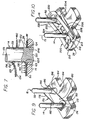
- Applicant constructs the anchor end 50 of the spring device so it has two abutments 123, 124 that can abut largely opposite sides of the first terminal, to securely hold the anchor end to the first terminal and assure a good electrical connection therewith.
- the hole 90 in the anchor end Includes two slots 126, 128 that results in the two abutments 123, 124.
- each abutment has an end 123E, 124E with a rounded Inner comer 130, 132 adjacent to the inner face 134 of the spring device, and the first abutment has a sharp comer 136 at its outer face.
- the rounded corners 130, 132 are provided to prevent the spring device from scratching off the softer gold on the terminal 14 as the spring device is installed.
- the spring device at 46C shows it, during installation, while the spring device at 46 shows it fully installed.
- the first abutment 123 is in the form of a finger that extends at an outward incline at locations progressively closer to the first terminal axis 73.
- Fig. 4 is a schematic diagram of one example of an initiator circuit, where a resistor 150 represents the resistance of the initiator charge, and a voltage source 152 tends to apply current through the initiator to fire it.
- a collision sensor 154 comprises a switch which closes in the event of sudden deceleration, to allow current from the voltage source 152 to pass through the initiator 150 and fire it. When the spring device 46 shorts the terminals 14, 16, sufficient current cannot flow from the voltage source to fire the initiator charge.
- the spring device 46 was constructed of beryllium copper sheet metal having a thickness of 0.10 mm (4 mils; one mill equals one thousandth inch).
- the spring device had an overall length L (Fig. 6) of 6.15 mm (0.242 inch) and width M of 3.05 mm (0.120 inch). The other dimensions are relative to those stated, as shown in Figs. 6 and 8.
- Each of the terminals around which the spring device was mounted, had an outside diameter of 1.00 mm (0.040 inch).
- Fig. 9 shows a spring device 170 formed of a length of spring wire, instead of being formed of sheet metal.
- a spring wire has opposite ends 172, 174, and has at least one turn of a coil at each end, and preferably a plurality of turns.
- the spring device also has a contacting end portion 176 forming a large aperture 180 and forming a pair of arms 182, 184 with their ends connected by a transverse leg 186.
- the leg has a curved center 190 that closely surrounds the second terminal 16 when the spring device is in its shorting position.
- One of the coiled ends 174 lies in a hole 192 formed in the base 194 of the connector.
- An insulative isolator 196 surrounds an inner part of the second terminal free end portion 32.
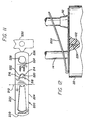
- Figs. 10 - 12 show a spring device 200 which is largely similar to that of Figs. 1 - 8, but which results in longer spring arms 202, 204 for more resilience.
- the base 28 is of the same construction.
- the device includes outer and Inner parts 206, 208 connected at a substantially 180° fold at 210.
- An anchor end 212 is formed in the lower part, and Includes an anchor hole 214 with slots 216, 218 that result in two abutments 220, 222 that engage the terminal 14.
- the lower part Includes a tab 224 which is received in a slot 102 of the base.
- the lower part also includes an extension 226 with an opening 228 (which could be a slot) that receives the isolator 92.
- walls of the opening lie on opposite sides of the Isolator and further stabilize the rotational position of the device about the axis 73 of the first terminal 14.
- the bendable arms 202, 204 extend along substantially the entire length of the upper part, with the arm ends connected by a leg 230.
- Fig. 11 shows the device after it has been blanked from a large sheet of metal, but before the bending operations.
- the carrier which connects numerous spring devices is indicated at 232.
- the invention provides a connector system and a shorting spring device for shorting a pair of terminals of a connector when that connector is not mated to another one.
- the spring device includes an anchor end which is anchored in place and a contacting end portion which can pivot in shorting and unshorting directions wherein it moves outwardly and against a second terminal, and inwardly and away from the second terminal.
- An isolator of dielectric material can surround an inner portion of the second terminal outer end portion. The Isolator prevents the contact end portion of the spring device from shifting sidewardly and touching the second terminal when the contacting end portion has been pivoted to its unshorting position.
- the contacting end portion which is the portion that pivots In the shorting and unshorting directions, can include a large aperture through which the second terminal projects.
- the aperture forms a pair of parallel arms extending largely in a longitudinal direction and having ends joined by a laterally extending leg. The two arms stabilize the position of the leg which forms a contact location that engages the second terminal.
- the spring device can be formed of sheet metal with a hole that closely receives the first terminal and with a tab extending inwardly into the insulative base to limit pivoting of the spring device about the first terminal.
- the anchor end portion can have slots extending from the hole that closely surrounds the first terminal, to form at least two abutments spaced about the hole.
- Both abutments preferably have rounded Inner corners to avoid scratching the first terminal during installation, and with one of the abutments preferably having a sharp outer corner which digs into the first terminal.
- the spring device can be formed of a length of spring wire, preferably with coiled ends tightly engaging the first terminal.
- the connectors can have other terminals, although those used for automotive air bag systems generally have only two terminals.
Landscapes
- Engineering & Computer Science (AREA)
- Mechanical Engineering (AREA)
- Details Of Connecting Devices For Male And Female Coupling (AREA)
- Air Bags (AREA)
Description
- An automobile air bag can be deployed by an initiator that is constantly connected to a voltage source, but with the initiator terminals constantly shorted by a sensor. When the sensor detects a collision, its shorting switch opens and allows current to pass through the initiator to deploy the air bag. During vehicle maintenance, a repairman may wish to disconnect the collision sensor from the initiator. In the past, disconnection would lead to firing of the initiator and deployment of the air bag. Accordingly, many prior air bag systems have been constructed to prevent repairmen from disconnecting the connector from the initiator, which hampers repairmen.
- The connector can be made disconnectable from the initiator, by providing a shorting device that automatically shorts the terminals of the initiator when the connector is disconnected from the initiator. Such automatic shorting devices are known, with U.S. Patent 4,971,568 by Cronin showing one example, wherein a leaf spring pivots up and against a terminal to ground it, until a mating connector pushes down the leaf spring.
US Patent 4,628,818 showing another example, having a leaf spring with a bent back leaf spring portion which pivots downwardly to interrupt the contact between the terminals when mated with the corresponding connector. - However, in a critical application such as an air bag system, any shorting device must have great reliability, especially in assuring that it does not inadvertently short the terminals when the sensor connector has been connected to the initiator. Such inadvertent shorting would result in the air bag not deploying in the event of a crash. A shorting device which was of high reliability, especially in assuring that a pair of terminals are not shorted when two connectors mate, would be of considerable value.
- In accordance with one embodiment of the present invention, a connector system and connector is provided which includes a shorting spring device that shorts a pair of connector terminals, and that is reliably moved to a position where it does not short the terminals when the connector mates with another connector. The spring device has an anchor end permanently connected to the first terminal, and has a contacting end portion which pivots In shorting and unshorting directions against and away from the second terminal.
- In a preferred embodiment of the invention, to prevent accidental shorting when the connectors are mated and the contact end portion has been moved inwardly to Its unshorting position, an isolator of dielectric material is provided that surrounds an Inner portion of the second terminal, with the contacting end portion lying around the isolator.
- The spring device can be formed of a piece of sheet metal with its anchor end having a hole receiving the first terminal, and with the sheet metal forming a tab extending inwardly Into a slot in the base. The tab in connection with the slot limits a possible rotation of the spring device about the first terminal and therefore supports the prevention against accidental shorting when the connectors are mated.
- The contacting end portion of the spring device can include a large aperture through which the second terminal projects. The aperture results in the contact end portion having a pair of arms on laterally opposite sides of the second terminal. The arms are connected by a laterally extending leg that forms a contact location that will engage the second terminal.
- The anchor end of the spring device can be rigidly fixed to the first terminal by forming slots that leave a pair of abutments, and with one of the abutments initially extending at an incline but being pressed down to penetrate into the surface of the first terminal.
- The novel and inventive features of the invention are set forth with particularity in the appended claims, which will be explained and supported in more detail and best understood from the following description when read in conjunction with the accompanying drawings:
- Fig. 1
- is an isometric view of a connector and connector device of the present invention.
- Fig. 2
- is a plan view of the connector of Fig. 1, but without the spring device in place.
- Fig. 3
- is a sectional view of the connector system of Fig. 1, with the connector and connector device in a partially mated configuration.
- Fig. 4
- is a schematic view of the circuitry of an air bag system which includes the connector assembly of Fig. 1.
- Fig. 5
- is an isometric view of a portion of the connector of Fig. 3.
- Fig. 6
- is a plan view of the spring device of the connector Fig. 5, shown prior to bending of the tab thereof, and showing, in phantom lines, the position of the base.
- Fig. 7
- is an enlarged sectional view of the first terminal of the connector of Fig. 5, showing the manner in which the anchor end of the spring device is installed.
- Fig. 8
- is an enlarged view of a portion of Fig. 3.
- Fig. 9
- is an isometric view of a connector constructed in accordance with another embodiment of the invention.
- Fig. 1 illustrates a connector assembly 10 which includes a
receptacle connector 12 having a pair ofterminals connector device 18 that has a pair of correspondingterminal devices metal plate 24 that holds aninitiator 26 that is used to inflate an air bag in an automobile. Theconnector device 18 connects to circuitry that fires the initiator, such as a sensor that senses a collision. - Fig. 3 shows the plug and
receptacle connectors terminals base 28 of the connector. The terminals havefree ends terminal devices connector 18 is pushed down, asnap ring 34 on the connector device will snap into a groove 36 of the receptacle connector. Thelower end 40 of aninsulative housing 42 of the connector device will then move down to theposition 40A. In moving down, the insulative housing will depress a contactingend portion 44 of aspring device 46. Such depression of the contacting end portion in an inward direction I will move the spring device out of engagement with thesecond terminal 16. - As shown in Fig. 5, the
spring device 46 has ananchor end 50 which is anchored in place and connected to thefirst terminal 14. The contactingend portion 44 pivots largely about apivot axis 52 so the end portion can move in a shorting direction S and an opposite unshorting direction U. When the contactingend portion 44 is not pushed inwardly in direction I, it pivots in the shorting direction S until acontact location 54 on the contacting end portion engages, or contacts, theouter end portion 32 of thesecond terminal 16. Thespring device 46 is formed of sheet metal, and the contactingend portion 44 forms alarge aperture 56, with thesecond terminal 16 projecting through the aperture. The aperture results In the contacting end portion having a pair ofopposite arms terminals leg 64. Thecontact location 54 which engages the second terminal, lies on theleg 64. - Fig. 8 shows the
plug connector device 18 as it begins to mate with thereceptacle connector 12. The connector device will move in the inward direction I by a distance E before it becomes fully mated. During such inward movement, an inwardly-facingwall 70 on the connector device will engage theleg 64 of the spring device and push it inwardly. Theleg 64 of the contacting end portion will pivot in the unshorting direction U until it reaches the fully unshorted position shown at 64A where it lies adjacent to theouter surface 66 of thebase 28. During such unshorting movement, thecontact location 54 not only moves inwardly, but also sidewardly in the lateral direction B so it moves away from the axis 72 and cylindrical outer surface of thesecond terminal 16, by a distance F. Conversely, when the connector device unmates, the spring bias of the spring device causes the contactingend portion 44 andleg 64 to pivot in the shorting direction S, wherein thecontact location 54 not only moves outwardly in direction O, but also longitudinally in the direction A until it engages the second terminal. It is noted that theplug housing 42 of the connector device has a recess orkeyway 80 which receives an outer part orkey 82 of theinsulative base 28. - As shown in Fig. 6, the anchor end or
end portion 50 of thespring device 46 has ahole 90 that closely receives thefirst terminal 14. The walls of thehole 90 make an electrical connection between the first terminal and the spring device, and also help position the spring device. However, it is still possible for the spring device to pivot about theaxis 73 of the first terminal. Unless precautions were taken, it might be possible for the spring device to pivot far enough that one of thearms second terminal 16, even when the contacting end portion had been pivoted to its fully unshorted position. As discussed above, such a touching, which results In shorting the two terminals, could be disastrous, In that such shorting would probably not be apparent until it caused failure of the air bag to deploy in a collision. Applicant takes several steps to prevent such accidental touching, which may be used in combination or independently. - In accordance with the present invention, applicant provides an isolator 92, shown in Fig. 8, which surrounds an
inner part 94 of the second terminalfree end portion 32. Applicant considers the terminalfree end portion 32 to be the part that extends outwardly from alocation 96 where the contacting end portion atleg 64A lies in its fully unshorted position. Each terminal also has an anchoredpart 98 lying in the base. Thebase 28 is wide inward of thelocation 96, so the contact end portion cannot pivot any further In the unshorting direction inward of thelocation 96. Theisolator 92, which is formed of dielectric material, provides a barrier against contact ofterminal 16 with either of thearms axis 73. Theisolator 92 is preferably molded as part of thebase 28, although it can be a separate element. - The
isolator 92 has a small radial thickness T, to avoid interfering with pivoting of the contact end portion in the unshorting direction. The thickness T is preferably less than the width W of the terminal free outer end portion, and is desirably less than one-half W. Applicant prefers to taper the isolator so it is of progressively greater thickness at more inward locations. As a result, if the spring device pivots aboutaxis 73 to a position where there Is interference with the isolator, then as the contacting end portion pivots in the unshorting direction, the isolator will tend to realign the spring device. The isolator will realign the spring device so it is closer to the desired position wherein the Inner surfaces of the arms which form the walls of theaperture 60, are equally spaced from the second terminal. - Another way in which applicant avoids unwanted pivoting of the spring device about
axis 73, is to provide atab 100 which is bent to extend inwardly, and which is closely received in aslot 102 formed in thebase 28. The tab limits pivoting of the spring device about the firstterminal axis 73. The tab therefore further prevents the spring device from engaging the second terminal when the two connectors are fully mated. Applicant prefers to form a pair ofbarbs 104 on the tab, which are bent slightly out of the plane of the rest of the tab. The barbs dig into theplastic base 28 and better anchor the spring device so it lies dose to the base. It is noted that the tab is spaced only a moderate distance from the firstterminal axis 73, so it is still possible for the spring device to pivot about the firstterminal axis 73. - Applicant further assures that the spring device will lie dose to its desired position, shown in solid lines in Fig. 6. If the spring device pivots by an angle G of more than 10° and preferably if it pivots by only about 5°, to the
position 46B, aside edge 106 of the spring device will overhang a side location 110 of the key formed by thebase 28. In that event, when the connector device is mated with the connector, the inclined side walls of the recess or keyway 80 (Fig. 8) of the connector device housing will tend to press theside edge 106 of the spring device back towards the desired position shown in solid lines in Fig. 6. - The provision of two
arms leg 64, provides some leg stability. However there is still a possibility that theleg 64 will bend and bring thelegs deformation 112 in theleg 64, with the leg portion in thedepression 112 being deformed out of the plane of the rest of theleg 64. The depression, which is shown in the middle of the leg but which can lie along an edge, greatly strengthens the leg against bending about an imaginary axis extending in the longitudinal directions A, B. - Thus, applicant provides several ways to avoid unwanted shorting of the terminals when the connectors are fully mated. It should be noted that the
spring device 46 may be very small. A spring device constructed by applicant for an automotive air bag initiator, has an overall length L of only 6.35 mm (one-quarter Inch), so several features of the spring device are of almost microscopic dimensions. The provision of several means to keep the spring device in its preferred alignment position, reduces the possibility of a catastrophic shorting (which would prevent an air bag from deploying in a collision). - As shown in Fig. 7, each terminal such as the
first one 14 is preferably formed with an interior 120 of brass and with agold plating 122 around the brass to avoid corrosion and assure good electrical connections. Applicant constructs theanchor end 50 of the spring device so it has twoabutments hole 90 in the anchor end Includes twoslots abutments - Referring again to Fig. 7, it can be seen that each abutment has an
end 123E, 124E with a roundedInner comer inner face 134 of the spring device, and the first abutment has asharp comer 136 at its outer face. Therounded corners first abutment 123 is in the form of a finger that extends at an outward incline at locations progressively closer to the firstterminal axis 73. When the spring device has been pushed down, applicant installs a tool around thefirst terminal 14 and presses down on the tool to firmly depress thefinger region 140. This causes thesharp corner 136 to "dig in" or penetrate into the first terminal, through the gold layer. This is because the distance between theadjacent corners first abutment 123 is bent down to lie on the same plane as the second one. The penetration serves to firmly anchor the spring device to the first terminal, to assure reliable electrical connection therewith, as well as to resist turning of the spring device about the first terminal. - Fig. 4 is a schematic diagram of one example of an initiator circuit, where a
resistor 150 represents the resistance of the initiator charge, and avoltage source 152 tends to apply current through the initiator to fire it. Acollision sensor 154 comprises a switch which closes in the event of sudden deceleration, to allow current from thevoltage source 152 to pass through theinitiator 150 and fire it. When thespring device 46 shorts theterminals - Applicant has designed a spring device and connector system of the construction shown in Figs. 1 - 8. The
spring device 46 was constructed of beryllium copper sheet metal having a thickness of 0.10 mm (4 mils; one mill equals one thousandth inch). The spring device had an overall length L (Fig. 6) of 6.15 mm (0.242 inch) and width M of 3.05 mm (0.120 inch). The other dimensions are relative to those stated, as shown in Figs. 6 and 8. Each of the terminals around which the spring device was mounted, had an outside diameter of 1.00 mm (0.040 inch). - Fig. 9 shows a
spring device 170 formed of a length of spring wire, instead of being formed of sheet metal. A spring wire has opposite ends 172, 174, and has at least one turn of a coil at each end, and preferably a plurality of turns. The spring device also has a contactingend portion 176 forming alarge aperture 180 and forming a pair ofarms transverse leg 186. The leg has acurved center 190 that closely surrounds thesecond terminal 16 when the spring device is in its shorting position. One of the coiled ends 174 lies in ahole 192 formed in thebase 194 of the connector. Aninsulative isolator 196 surrounds an inner part of the second terminalfree end portion 32. - Figs. 10 - 12 show a
spring device 200 which is largely similar to that of Figs. 1 - 8, but which results inlonger spring arms base 28 is of the same construction. The device includes outer andInner parts anchor end 212 is formed in the lower part, and Includes ananchor hole 214 withslots 216, 218 that result in twoabutments tab 224 which is received in aslot 102 of the base. The lower part also includes anextension 226 with an opening 228 (which could be a slot) that receives theisolator 92. As a result, walls of the opening lie on opposite sides of the Isolator and further stabilize the rotational position of the device about theaxis 73 of thefirst terminal 14. - The
bendable arms leg 230. Fig. 11 shows the device after it has been blanked from a large sheet of metal, but before the bending operations. The carrier which connects numerous spring devices is indicated at 232. - Thus, the invention provides a connector system and a shorting spring device for shorting a pair of terminals of a connector when that connector is not mated to another one. The spring device includes an anchor end which is anchored in place and a contacting end portion which can pivot in shorting and unshorting directions wherein it moves outwardly and against a second terminal, and inwardly and away from the second terminal. An isolator of dielectric material can surround an inner portion of the second terminal outer end portion. The Isolator prevents the contact end portion of the spring device from shifting sidewardly and touching the second terminal when the contacting end portion has been pivoted to its unshorting position. The contacting end portion, which is the portion that pivots In the shorting and unshorting directions, can include a large aperture through which the second terminal projects. The aperture forms a pair of parallel arms extending largely in a longitudinal direction and having ends joined by a laterally extending leg. The two arms stabilize the position of the leg which forms a contact location that engages the second terminal. The spring device can be formed of sheet metal with a hole that closely receives the first terminal and with a tab extending inwardly into the insulative base to limit pivoting of the spring device about the first terminal. The anchor end portion can have slots extending from the hole that closely surrounds the first terminal, to form at least two abutments spaced about the hole. Both abutments preferably have rounded Inner corners to avoid scratching the first terminal during installation, and with one of the abutments preferably having a sharp outer corner which digs into the first terminal. The spring device can be formed of a length of spring wire, preferably with coiled ends tightly engaging the first terminal. Of course, the connectors can have other terminals, although those used for automotive air bag systems generally have only two terminals.
- Although particular embodiments of the invention have been described and illustrated herein, it is recognized that modifications and variations may readily occur to those skilled in the art, and consequently, it is intended that the claims be interpreted to cover such modifications and equivalents.
Claims (21)
- A connector system that includes a connector (12) and a connector device (18) that can mate, said connector device (18) having an insulative housing (42) and a pair of terminal devices (20, 22), and said connector (12) having an insulative base (28, 194) and first and second terminals (14, 16) that have anchored parts anchored to said base (28, 194) and free end portions (30, 32) that extend outwardly from said base (28, 194), wherein said connector (12) includes an electrically conductive spring device (46, 170, 200) having an anchor end portion (50, 212) connected to said first terminal (14) and having a contacting end portion (44, 176, 230) which can pivot in opposite shorting and unshorting directions (S, U), wherein when said contacting end portion (44, 176, 230) pivots in said shorting direction (S) it moves both outwardly (O) and toward (A) said second terminal (16) until a contact location (54) on said contacting end portion (44, 176, 230) engages said second terminal (16), and wherein said housing (42) pushes inwardly (I) against said contacting end portion (44,176, 230) when said connector (12) and connector device (18) mate, to force said contacting end portion (44, 176, 230) to pivot in said unshorting direction (U) wherein said contact location (54) moves both inwardly (I) and away (B) from said second terminal (16), characterized by:an isolator (92, 196) of insulative material which at least partially surrounds an inner part (94) of said second terminal free end portion (32) to prevent said contacting end portion (44, 176, 230) of said spring device (46, 170, 200) from touching said second terminal (16) when said connector (12) and connector device (18) are fully mated and said contacting end portion (44, 176, 230) has been fully pivoted in said unshorting direction (U).
- Connector system as described in claim 1 wherein:said isolator (92, 196) has an inner location (96) that lies beside said contact location (54) when said contacting end portion (44, 176, 230) has been fully pivoted in said unshorting direction (U), said isolator inner location (96) having a thickness (T) less than the width (W) of said second terminal (16) at said inner location (96).
- Connector system as claimed in at least one of claims 1 or 2 wherein:said isolator (92, 196) is tapered in width, with said isolator (92, 196) having an outer end of least width.
- Connector system as claimed in at least one of claims 1 to 3 wherein:said spring device (46, 200) comprises a piece of sheet metal, with said anchor end portion (50, 212) having a hole (90, 214) which closely receives said first terminal (14); said base (28) has a slot (102), and said spring device (46, 200) has a tab (100, 224) which projects inwardly into said slot (102), to limit pivoting of said spring device (46, 200) about said first terminal (14).
- Connector system as claimed in at least one of claims 1 to 4 wherein:said spring device (46,200) is formed of sheet metal, and said contacting end portion (44, 230) has an aperture and forms opposite arms (60, 62; 202, 204) that lie on laterally opposite sides of said second terminal (16) and also forms a largely laterally extending leg (64, 230) that connects said arms (60, 62; 202, 204) and that lies on a side of said second terminal (16) that is opposite to said first terminal (14); said leg (64, 230 ) having an elongated depression (112) extending in a direction along the length of said leg, to resist bowing of the contact end portion.
- Connector system as claimed in at least one of claims 1 to 5 wherein:said spring device (46, 200) comprises a piece of sheet metal, and said anchor end portion (50, 212) has a hole (90, 214) which closely receives said first terminal (14); said anchor end portion (50, 212) having a plurality of slots (126, 128; 216, 218) extending from said hole (90, 214) and forming a plurality of separate terminal abutments (123, 124; 220, 222) spaced about said hole (90, 214) each having inner and outer faces (134) and each having an end (123E, 124E) that engages said first terminal (14), with said end of each abutment forming a rounded comer portion (130,132) at said inner face(134), and with at least one of said abutments (123, 124; 220, 222) having a sharp comer (136) at said outer face which penetrates into said first terminal (14).
- Connector system as claimed in at least one of claims 1 to 6 wherein:said spring device (46) includes outer and inner parts (206, 208) connected at a substantially 180° fold which lies on a side of said first terminal (14) which is opposite said second terminal (16), said inner part (208) forming said anchor end portion (212) and said outer part forming said contacting end portion (44) and being free of restraint except of said fold to thereby provide a long beam.
- The connector system described in claim 7 wherein:said inner part (208) includes an opening forming opening walls that lie on opposite sides of said isolator (92).
- Connector system as claimed in at least one of claims 1 to 3 wherein:said spring device (46) comprises a length of spring wire, with a portion of said wire forming said contacting end portion (176) extending in a loop around said second terminal (16), with said wire portion biased in said shorting direction (S) but being pivotal in said unshorting direction (U) to a position substantially against said base (28).
- Connector system as claimed in at least one of claims 1 to 3 wherein:said spring device (46) comprises a length of spring wire which has at least one turn that forms said anchor end portion and that is tightly wound about said first terminal (14) to anchor said wire to said first terminal (14), said wire extending in a loop about second terminal (16), with said loop being pivotable to pivot in said shorting and un shorting directions (S, U).
- Connector system as claimed in at least one of claims 1 to 10 wherein:said base (28) of said connector (12) has an outer surface portion (42) forming a key with opposite side locations on opposite sides of said second terminal (16), and said housing (42) of said connector device (18) having a recess forming a keyway (80) that closely receives said key as said connector (12) and connector device (18) mate; said contact end portion (44,176) of said spring device (46, 170, 200) has opposite edges that lie near enough to said opposite side locations of said key, that each of said spring device edges will overhang a corresponding one of said key side locations if said spring device (46, 170, 200) is turned more than 10° from a desired position wherein said spring device edges (106) are equally spaced from said key opposite side locations.
- A connector (12) which has an insulative base (28) and first and second terminals (14, 16) that project outwardly from a surface of said base (28) and which are constructed to mate with terminal devices (20, 22) of a mating connector device (18) which has a housing (42) that will closely approach said base surface when said connectors (12, 18) mate, wherein said terminals (14,16) must be continually shorted except when said connector (12) is mated to said connector device (18), comprising:a spring device (46) which is formed of sheet metal and which has an anchor end (50) with a hole (90) that closely receives said first terminal (14),said spring device (46) having a contacting end portion (44) which can move partially in said outward direction (O) and against said second terminal (16), but which is pressed by said housing (42) of said connector device (18) in an inward direction (I) and out of contact with said second terminal (16) when said connector device(18) mates with said connector (12);an isolator (92) of dielectric material lying about a portion of said second terminal (16), which said contacting end portion (44) substantially lies about when said contacting end portion (44) is in its innermost position (64A) when said connector (12) and connector device (18) are mated, said isolator (92) having an outer end lying rearward of the location where said contacting outer end moves against said second terminal (16).said base (28) has a slot (102), and said spring device (46) has a tab (100) that extends inwardly into said slot (102).
- A connector (12) which has an insulative base (28) and first and second terminals (14, 16) that are longitudinally spaced apart and that project outwardly from a surface of said base (28) and which are constructed to mate with terminal devices (20, 22) of a mating connector device (18) which has a housing (42) that will closely approach said base (28) when said connectors (12, 18) mate, wherein said longitudinal and outward directions are normal to each other and to a lateral direction, wherein said terminals (14, 16) must be continually shorted except when said connector (12) is mated to said connector device (18), comprising:a spring device (46) which is formed of sheet metal, said spring device (46) having an anchor end (50) with a hole (90) that closely receives and is anchored to said first terminal (14), said spring device (46) also having a contacting end portion (44) which has an aperture through which said second terminal (16) extends and which forms a pair of opposite arms (60, 62) that extend largely in said longitudinal direction and which lie on laterally opposite sides of said second terminal (16), said contacting end portion (44) having a laterally extending leg (64) that connects said arms (60, 62), with each arm extending from near said anchor end (50) to said leg (64), said contacting end portion (44) being biased to pivot in a shorting direction (S) so said leg (64) moves outwardly (O) and against second terminal (A), with said pair of arms (60, 62) stabilizing the orientation of said leg (64), but said contacting end portion (44) being pivotable in an opposite unshorting direction (U), andan isolator (92) of dielectric material surrounding a portion of said second terminal (16) that lies beside said leg (64) of said contact end portion (44) when said contact end portion (44) is pivoted in said unshorting direction (U) to an unshorting position (64A), said isolator (92) having an outer end that lies inward of where said leg moves against terminal (16) when said contact end portion (44) pivots in said shorting direction (S).
- Connector as claimed in claims 13 wherein:said leg (64) has an elongated portion (112) extending parallel to said leg (64) and deformed out of the plane of the sheet metal of said leg (64), to avoid warping of said contact end portion (44).
- Connector as claimed in claim 13 or 14 wherein:said base (28) has a slot (102) extending inwardly therein, and said spring device (46) has a tab (100) which is received in said slot (102).
- Connector as claimed in at least one of claims 13 to 15 comprising:a spring device (46) which includes inner and outer parts (206, 208) connected by a fold, said inner part (208) being anchored to said first terminal (14) and said fold lying on a side of said first terminal (14) which is opposite said second terminal (16), said outer part (206) being free of restraint except at said fold and being biased to move largely outwardly but being positioned to be deflected inwardly by said second connector device (18) during mating, with said outer part (206) having a contact location (54) lying on a side of said second terminal (16) opposite said first terminal (14), said contact location (54) moving outwardly (O) and toward (A) said second terminal (16) and eventually against said second terminal (16), as said outer part (206) moves outwardly (O).
- A connector (12) comprising:an insulative base (28);a plurality of terminals (14, 16) mounted in said base (28) and having free end portions (30, 32) extending in an outward direction from said base (28);a spring device (46) which is formed of sheet metal and which has an anchor end portion (50) having a hole (90) anchored to a first of said terminals and a contact end portion (44) which can engage a second of said terminals;said spring can pivot in opposite shorting and unshorting directions (S, U);an isolator (92, 196) of insulative material which at least partially surrounds an inner part (94) of said second terminal free end portion (32) no prevent said contacting end portion (44) of said spring device (46) from touching said second terminal (16) when said connector (12) and connector device (18) are fully mated and said contacting end portion (44, 176, 230) has- been fully pivoted in said unshorting direction (U).said anchor end portion (50) having a plurality of slots (126, 128) extending from said hole (90) and forming a plurality of separate terminal abutments spaced about said hole (90) each having inner and outer faces (134) and each having an end (123E, 124E) that engages said first terminal (14), with said end of each abutment (123,124) forming a rounded comer portion (130,132) at said inner face (134).
- Connector described in claim 17 wherein:at least one of said abutments (123, 124) has a terminal engaging end that forms a sharp comer (136) at said outer face and that penetrates into said first terminal.
- Connector as claimed in at least one of claims 17 or 18 wherein:said base (28) has a slot (102), and said spring device (46) has a tab (100) which projects inwardly into said slot (102), and which limits pivoting of said spring device (46) about said first terminal.
- A method for constructing a connector (12) that has an insulative base (28) and a pair of terminals (14, 16) mounted in the base (28) and having free end portions (30, 32) that extend outwardly from the base (28), and that includes a spring device (46) connected to said first terminal (14) and having a contacting end portion (44) that can move outwardly (O) and also in a sideward direction that is perpendicular to said outward direction (O) toward said second terminal (16) to a shorting position (S) to engage a location on said second terminal (16), and wherein said contact end can move inwardly (I) and also sidewardly away (B) from said terminal (16) to an unshorted position (64A), wherein the method safeguards against said contacting end portion (44) touching said second terminal (16) when it has moved to said unshorted position (64A), characterized by:forming said base (28) with an isolator (92, 196) that at least partially surrounds an inner portion (94) of said terminal free end portion (32), but which has a thickness (T) no more than the width (W) of said second terminal (16), to form a barrier that prevents said contacting end portion (44) in said unshorted position (64A) from moving sidewardly but not outwardly (O) and touching said second terminal (16), while avoiding interference with movement of said contact end (44) to said unshorting position (64A).
- The method described in claim 20 including:forming said base (28) with an inwardly extending slot (102);forming said spring device (46) of sheet metal, with walls forming a hole (90) and with a tab (100) that extends at substantially a right angle from an adjacent portion of said sheet metal;moving said spring device (46) so the walls of said hole (90) receive said first terminal (14) to connect to said first terminal (14) and to prevent sideward translation of said spring device (46), and moving said tab (100) inwardly into said slot (102), to limit pivoting of said spring device (46) about said first terminal (14).
Applications Claiming Priority (2)
| Application Number | Priority Date | Filing Date | Title |
|---|---|---|---|
| US08/069,793 US5401180A (en) | 1993-06-01 | 1993-06-01 | Connector shorting spring |
| US69793 | 1993-06-01 |
Publications (3)
| Publication Number | Publication Date |
|---|---|
| EP0632546A2 EP0632546A2 (en) | 1995-01-04 |
| EP0632546A3 EP0632546A3 (en) | 1996-05-01 |
| EP0632546B1 true EP0632546B1 (en) | 2003-03-05 |
Family
ID=22091245
Family Applications (1)
| Application Number | Title | Priority Date | Filing Date |
|---|---|---|---|
| EP94108377A Expired - Lifetime EP0632546B1 (en) | 1993-06-01 | 1994-05-31 | Connector shorting spring |
Country Status (6)
| Country | Link |
|---|---|
| US (1) | US5401180A (en) |
| EP (1) | EP0632546B1 (en) |
| JP (1) | JPH07147173A (en) |
| KR (1) | KR950000474A (en) |
| CA (1) | CA2124663C (en) |
| DE (1) | DE69432204T2 (en) |
Families Citing this family (31)
| Publication number | Priority date | Publication date | Assignee | Title |
|---|---|---|---|---|
| US5648634A (en) | 1993-10-20 | 1997-07-15 | Quantic Industries, Inc. | Electrical initiator |
| US5728964A (en) | 1993-10-20 | 1998-03-17 | Quantic Industries, Inc. | Electrical initiator |
| US5600300A (en) * | 1994-07-15 | 1997-02-04 | Chrysler Corporation | Arrangement for indicating an indicating an interrupted electrical connection |
| GB9423346D0 (en) * | 1994-11-18 | 1995-01-11 | Amp Great Britain | Electrical interconnection system having retention and shorting features |
| EP0734100B1 (en) * | 1995-03-20 | 2003-05-07 | The Whitaker Corporation | Electrical connector with terminal position assurance |
| US5616045A (en) * | 1995-07-14 | 1997-04-01 | Augat Inc. | Squib connector for automotive air bag assembly |
| US5609498A (en) * | 1995-09-19 | 1997-03-11 | Itt Corporation | Secure connector system |
| US5697501A (en) * | 1995-12-21 | 1997-12-16 | Polaroid Corporation | Electrostatic discharge protection device |
| US5895282A (en) * | 1996-05-24 | 1999-04-20 | Thomas & Betts Corporation | Connector for airbag gas generator |
| DE69725423T2 (en) * | 1996-08-12 | 2004-07-22 | Thomas & Betts International Inc., Memphis | DIRECTIONAL IGNITION PILL CONNECTOR FOR MOTOR VEHICLE AIR BAG SYSTEMS |
| EP1378973B1 (en) * | 1996-08-12 | 2007-01-10 | Thomas & Betts International, Inc. | Orientationless squib connector assembly for automotive air bag assemblies |
| US5882224A (en) * | 1996-08-28 | 1999-03-16 | Thomas & Betts International, Inc. | Squib connector socker assembly having shorting clip for automotive air bags |
| US6276953B1 (en) | 1997-12-04 | 2001-08-21 | Thoma & Betts International, Inc. | Orientationless squib connector assembly for automotive air bag assemblies |
| US6261123B1 (en) * | 2000-03-20 | 2001-07-17 | Delphi Technologies, Inc. | Battery pack manual disconnect |
| ATE374709T1 (en) * | 2001-04-03 | 2007-10-15 | Nknm Ltd | UNIT HEAD PIECE/BASE/SHORT CIRCUIT BRIDGE HOLDER FOR A MICRO GAS GENERATOR AND MICRO GAS GENERATOR USING SAME |
| FR2843493B1 (en) * | 2002-08-09 | 2004-12-24 | Amphenol Tuchel Elect | MALE CONNECTOR |
| JP2005353306A (en) * | 2004-06-08 | 2005-12-22 | Sony Corp | AC plug and electric device including the same |
| KR100703624B1 (en) * | 2005-03-04 | 2007-04-05 | 주식회사 대한피엔씨 | Clean shower air shower system |
| TWM277170U (en) * | 2005-05-27 | 2005-10-01 | Joymax Electronics Co Ltd | Signal connector |
| US7354287B1 (en) * | 2006-10-31 | 2008-04-08 | Caterpillar Inc. | Shorting connector |
| US7616421B2 (en) * | 2006-12-18 | 2009-11-10 | Caterpillar Inc. | Electrical interface system |
| US7789685B2 (en) * | 2006-12-18 | 2010-09-07 | Caterpillar Inc | Electrical shorting system |
| US7537473B2 (en) * | 2007-06-28 | 2009-05-26 | Fci Americas Technology, Inc. | Low profile shorting bar for electrical connector |
| GB201204866D0 (en) * | 2012-03-20 | 2012-05-02 | Trw Ltd | Fork type electrical connector |
| USD772231S1 (en) * | 2015-04-16 | 2016-11-22 | Physical Optics Corporation | Universal integrative mission module interface |
| CN106299894A (en) * | 2015-05-22 | 2017-01-04 | 富士康(昆山)电脑接插件有限公司 | Power connector cable-assembly |
| US10662898B2 (en) | 2016-09-08 | 2020-05-26 | Raytheon Company | Integrated thruster |
| US10615547B2 (en) | 2016-09-08 | 2020-04-07 | Raytheon Company | Electrical device with shunt, and receptacle |
| US10046409B2 (en) | 2016-09-08 | 2018-08-14 | Raytheon Company | Methods of making an electrical connection, and of making a receptacle for receiving an electrical device |
| FR3059478A1 (en) * | 2016-11-30 | 2018-06-01 | Tyco Electronics France Sas | ELECTRICAL CONNECTOR FOR A SECURITY RETENTION SYSTEM |
| CN107039864B (en) * | 2017-06-05 | 2023-04-21 | 国网安徽省电力公司六安供电公司 | Adjustable short-circuit piece |
Family Cites Families (7)
| Publication number | Priority date | Publication date | Assignee | Title |
|---|---|---|---|---|
| US3597722A (en) * | 1969-10-13 | 1971-08-03 | Malco Mfg Co Inc | Connector |
| US3668606A (en) * | 1970-10-08 | 1972-06-06 | Malco Mfg Co Inc | Buss connector |
| US3858152A (en) * | 1973-07-13 | 1974-12-31 | Monarch Molding Inc | Intercept connector suitable for use in a telephone system |
| DE2633590C2 (en) * | 1976-07-27 | 1984-09-27 | Daimler-Benz Ag, 7000 Stuttgart | Ignition device for a passive restraint system |
| DE3338929A1 (en) * | 1983-10-27 | 1985-05-09 | Bayern-Chemie Gesellschaft für flugchemische Antriebe mbH, 8261 Aschau | SHORT CIRCUIT SPRING |
| US4971568A (en) * | 1989-12-11 | 1990-11-20 | Polaroid Corporation | Electrical connector with attachment for automatically shorting select conductors upon disconnection of connector |
| FR2689325B1 (en) * | 1992-03-25 | 1996-07-12 | Carrier Kheops Bac | LOCKING DEVICE FOR ELECTRICAL CONNECTORS. |
-
1993
- 1993-06-01 US US08/069,793 patent/US5401180A/en not_active Expired - Lifetime
-
1994
- 1994-04-13 KR KR1019940007709A patent/KR950000474A/en not_active Ceased
- 1994-05-30 CA CA002124663A patent/CA2124663C/en not_active Expired - Fee Related
- 1994-05-31 EP EP94108377A patent/EP0632546B1/en not_active Expired - Lifetime
- 1994-05-31 DE DE69432204T patent/DE69432204T2/en not_active Expired - Fee Related
- 1994-06-01 JP JP6120438A patent/JPH07147173A/en active Pending
Also Published As
| Publication number | Publication date |
|---|---|
| US5401180A (en) | 1995-03-28 |
| JPH07147173A (en) | 1995-06-06 |
| EP0632546A3 (en) | 1996-05-01 |
| DE69432204T2 (en) | 2004-03-18 |
| CA2124663C (en) | 1997-10-21 |
| DE69432204D1 (en) | 2003-04-10 |
| KR950000474A (en) | 1995-01-03 |
| EP0632546A2 (en) | 1995-01-04 |
Similar Documents
| Publication | Publication Date | Title |
|---|---|---|
| US5401180A (en) | Connector shorting spring | |
| US6203342B1 (en) | Grounding plate for orientationless squib connector assembly for automotive air bag assemblies | |
| CA2255239C (en) | Orientationless squib connector assembly for automotive air bag assemblies | |
| EP1009067B1 (en) | Connector structure | |
| KR100530174B1 (en) | Electrical connector assembly comprising locking part | |
| EP1187267B1 (en) | Switch-equipped coaxial connector | |
| US4575172A (en) | Low insertion force electrical connector with stress controlled contacts | |
| US4718854A (en) | Low profile press fit connector | |
| US4988307A (en) | Circuit shorting connector | |
| WO2000074176A1 (en) | Electrical contact receptacle terminal to mate with round and rectangular pins | |
| EP0432368B1 (en) | Electrical connector with attachment for automatically shorting select conductors upon disconnection of connector | |
| US5135417A (en) | Dual usage electrical/electronic pin terminal system | |
| JP3400076B2 (en) | Connector with short-circuit member | |
| US20220368051A1 (en) | Connector device | |
| US12230917B2 (en) | Connector device | |
| EP0840397B1 (en) | Electrical connector assembly with shorting circuit arrangement | |
| JPH10510947A (en) | Connector having spring contact member and short-circuit means | |
| US6039589A (en) | Electrical connector with a shunt incorporated into a secondary locking member | |
| EP0454977B1 (en) | Electrical plug connector with contact strips embedded in an insulator plate for use on circuit board | |
| JP2955008B2 (en) | Short circuit device for electrical connector | |
| EP1069650B1 (en) | Metal terminal | |
| GB2216345A (en) | Pin and socket connector | |
| US5162003A (en) | Electrical connector with a constant radius of curvature beam | |
| EP1041680B1 (en) | Electrostatic discharge protection for a coaxial connector | |
| US20020137395A1 (en) | Socket connector for insertion of audio plug |
Legal Events
| Date | Code | Title | Description |
|---|---|---|---|
| PUAI | Public reference made under article 153(3) epc to a published international application that has entered the european phase |
Free format text: ORIGINAL CODE: 0009012 |
|
| AK | Designated contracting states |
Kind code of ref document: A2 Designated state(s): DE FR GB SE |
|
| PUAL | Search report despatched |
Free format text: ORIGINAL CODE: 0009013 |
|
| AK | Designated contracting states |
Kind code of ref document: A3 Designated state(s): DE FR GB SE |
|
| 17P | Request for examination filed |
Effective date: 19960808 |
|
| RAP1 | Party data changed (applicant data changed or rights of an application transferred) |
Owner name: ITT MANUFACTURING ENTERPRISES, INC. |
|
| 17Q | First examination report despatched |
Effective date: 20000214 |
|
| GRAH | Despatch of communication of intention to grant a patent |
Free format text: ORIGINAL CODE: EPIDOS IGRA |
|
| GRAH | Despatch of communication of intention to grant a patent |
Free format text: ORIGINAL CODE: EPIDOS IGRA |
|
| GRAA | (expected) grant |
Free format text: ORIGINAL CODE: 0009210 |
|
| AK | Designated contracting states |
Designated state(s): DE FR GB SE |
|
| PG25 | Lapsed in a contracting state [announced via postgrant information from national office to epo] |
Ref country code: FR Free format text: LAPSE BECAUSE OF NON-PAYMENT OF DUE FEES Effective date: 20030305 |
|
| REG | Reference to a national code |
Ref country code: GB Ref legal event code: FG4D |
|
| REF | Corresponds to: |
Ref document number: 69432204 Country of ref document: DE Date of ref document: 20030410 Kind code of ref document: P |
|
| PG25 | Lapsed in a contracting state [announced via postgrant information from national office to epo] |
Ref country code: SE Free format text: LAPSE BECAUSE OF FAILURE TO SUBMIT A TRANSLATION OF THE DESCRIPTION OR TO PAY THE FEE WITHIN THE PRESCRIBED TIME-LIMIT Effective date: 20030605 Ref country code: GB Free format text: LAPSE BECAUSE OF NON-PAYMENT OF DUE FEES Effective date: 20030605 |
|
| PLBE | No opposition filed within time limit |
Free format text: ORIGINAL CODE: 0009261 |
|
| STAA | Information on the status of an ep patent application or granted ep patent |
Free format text: STATUS: NO OPPOSITION FILED WITHIN TIME LIMIT |
|
| GBPC | Gb: european patent ceased through non-payment of renewal fee |
Effective date: 20030605 |
|
| EN | Fr: translation not filed | ||
| 26N | No opposition filed |
Effective date: 20031208 |
|
| PGFP | Annual fee paid to national office [announced via postgrant information from national office to epo] |
Ref country code: DE Payment date: 20070702 Year of fee payment: 14 |
|
| PG25 | Lapsed in a contracting state [announced via postgrant information from national office to epo] |
Ref country code: DE Free format text: LAPSE BECAUSE OF NON-PAYMENT OF DUE FEES Effective date: 20081202 |