EP0632442A2 - Disc player and disc loading device - Google Patents
Disc player and disc loading device Download PDFInfo
- Publication number
- EP0632442A2 EP0632442A2 EP94115317A EP94115317A EP0632442A2 EP 0632442 A2 EP0632442 A2 EP 0632442A2 EP 94115317 A EP94115317 A EP 94115317A EP 94115317 A EP94115317 A EP 94115317A EP 0632442 A2 EP0632442 A2 EP 0632442A2
- Authority
- EP
- European Patent Office
- Prior art keywords
- disc
- cartridge
- cartridge holder
- lever
- main body
- Prior art date
- Legal status (The legal status is an assumption and is not a legal conclusion. Google has not performed a legal analysis and makes no representation as to the accuracy of the status listed.)
- Granted
Links
- 238000003780 insertion Methods 0.000 claims description 16
- 230000037431 insertion Effects 0.000 claims description 16
- 230000003287 optical effect Effects 0.000 abstract description 93
- 230000000007 visual effect Effects 0.000 abstract description 2
- 230000006870 function Effects 0.000 description 8
- 230000000717 retained effect Effects 0.000 description 8
- 229920003002 synthetic resin Polymers 0.000 description 5
- 239000000057 synthetic resin Substances 0.000 description 5
- 239000002184 metal Substances 0.000 description 4
- 238000005452 bending Methods 0.000 description 3
- 239000000428 dust Substances 0.000 description 3
- 238000000605 extraction Methods 0.000 description 3
- 230000013011 mating Effects 0.000 description 3
- 239000000853 adhesive Substances 0.000 description 2
- 230000001070 adhesive effect Effects 0.000 description 2
- 230000006835 compression Effects 0.000 description 2
- 238000007906 compression Methods 0.000 description 2
- 230000014759 maintenance of location Effects 0.000 description 2
- 230000005236 sound signal Effects 0.000 description 2
- 238000010276 construction Methods 0.000 description 1
- 230000008021 deposition Effects 0.000 description 1
- 239000011521 glass Substances 0.000 description 1
- 239000004973 liquid crystal related substance Substances 0.000 description 1
- 239000000696 magnetic material Substances 0.000 description 1
- 239000000463 material Substances 0.000 description 1
- 230000005411 photomagnetism Effects 0.000 description 1
- 229920005668 polycarbonate resin Polymers 0.000 description 1
- 239000004431 polycarbonate resin Substances 0.000 description 1
- 238000004080 punching Methods 0.000 description 1
Images


Classifications
-
- G—PHYSICS
- G11—INFORMATION STORAGE
- G11B—INFORMATION STORAGE BASED ON RELATIVE MOVEMENT BETWEEN RECORD CARRIER AND TRANSDUCER
- G11B17/00—Guiding record carriers not specifically of filamentary or web form, or of supports therefor
- G11B17/02—Details
- G11B17/04—Feeding or guiding single record carrier to or from transducer unit
- G11B17/041—Feeding or guiding single record carrier to or from transducer unit specially adapted for discs contained within cartridges
- G11B17/044—Indirect insertion, i.e. with external loading means
- G11B17/046—Indirect insertion, i.e. with external loading means with pivoting loading means
-
- G—PHYSICS
- G11—INFORMATION STORAGE
- G11B—INFORMATION STORAGE BASED ON RELATIVE MOVEMENT BETWEEN RECORD CARRIER AND TRANSDUCER
- G11B17/00—Guiding record carriers not specifically of filamentary or web form, or of supports therefor
- G11B17/02—Details
- G11B17/04—Feeding or guiding single record carrier to or from transducer unit
- G11B17/057—Feeding or guiding single record carrier to or from transducer unit specially adapted for handling both discs contained within cartridges and discs not contained within cartridges
-
- G—PHYSICS
- G11—INFORMATION STORAGE
- G11B—INFORMATION STORAGE BASED ON RELATIVE MOVEMENT BETWEEN RECORD CARRIER AND TRANSDUCER
- G11B19/00—Driving, starting, stopping record carriers not specifically of filamentary or web form, or of supports therefor; Control thereof; Control of operating function ; Driving both disc and head
- G11B19/02—Control of operating function, e.g. switching from recording to reproducing
-
- G—PHYSICS
- G11—INFORMATION STORAGE
- G11B—INFORMATION STORAGE BASED ON RELATIVE MOVEMENT BETWEEN RECORD CARRIER AND TRANSDUCER
- G11B23/00—Record carriers not specific to the method of recording or reproducing; Accessories, e.g. containers, specially adapted for co-operation with the recording or reproducing apparatus ; Intermediate mediums; Apparatus or processes specially adapted for their manufacture
- G11B23/02—Containers; Storing means both adapted to cooperate with the recording or reproducing means
- G11B23/03—Containers for flat record carriers
- G11B23/0301—Details
- G11B23/0308—Shutters
-
- G—PHYSICS
- G11—INFORMATION STORAGE
- G11B—INFORMATION STORAGE BASED ON RELATIVE MOVEMENT BETWEEN RECORD CARRIER AND TRANSDUCER
- G11B25/00—Apparatus characterised by the shape of record carrier employed but not specific to the method of recording or reproducing, e.g. dictating apparatus; Combinations of such apparatus
- G11B25/04—Apparatus characterised by the shape of record carrier employed but not specific to the method of recording or reproducing, e.g. dictating apparatus; Combinations of such apparatus using flat record carriers, e.g. disc, card
- G11B25/043—Apparatus characterised by the shape of record carrier employed but not specific to the method of recording or reproducing, e.g. dictating apparatus; Combinations of such apparatus using flat record carriers, e.g. disc, card using rotating discs
-
- G—PHYSICS
- G11—INFORMATION STORAGE
- G11B—INFORMATION STORAGE BASED ON RELATIVE MOVEMENT BETWEEN RECORD CARRIER AND TRANSDUCER
- G11B33/00—Constructional parts, details or accessories not provided for in the other groups of this subclass
- G11B33/02—Cabinets; Cases; Stands; Disposition of apparatus therein or thereon
- G11B33/022—Cases
- G11B33/025—Portable cases
-
- G—PHYSICS
- G11—INFORMATION STORAGE
- G11B—INFORMATION STORAGE BASED ON RELATIVE MOVEMENT BETWEEN RECORD CARRIER AND TRANSDUCER
- G11B33/00—Constructional parts, details or accessories not provided for in the other groups of this subclass
- G11B33/10—Indicating arrangements; Warning arrangements
Definitions
- This invention relates to a disc player for reading out and reproducing information signals recorded on an information disc, such as an optical disc, and for displaying the read out and reproduced information signals on a display section, and a loading device whereby the information disc, such as an optical disc, on a disc table, in which both a disc proper and a disc cartridge comprised of a disc and a cartridge accommodating the disc therein may be loaded on the disc table.
- An optical disc has so far been used as a recording medium for recording musical sound information signals, image information signals or the like information signals.
- the optical disc is comprised of a base plate of a synthetic resin, such as a transparent polycarbonate resin, a recording layer formed on the base plate, and a layer of a transparent synthetic resin formed on the recording layer.
- a synthetic resin such as a transparent polycarbonate resin
- Such optical disc exhibits sufficient mechanical strength as compared with the magnetic disc or the like formed by a film sheet as the base material.
- the recording layer covered by the synthetic resin exhibits sufficient durability against dust and dirt.
- the so-called compact disc which is an optical disc on which musical sound signals or the like are recorded, is handled as a disc per se, and loaded by itself on a disc player.
- optical disc On the optical disc, information signals are recorded at a higher recording density.
- the information signals may be rewritten with certain optical discs, or with magneto-optical discs operating under the photomagnetic effects. With these discs, deposition of only a small amount of dust and dirt on the signal recording surface results in dropout in recording or reproduction of the information signals to render it impossible to maintain satisfactory recording and/or reproducing characteristics.
- the disc player or the like apparatus in which the optical disc per se is used as the recording medium is designed so that only the disc per se may be loaded, whereas the disc player in which the disc cartridge comprised of a main cartridge body and an optical disc accommodated therein is used as the recording medium is designed so that only the disc cartridge may be loaded, while the disc proper cannot be loaded.
- Such disc player is constituted by a disc drive unit adapted for rotating an information disc such as an optical disc on which the predetermined information is recorded, and reading out and reproducing the information recorded on the disc, a keyboard device for selecting the desired information to be read and reproduced from the information recorded on the disc, and a display device for displaying the information read out from the disc as, for example, the letter or character information.
- the conventional disc reproducing apparatus is constituted by a disc drive device, a keyboard device and a display device, there separate devices being put together and used as a desk type unit.
- the devices making up the disc reproducing apparatus tend to be bulky in size and hence cannot be adapted as portable devices.
- the information corresponding to a voluminous Japanese language dictionary or English-Japanese dictionary may now be recorded on an optical disc which is 8 cm in diameter.
- Disc players for playing magnetic discs in cartridges are known, for example as described in document EP-A-0,194,138. However, it does not allow the playing of a disc which is not in a cartridge.
- the disc loading device comprises: a cartridge holder supported movably between a raised position and a lowered position relative to a disc table provided for rotationally driving a disc placed thereon, on a main body provided with said disc table, said cartridge holder being designed for insertion therein of a disc cartridge rotatably accommodating a disc, and for holding said disc cartridge; a disc clamper for clamping a disc placed on said disc table when said cartridge holder is lowered, in cooperation with said disc table; and shutter opening means for moving a shutter to open and close an aperture formed in said disc cartridge, by insertion and removal of said disc cartridge into and from said cartridge holder; characterised by further comprising shifting means for shifting said shutter opening means in association with the movement of said cartridge holder to said lowered position to a position of not obstructing the rotation of a disc placed on said disc table.
- the shutter of the disc cartridge is opened by a shutter opening and closing unit provided on the cartridge holder.
- the disc table is intruded into the main cartridge body by means of a disc table inserting aperture which has been opened by the opening of the shutter, and the disc is placed on the disc table, at the same time that the disc clamper is intruded into the main cartridge body by way of the disc table inserting aperture to clamp the disc by the disc table and the disc clamper to permit the rotation of the disc in unison with the disc table.
- the shutter opening member When the cartridge holder is lowered without inserting the disc cartridge, the shutter opening member is receded by the shutter opening member shifting means, in association with the descent of the cartridge holder, to a position not obstructing the rotation of the disc placed on the disc table. That is, since the shutter opening member has been shifted to a position not obstructing disc rotation even when the cartridge holder should be lowered towards the disc table without inserting the disc cartridge into the cartridge holder, the disc proper may be placed in advance on the disc table.
- the present invention also provides a disc player comprising a disc loading device as mentioned above, reproducing means for reproducing information from a loaded disc, and a display section for displaying information reproduced by said reproducing means.
- Fig. 1 is a perspective view of a disc player according to the present invention, with the first and second covers being opened.
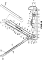
- Fig. 2 is a cross-sectional view showing the inner structure of the disc player.
- Fig. 3 is an exploded perspective view of the disc player.
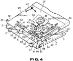
- Fig. 4 is a rear-side perspective view showing the cartridge holder.
- Fig. 5A is a plan view showing a shutter opening unit and the shutter opening and closure section shift unit provided on the upper surface of the cartridge holder.
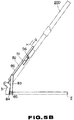
- Fig. 5B is a diagrammatic side elevation showing the cartridge holder rotated to the raised position.
- Fig. 6 is a perspective view of the keyboard cover.
- Fig. 7 is a partial perspective view showing the first cover attached to the main body of the disc player.
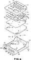
- Fig. 8 is a perspective view of the display section.
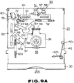
- Fig. 9A is a plan view showing the disc cartridge inserted into and held by the cartridge holder.
- Fig. 9B is a diagrammatic side elevation showing the rotational position of the cartridge holder relative to the chassis base plate with the disc cartridge inserted into and held by the cartridge holder.
- Fig. 10A is a plan view showing the state in which the cartridge holder accommodating the disc cartridge has been rotated towards the disc loading section.
- Fig. 10B is a diagrammatic side elevation showing the rotational position with respect to the chassis base plate of the cartridge holder being rotated towards the disc loading section.
- Fig. 11 is a cross-sectional view showing the disc cartridge loaded on the disc loading section.
- Fig. 12 is a perspective view showing the state in which the optical disc proper is loaded on the disc loading section and the cartridge holder is rotation towards the disc loading section.
- Fig. 13A is a perspective view of the disc player when in use, that is in the state of reading out and reproducing information signals.
- Fig. 13B is a perspective view showing the state in which the disc player is placed on the palm of the hand when in use.
- Fig. 14 is a perspective view of the disc player when out of use, with the first and second covers closed upon the main body of the disc player.
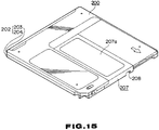
- Fig. 15 is a perspective view showing the upper surface of the disc cartridge loaded on an electronic equipment according to the present invention.
- Fig. 16 is a perspective view showing the lower surface of the disc cartridge.
- Fig. 17 is a perspective view showing the upper surface of the disc cartridge with the shutter being opened.
- Fig. 18 is a perspective view showing the lower surface of the disc cartridge with the shutter being opened.
- Fig. 19A is a perspective view showing a charging battery pack attached on a disc player.
- Fig. 19B is a perspective view showing a dry battery casing attached on a disc player.
- Fig. 20 is a perspective view showing a battery pack mounting plate provided on a disc player, a charging battery pack attached on the disc player and a battery casing.
- Fig. 21 is a plan view, shown partially in cross-section, showing the battery casing attached on the disc player.
- a disc cartridge comprised of a main cartridge body accommodating therein an optical disc with the information or data corresponding to a Japanese language dictionary or an English-Japanese dictionary recorded thereon or an optical disc proper with musical sound signals or the like recorded thereon may be selectively used as a recording medium, and in which the information or data read out and reproduced from the disc in the main cartridge body may be displayed on the display section, by way of realizing the function of reproducing the optical disc and the function of displaying the reproduced information simultaneously.
- the disc player includes a main body 3 having accommodated therein a disc rotating-driving unit 1 for rotationally driving ann optical disc contained in a main cartridge body of a disc cartridge, or an optical disc proper, and an optical pickup unit 2 functioning as information signal readout means for reading and reproducing information signals recorded on the optical disc rotationally driven by the unit 1.
- the main body 3 is constituted by a rectangular box-shaped cabinet 4 and a bottom plate 5 closing a bottom opening of the cabinet 4, as shown in Fig. 2.
- the main body 3 includes a disc loading section 6 on its upper surface which is sized to receive the disc cartridge accommodating therein an optical disc which is 8 cm in diameter, as shown in Fig. 1.
- the main body 3 is of a size that can be placed on the palm of a hand and is about 105 mm in width (W), about 135 mm is length (L) and about 45 mm in height (H).
- the disc rotating-driving unit 1 and the optical pickup 2 are mounted on a chassis base plate 7, obtained by punching from a metal plate, and are mounted within the cabinet 4 by means of this chassis base plate 7.
- the disc rotating-driving device 1 is constituted by a disc table 8 on which the optical disc is placed and which is rotationally driven along with the optical disc, and a spindle motor 9 rotationally driving the disc table 8.
- this spindle motor 9 has a spindle 10 projecting above the upper surface of the chassis base plate 7 and is mounted on the lower surface of the chassis base plate 7.
- the disc table 8 on which rests the optical disc is mounted on the distal end of the spindle 10 for rotation in unison with the spindle 10.
- a centering member 11 is provided at the center of the disc table 8 for fitting into a central opening of the optical disc for aligning the center of rotation of the disc table 8 with the center of the optical disc.
- This centering member 11 is mounted under the bias of a coil spring on the like so as to be movable along the axis of the spindle 10, so that, when the optical disc is placed on the disc table 8, the centering member 11 is fitted into the central opening of the disc, while being resiliently biased and deviated along the axis of the spindle, for bringing the central opening of the disc into alignment with the center of rotation of the disc table 8.
- the optical pickup unit 2 is supported by a feed screw 13 rotationally driven by a pickup feed motor 12 mounted on the lower surface of the chassis base plate 7 and a slide guide block mounted on the lower surface of the chassis base plate 7, so that the pickup unit 2 may be moved linearly along the radius of the disc placed on the disc table 8.
- the optical pickup unit 2 may be fed along the radius of the optical disc by the feed screw 13 being rotationally driven by the pickup feed motor 12.
- a buffer member 17 is interposed between the mounting piece 14 and the supporting piece 15 to prevent an impact or the like disturbances applied to the cabinet 4 from being transmitted from the cabinet to the chassis base plate 7 and obstructing the feed motion of the optical pickup device 2 or the disc rotation by the disc rotating-driving device 1.
- buffer member 17 is formed by rubber or the like elastic member and a coil spring 18 disposed therein to augment the buffer action of the buffer member.
- the buffer member 17 is supported with an engaging groove 17a on the central perimetral portion thereof fitted into a recess 14a in the mounting piece 14, such that, when the chassis base plate 7 is mounted on the cabinet 4, the buffer member is interposed between the mounting piece 14 and the supporting piece 15.
- the upper surface of the cabinet 4 on which rests the disc table 8 of the disc rotating-driving device 1 mounted on the chassis base plate 7 mounted in turn on the cabinet 4 functions as a disc loading section 6 on which to load the disc cartridge accommodating an optical disc placed on the disc table 8.
- positioning pins 20 and height setting pins 21 for setting the horizontal position and height level of the disc cartridge loaded on the disc loading section 6.
- a signal processing circuit for processing information signals read out from the optical disc by the optical pickup device 2 and an electrical circuit base plate 22 constituting an electrical circuit necessary for constituting a reproducing apparatus for a disc, such as a control circuit controlling the transfer of the optical pickup device 2.
- this electrical circuit base plate 22 is mounted by a set screw 24 to a depending boss 23 in the cabinet 4 along the bottom plate 5 of the cabinet 4.
- a cartridge holder 25 is mounted by the chassis base plate 7, on which the disc rotating-driving device 1 and the optical pickup device 2 have been mounted as described previously.
- This disc cartridge 25 is adapted for loading a disc cartridge 200 constructed as shown in Figs. 13 to 16 on the disc loading section 6 within the main body 3 and placing an optical disc 201 accommodated in the disc cartridge 200 on the disc table 8, and is mounted on the chassis base plate 7 so as to be turned between a lowered position covering the disc loading section 6 and an open or raised position opening the loading section 6 to enable the insertion or removal of the disc cartridge 200.
- the disc cartridge 200 loaded on the disc player of the present invention rotatably accommodates therein the optical disc 201 within a main cartridge body 202 is comprised on an upper half 203 and a lower half 204 abutted and connected to each other as shown in Figs. 15 and 16.
- the main cartridge body 202 includes, as shown in Figs. 17 and 18, an aperture 205 for opening a portion of the signal recording surface of the optical disc 201 outwards in the radial direction, and a disc table inserting aperture 206, which is formed at the center of the main cartridge body 202 so as to be contiguous to the aperture 205 to permit the entrance into the disc cartridge of the disc table 8 of the disc rotating-driving device 1 adapted for rotating the disc 201.
- a shutter 207 is movably mounted on the main cartridge body 202 for closing the apertures 205 and 206 to prevent dust and dirt from being intruded via apertures 205 and 206 into the main cartridge body 202 to contaminate the signal recording surface of the optical disc 201 accommodated therein.
- This shutter 207 is formed by bending a thin metal plate into the U shape and fitted to the main cartridge body 202 so as to cover the apertures 205 and 206 by an upper cover plate 207a and a lower cover plate 207b.
- the shutter 207 is biased by a shutter closure spring 210 for closing the apertures 205 and 206 during the non-use time when the disc cartridge 200 is not mounted within the present loading device.
- a pin engaging opening 208 engaged by a shutter opening/closing pin on a shutter opening arm of a shutter opening unit provided on the cartridge holder 25 in which the disc cartridge 200 is mounted, as will be explained subsequently.
- the shutter opening/closing pin is engaged with the pin engaging opening 208 and, when the disc cartridge 200 is further intruded into the cartridge holder 25, the shutter opening arm is rotated, so that the shutter 207 is moved to follow the rotation of the shutter opening arm against the bias of the shutter closing spring 210.
- the apertures 205 and 206 are opened, as shown in Figs. 17 and 18, under the movement of the shutter 207 against the bias of the shutter closure spring 210.
- the cartridge holder 25, into which the above described disc cartridge 200 is inserted and retained, is in the form of a flat box of a size to accommodate the disc cartridge 200, as shown in Figs. 3 and 4, and is formed on both sides thereof with cartridge supporting sections 26 and 27 for supporting both sides of the disc cartridge 200. These sections 26 and 27 are formed by bending the major surface 28 into the L-shape.
- the front side opening of the cartridge holder 25, which is perpendicular to these side sections 26, 27, functions as an insertion/removal opening 29 for the disc cartridge 200.
- a rest 30 is provided for slightly protruding from the front edge of the cartridge holder 25.
- This rest 30 is formed as a molded body of synthetic resin, similarly to the main cartridge body 202, and is mounted on the outer front perimeter of the cartridge holder 25 for surrounding the cartridge inserting/removal opening 20.
- the lower surface of the rest 30 towards the opening 29 is inclined to guide the cartridge 200 as it is introduced into the main cartridge body 25.
- the width of the insertion/removal opening 29 is lesser than the dimension of a diagonal line of the disc cartridge 200 inserted into and held by the cartridge holder 25 so that the disc cartridge 200 cannot be inserted into cartridge holder 25 in the oblique position.
- the cartridge holder 25 is rotatably supported by having the rear sides opposite to the cartridge inserting/removal opening 29 fulcrumed by a pair of holder mounting pieces 31, 31 provided on both rear sides of the chassis base plate 7. That is, the cartridge holder 25 is supported for rotation relative to the chassis base plate 7 by engaging-pivot shafts 33, 33 on the holder mounting pieces 31, 31 in mating engaging openings formed in a pair of upstanding support pieces 32, 32 on both rear sides of the cartridge holder 25.
- a disc clamper 35 for clamping the disc placed on the disc table 8 in cooperation with the disc table 8 to cause unitary rotation of the disc with the disc table 8 is mounted at approximately the center of the major surface 28 of the cartridge holder 25.
- the disc clamper 39 is supported by a clamper mounting plate 36 rotatably supported on the upper major surface 28 of the cartridge holder 25, and is adapted to be reciprocated into and out of the interior of the disc cartridge 25 by way of an opening 37 in the major surface 28.
- a clamper mounting plate 36 rotatably supported on the upper major surface 28 of the cartridge holder 25, and is adapted to be reciprocated into and out of the interior of the disc cartridge 25 by way of an opening 37 in the major surface 28.
- the disc clamper 25 is supported by the clamper mounting plate 36 by having a cylindrical section 39 on the upper surface of the clamper thrust plate 38 thrusting and supporting the optical disc introduced into the clamper mounting plate 36 to prevent the clamper from being extricated from the clamper mounting plate 36 by a flange 40 mounted on the upper end of a cylindrical section 39. That is, the disc clamper 35 is loosely supported by the clamper mounting plate 36 for free rotation and for movement axially within the extent of the cylindrical section 39.
- a permanent magnet 41 attracted to the disc table formed of a magnetic material such as metal is mounted on the side of the disc clamper 35 opposite to the disc table 8.
- the purpose of the magnet 41 is to ensure that, when the disc clamper 35 has clamped the optical disc in cooperation with the disc table 8, the optical disc performs a positive unitary rotation with the disc table 8.
- An engaging projection 35a engaging in a positioning engaging recess 8a formed at the center of the disc table 8 is provided at the center on the surface of the disc clamper 35 opposite to the disc table 8. When the disc clamper 35 has been attracted to the disc table 8, the engaging projection 35a is engaged with the positioning engaging recess 8a for bringing the center of rotation of the disc clamper 35 into coincidence with that of the disc table 8.
- the clamper mounting plate 36 supporting the disc clamper 35 is formed with a pair of supporting pieces 42, 42 having through-holes into which a supporting shaft 46 passed through and supported between a pair of supporting pieces 45, 45 formed integral with the major surface 28 of the cartridge holder 25, so that the plate 36 is supported for rotation relative to the major surface 28 of the cartridge holder 25 with the supporting shaft 46 as the center of rotation.
- the clamper supporting plate 36 is rotationally biased in the direction shown by an arrow A in Fig. 2 by a torsion coil spring 47 wound about the supporting shaft 46 so that the disc clamper 35 is protruded into the interior of the cartridge holder 25.
- the disc mounting plate 36 is rotated in the direction opposite to the direction shown by an arrow A in Fig. 2, by a lever 48 mounted on the upper major surface 28 of the cartridge holder 25, against the bias of the torsion coil spring 47, for receding the disc clamper 35 towards outside from within the cartridge holder 25. That is, when the cartridge holder 25 is at the raised position opening the disc loading section 6 to enable insertion or extraction of the disc cartridge 200, the clamper mounting plate 36 recedes the disc clamper 35 to a position of not obstructing the insertion or extraction of the disc cartridge into on out of the cartridge holder 25.
- the cartridge holder 25 is provided with a shutter opening and closure unit 50 for shifting a shutter 207 of the disc cartridge 200 inserted into and held by the cartridge holder 25 for opening the apertures 205 and 206 in the main cartridge body 202 for opening the signal recording surface and the perimeter of a central opening 201a of the optical disc 201 towards outside.
- the shutter opening and closure unit 50 is constituted by a shutter opening arm 51 rotated by the disc cartridge 200 inserted into the cartridge holder 25 for moving the shutter 207 against the bias of a shutter closing spring 210, a shutter opening arm rotating lever 53 biased by a tension spring 52 and adapted for rotating the shutter opening arm 51 to a reset position when the cartridge holder 25 has been rotated to the raised position, a locking lever 54 for locking the lever 53 for holding the shutter opening arm 51 at the rotational position opening the shutter 207 of the disc cartridge 200, and an unlocking lever 55 for releasing the locking of the lever 53 by the locking lever 54 by the rotation of the cartridge 25 to its raised position.
- the shutter opening arm 51 has an elongated arm section 51a, on the distal end of which is mounted a shutter opening and closing pin 56 engaging in a pin engaging opening 208 formed in a shutter 207 of the disc cartridge 200 and on the proximal side of which a fulcrum 57 for the cartridge holder 25 is formed by bending the proximal side.
- the shutter opening/closing arm 51 has its arm section 51a extending towards the inner side of the cartridge holder 25, so that the shutter opening and closing pin 56 faces the disc cartridge insertion and removal opening 29 of the cartridge holder 25, while the arm 51 also has the fulcrum 57 fulcrumed by a shaft 58 provided on the rear side of the cartridge holder 25, so that the arm 51 may be rotated in the directions shown by arrows B and C in Fig. 3, with the shaft 58 as the center of rotation.
- the shaft 58 is mounted at an L-shaped bent portion 59 at the rear side of the cartridge holder 25.
- the fulcrum 57 of the shutter opening and closing arm 51 is rotatably mounted by having the shaft 58 passed through a through-hole formed in the fulcrum 57.
- the lever 53 for rotating the shutter opening arm is mounted, with a pair of slide guide pins 61, 61 provided on the upper major surface 28 of the cartridge holder 2 engaging in elongated through-holes 62, 62 in the lever 53, so as to be slidable within the extent of these through-holes 62, 62.
- the lever 53 is biased in the direction shown by an arrow D in Fig. 5A by a tension spring 52 installed between a spring retainer 63 formed integrally with the major surface 28 of the cartridge holder 2 and a spring retainer 64 formed integrally with the lever 53.
- the shutter opening and closing arm 51 is connected to the lever 53 by having a rotation guide pin 67 provided on the lever 53 engaged in an elongated opening 66 formed in a lever connecting member 65.
- the shutter opening and closing arm 51 thus connected to the lever 53, is rotationally biased in a direction shown by an arrow C in Fig. 3 under the bias of torsion spring 52 which also biases the lever 53 in a direction shown by an arrow D in Fig. 5A.
- the shutter opening and closing arm 51 is kept under the bias of the tension spring 52 under a condition in which it has been moved to a position in which the shutter opening and closure pin 56 faces to and can be engaged in a pin engaging opening 28 formed in the shutter 207 of the disc cartridge 200 inserted into the disc cartridge 200.
- a locking pawl 68 engaging in a locking pin 67 provided on one end of locking lever 54 is provided on one side of the foremost part of the lever 53.
- This locking pawl 68 is engaged with the locking pin 67 when the disc cartridge 200 is introduced into the cartridge holder 25, the shutter opening and closing arm 51 is rotated by the disc cartridge 200 in the direction shown by an arrow B in Fig. 3 for opening the shutter 207, and the lever 53 is moved in the direction shown by an arrow E in Fig. 5A to follow the rotation of the shutter opening and closing arm 51 to maintain the lever 53 at a position in which it has been moved against the bias of the tension spring 52 to maintain the shutter opening and closing arm 51 at a position in which it has opened the shutter 207.
- the locking lever 54 for locking the lever 53 at the position in which it has been moved against the bias of the tension spring 52 is chevron-shaped and has the locking pin 67 at one end for engaging with the locking pawl 68 of the lever 53 and a pin 69 at the other end which is thrust by the unlocking lever 55.
- the locking lever 54 is mounted, with the locking pin 57 facing to the locking pawl 68 of the lever 53 and with a supporting shaft 70 on the major surface 28 of the cartridge holder 25 introduced into a central through-hole, not shown, of the locking lever 54, so that the lever 54 may be rotated with the supporting shaft 70 as the center of rotation.
- the locking lever 54 is rotationally biased in a direction shown by an arrow F in Fig.
- a torsion coil spring 72 which is placed about the supporting shaft 70 and has one end retained by the locking pin 67 and the other end retained by a spring retainer 71 formed integrally with the major surface 28 of the cartridge holder 25.
- the rotational bias position of the locking lever 54 by the torsion coil spring 72 is delimited by a rotation delimiting portion on one end of the locking lever 54 engaging in a rotation delimiting opening 78 formed in the major surface of the cartridge holder 25.
- the unlocking lever 55 for releasing the locking of the lever 53 by the locking lever 54 as a result of the rotation to the raised position of the cartridge holder 25 is mounted on a slide lever 82 by having a pair of slide guide pins 80, 80 on the major surface 28 of the cartridge holder 2 engaged in elongated through-holes 81, 81 of the slide lever 82, as shown in Fig. 5A, so that the slide lever 82 may be slid within the extent of the through-hole 81, 81 in the fore-and-aft direction of the cartridge holder 25 which is at right angles to the movement direction of the lever 53.
- Fig. 5A The unlocking lever 55 for releasing the locking of the lever 53 by the locking lever 54 as a result of the rotation to the raised position of the cartridge holder 25 is mounted on a slide lever 82 by having a pair of slide guide pins 80, 80 on the major surface 28 of the cartridge holder 2 engaged in elongated through-holes 81, 81 of the slide lever 82,
- this slide lever 82 is connected to the chassis base plate 7 via a lever 83 by means of which the lever 82 may be slid in the directions shown by arrows G and H in Fig. 5A in association with the rotation of the cartridge holder 25.
- the lever 83 interconnects the slide lever 82 with the chassis base plate 7 by having one end fulcrumed by a supporting shaft 85 on a mounting member 84 provided on one side of the chassis base plate 7 and the other end fulcrumed by a supporting shaft 87 on a mounting member 86 provided on one side of the lever 83.
- the unlocking lever 55 mounted on the slide lever 82 is molded from synthetic resin, and is in the form of a letter U, with a pin thrusting arm section 88 for thrusting a pin 69 on the locking lever 54 lying in opposition to a resilient arm section 89.
- An inclined cam section 88a for thrusting the pin 69 is formed on the outer lateral surface of the pin thrusting arm section 88.
- the unlocking lever 55 is mounted by having a web section interconnecting the arm sections 88, 89 fulcrumed by a supporting shaft 90 provided on slide lever 82 and by having the ends of the arm sections 89, 88 retained by retainers 91, 92 formed integrally with the slide lever 82.
- the unlocking lever 55 mounted on the slide lever 82 thrusts the pin 69 by the inclined cam section 88a to rotate the locking lever 54 in a direction opposite to the direction shown by an arrow A in Fig. 5 against the bias of the torsion coil spring 72 for disengaging the locking pin 67 from the locking pawl 68 of the lever 53.
- the unlocking lever 55 is rotated at this time about supporting shaft 90 of the pin thrusting arm section 88 whilst the resilient arm section 89 is deformed resiliently.
- the resilient arm section 89 functions as a limiter to permit stable rotation of the locking lever 54.
- the cartridge holder 25 is also provided with a unit 93 for bringing the disc clamper 35 into and out of contact with the disc table 8 in association with the rotation of the cartridge holder 25 to its raised and lowered positions.
- This unit 93 operates to rotate the clamper mounting plate 36 in association with the rotation of the cartridge holder 25 to reciprocate the disc clamper 35 supported by the clamper mounting plate 36 into and out of the cartridge holder 25 to bring the disc clamper into and out of contact with the disc table 8, and is constituted by a clamper mounting plate rotating lever 48 connected to the slide lever 82 which is slid by the rotation of the cartridge holder 25.
- the clamper mounting plate rotating lever 48 is mounted by having its central portion fulcrumed by a supporting shaft 94 on the major surface of the cartridge holder 25 and by having rotation guide pin 96 on the slide lever 82 engaged in a rotation guide opening 95 formed in the lever 48.
- the lever 48 thus mounted on the major surface 48 of the cartridge holder 28 is rotated in the directions shown by arrows I and J in Fig. 5A, about the supporting shaft 94 as the center of rotation, by the sliding movement of the slide lever 82 in the direction shown by the arrows G and H in Fig. 5A.
- the foremost part of the lever 48 is formed with a clamper mounting plate rotating section 97 for rotating the clamper mounting plate 36 as a result of the rotation of the lever 48.
- This rotating section 97 is formed as an arc of a circle extending along the direction of rotation of the lever 48.
- the rotating section 97 is constituted by an inclined ride guide surface 97a opposite to a ride guide portion 98 formed integrally with the clamper mounting plate 36 and a rotating surface 97b of a predetermined height continuous to the guide surface 97a.
- the rotating lever 48 is connected to the slide lever 82 in such a manner that, when the cartridge holder 21 has been rotated to its lower position, the inclined guide surface 97a abuts on and faces to the ride guide portion 98 without the rotating section 97 riding on the guide portion 98 of the clamper mounting plate 36. That is, when the cartridge holder 25 has been rotated to the lowered position, the rotating lever 48 operates in such a manner that the disc clamper 35 is attracted towards the disc table 8 to clamp the optical disc in cooperation with the disc table 8.
- a shutter arm shift unit 99 as the shutter opening member shift means for shifting the shutter opening arm 51 to a position of not obstructing the rotation of the optical disc placed on the disc table 8 even if the disc cartridge 200 is not loaded.
- the shutter opening arm shift unit 99 is provided with a shutter opening arm shift lever 100 rotated by the rotation of the cartridge holder 25 towards below to cause the sliding of the lever 53 in the direction shown by an arrow E in Fig. 5A against the bias of the torsion spring 52 to shift the shutter opening arm 51 in the direction shown by an arrow B in Fig. 3.
- the shift lever 100 is made up of an connecting arm section 100a connected to slide lever 82 and a lever operating arm section 100b engaging with a thrust pin 101 provided halfway on the lever 53.
- the disc player according to the present invention is provided with a keyboard cover 111 constituting the first cover in conjunction with the cartridge holder 25.
- a keyboard cover 111 constituting the first cover in conjunction with the cartridge holder 25.
- the surface of the keyboard cover 111 which faces upwards when the keyboard cover is lowered to cover the disc loading section 6 provided on the upper surface of the main body 3 is provided with an operating section carrying an array of operating keys 112 adapted for controlling the read-out operation of information signals recorded on the optical disc loaded on the disc loading section 6 for reading out and reproducing the desired information from the optical disc.
- an operating section carrying an array of operating keys 112 adapted for controlling the read-out operation of information signals recorded on the optical disc loaded on the disc loading section 6 for reading out and reproducing the desired information from the optical disc.
- this operating section is constituted by a resilient operating keyboard 113 carrying a large number of operating keys 112 resiliently deviated when thrust, and a key switch mounting plate 114, which is a printed circuit board carrying a switching section which may be turned on and off by thrusting the operating keys 112.
- the operating keyboard 113 is mounted on the inner surface of the keyboard cover 111.
- the operating keys 112 are passed through through-holes 115 formed in the keyboard cover 111 so as to be protruded above the upper surface of the keyboard cover 111.
- the key switch mounting plate 114 is mounted on the inner surface of the keyboard cover 111 so as to be superimposed on the operating keyboard 113.
- the operating keyboard 113 and the key switch mounting plate 114 are fixedly supported by a cover plate 116 mounted on the inner surface of the keyboard cover 111 so as to cover the board 113 and the mounting plate 114.
- the cover plate 116 is secured by a set screw 116a to the keyboard cover 111.
- the operating keys 112 constituting the operating section include alphabet keys 112a displaying alphabetical letters, a cursor shift key 112b for shifting a cursor pointing to one of a plurality of select data items read out from the optical disc 201 so as to be displayed on a display section as described later, a plurality of selection keys 112c, 112d for selecting the selected data item pointed to by the cursor shifted by the operation of the cursor shift key 112b, a plurality of function select keys 112e for selecting the data readout function of the disc layer, and character display changeover keys 112f, 112g.
- the keyboard cover 111 having the operating section comprised of an array of the operating keys 112 or its upper surface is mounted for rotation relative to the main body 3 by having rotation supporting plates 121, 121 or both rear sides fulcrumed by supporting shafts 123, 123 on supporting plates 119, 119 on the opposing inner surfaces of the cover mounting sections 117, 118 on both rear sides of the cabinet 4 of the main body 3, with the keyboard cover 111 being closed upon the upper surface of the cartridge holder 25 supported by the main body 3.
- a toggle spring 125 is interposed between one of the supporting plates 119 and the rotation supporting plate 122. As shown in Fig.
- the toggle spring 125 is mounted by having the foremost part of one of the arm sections 125a engaged in an opening 126 formed in the rotation supporting plate 122 of the keyboard cover 111 and by having the foremost part of the other arm section 125b retained by a retention pin 127 of the supporting plate 119.
- the keyboard cover 111 is rotated in the opening position or closure position relative to the main body 3, the keyboard cover 111 is rotationally biased towards these opening or closure positions, by the provision of the toggle spring 125, to maintain these opening or closure positions.
- the cartridge holder 25 is connected to the keyboard cover 111 so as to be rotated in association with the movement of the keyboard cover 111.
- the cartridge holder 25 is connected to the keyboard 111 by having engaging pieces 130, 130 on both opposing inner sides of the keyboard cover 111 engaged with mating engaging pieces 128, 128 on both sides of the major surface 28 of the cartridge holder 25.
- the keyboard cover 111 and the cartridge holder 25 thus mounted in a mutually superimposed manner on the main body 3 constitute a first cover 110 which is rotated in unison by the rotating operation of the keyboard cover 111.
- the first cover 50 is rotated in unison, with the keyboard cover 111 superimposed on the cartridge holder 25, whereas, during opening, the cartridge holder 25 is rotated to follow the keyboard cover 111, with the engaging pieces 130, 130 engaging with the mating engaging pieces 128, 128.
- the disc player of the present invention is provided with the cartridge holder 25 to provide for loading of the disc cartridge 200, it is unnecessary to provide the cartridge holder 25 if the optical disc proper is used as the recording medium.
- the disc clamper 35 adapted for clamping the optical disc in cooperation with the disc table 8 may be mounted directly on the inner surface of the keyboard cover 111.
- the first cover 110 is constituted only by the keyboard cover 111.
- the main body 3 constituting the electronic equipment of the present invention is fitted with a second cover 132 operating as an outer cover.
- the second cover 132 functions as a display panel for displaying the information read out and reproduced from the optical disc loaded in the electronic equipment according to the present invention.
- a display section 133 is provided on the inner surface of the second cover 132, as shown in Figs. 1 and 2.
- This display section 133 is constituted by a display panel 134 formed by, for example, a liquid crystal display device or LCD arranged on the inner lateral surface of the second cover 132.
- This display panel 134 is secured to the inner surface of the second cover 132 by a metal fitting 134c secured to the second cover 132 by an adhesive sheet 134a and a set screw 134b.
- the display panel 134 is covered by a display panel cover plate 135 having an opening 135a in register with the display portion of the panel 134.
- a transparent plate 135b such as a glass plate, is placed over the opening 135a by the interposition of an adhesive sheet 135c.
- the second cover 132 is rotatably supported on the opposing upper inner lateral sides of upright bracket 117, 118 on the rear side of the cabinet 4 by which the first cover 110 is fulcrumed, with the second cover 132 being closed upon the first cover 110 rotatably supported by the main body 3.
- the second cover 132 is mounted by having the narrow proximal side fitted to the brackets 117, 118, and is rotatably mounted on the cabinet 4 by having friction pins 132a, 132b on the proximal side thereof fulcrumed by bearings 117a, 118a provided on the brackets 117, 118.
- the second cover may be maintained at any desired angular position.
- a locking member 138 engaging with a locking portion formed in the main body 3.
- the second cover 132 superimposed on the first cover 110 to cover the main body 3 may be maintained reliably in the closure position.
- the first cover 110 and the cartridge holder 25 interlocked with the first cover 110 may be positively maintained at the closure position to prevent inadvertent opening.
- a start/stop button 140 operating as a power source switch for on/off control of the power source of the disc player in its entirety, a playback key 142 for designating the playback of an audio optical disc 220 which is utilized when the optical disc 220 is loaded in the disc player, a fast feed key 143 for designating fast feed in the forward direction, a reverse fast feed for designating the fast feed in the reverse direction, and a sound volume adjustment key 145.
- a jack 146 for outputting voice signals
- a jack 147 for inputting an external power source
- a contrast adjustment knob 148 for display panel 134 for display panel 134
- the locking member 138 is operated to release the locking of the second cover 132 with respect to the main body 3 to open the second cover 132.
- the first cover 110 is then opened, and the cartridge holder 25 is brought to its raised position in which the cartridge holder 25 is spaced apart from the disc loading section 6, as shown in Figs. 1 and 5B.
- the lever 53 With the cartridge holder 25 thus rotated to its raised position, the lever 53 has been shifted in the direction shown by an arrow D in Fig. 5A, under the bias of the torsion spring 52.
- the shutter opening and closing arm 51 is rotated towards the disc clamper 35, as shown in Fig. 3, and the shutter opening and closing pin 56 is at a position facing the pin engaging opening 108 formed in the shutter 207 of the disc cartridge 200 introduced into the disc cartridge 25.
- the shutter opening and closure pin 56 is engaged in the pin engaging opening 108 of the shutter 207.
- the shutter opening arm 51 is thrust by the disc cartridge 200 and thereby rotated in the direction shown by an arrow B in Fig. 5A, with the fulcrum 57 as the center of rotation.
- the shutter opening arm 51 reaches a state in which it has been rotated to the rear end of the cartridge holder 25 and the lever 53 shifted by the shutter opening arm 51 operates to maintain the shutter opening arm 51 at the position of opening the shutter 207, with the locking pawl 68 engaging with and locking the locking pin 67 of the locking lever 54, as shown in Fig. 7A.
- the cartridge holder is kept at its raised position, without being rotated, while the slide lever 82 is also not slid, the lever 83 not being rotated, as shown in Fig. 9A.
- the disc cartridge 200 is retained within the cartridge holder 25, under the supporting force from the shutter opening and closure arm 51, since the lever 53 is locked by the locking lever 54 and the arm 51 holds the shutter in the opened position.
- the cartridge holder 25 When the first cover member 110 is rotated from the state in which the disc cartridge is inserted and the shutter 207 is opened in a direction of closing the disc loading section 6 of the main body 3, the cartridge holder 25 is also rotated towards below in a direction closing the disc loading section 6.
- the disc table 8 When the cartridge holder 25 is rotated to a lowered position of closing the disc loading section 6, the disc table 8 is intruded into the inside of the main cartridge body 202 by way of the opened aperture 206 in the main cartridge body 202 and the optical disc 201 accommodated in the main cartridge body 202 is placed on the disc table 8.
- the optical disc 201 is placed on the disc table 8 with its central opening engaged by the centering member 11 for assuring centering of the disc relative to the disc table 8.
- the disc cartridge 200 is loaded on the disc loading section 6 whilst it is positioned both horizontally and vertically by the positioning pins 20 and the height setting pins 21 provided on the chassis base plate 7.
- the slide lever 82 is slid in the direction shown by an arrow G in Figs. 10A and B by means of lever 83.
- the slide lever 82 is biased at this time by tension spring 82a in the direction shown by an arrow G in Fig. 10A and hence may be slid positively in the direction shown by an arrow G in Fig. 10A.
- the disc clamper 35 is attracted towards the disc table 8, under the magnetic attraction by the magnet 41, for clamping the optical disc 201 on the disc table 8 in cooperation with the disc table 8, as shown in Fig. 9, for enabling the optical disc 201 to be rotated in unison with the disc table 8.
- an optical disc 220 not accommodated in the disc cartridge 200 may be loaded in the disc loading section 6.
- the disc loading section 6 provided on the upper surface of the main body 6 is in the opened state.
- the optical disc 220 is loaded on the disc table 8 provided in the disc loading section 6.
- the cartridge holder 25 is also rotated towards the lower position of closing the disc loading section 6.
- the slide lever 82 is slid in the direction when by an arrow G in Fig. 10A, by means of the lever 83, as in the case of loading the disc cartridge 200, as explained previously.
- the lever 53 is slid in the direction shown by an arrow E in Fig. 10A against the bias of the tension spring 52.
- the shutter opening arm 51 In association with the sliding of the lever 53, the shutter opening arm 51 is rotated in the direction shown by an arrow B in Fig. 12, with the fulcrum 57 as the center of rotation.
- the shutter opening and closing arm 51 in its entirety, inclusive of the shutter opening and closure pin 56 has been moved out of the extent of rotation of the optical disc 220 placed on the disc table 8, that is, to a position not obstructing the rotation of the optical disc 201, as shown in Fig. 12.
- the lever 53 When the closure state of the first cover 110 is reached, in which the shutter opening and closing arm 51 is moved to a position not obstructing the rotation of the optical disc 201, the lever 53 operates to maintain the shutter opening and closing arm 51 at a position of not obstructing the rotation of the optical disc 220, with the locking pawl 68 being engaged and locked by the locking pin 67.
- the first cover 110 covers the disc loading section 6 to close the main body 3, as shown in Fig. 13A.
- the keyboard 113 on the upper surface of the first cover 110 is opened to the upper surface of the main body 3.
- the second cover 132 is rotated and set at a suitable angle so that the display section 133 provided on the inner surface of the second cover 132 is opened to outside, as shown in Fig. 13A.
- the start-stop button 140 on the front side of the main body 3 is actuated to start the rotation of the optical disc 201 to enable the information signals recorded on the optical disc 201 to be read out and reproduced.
- the operating key 112 on the keyboard 113 is also actuated to read out the desired information.
- the desired information read out and reproduced from the optical disc 201 is then displayed as the image information on the display section 133 of the second cover 132.
- the disc player may be used as it is held on the palm of the hand, even when the second cover member 132 is opened for use, as shown in Fig. 13A.
- the start/stop button 140 is actuated to stop the operation of the disc player.
- the first cover 110 is then rotated in the opening direction.
- the cartridge holder 25 follows the rotation of the first cover 110 in the opening direction so that the cartridge holder 25 reaches the raised position relative to the main body 3.
- the slide lever 82 is slid in the direction shown by an arrow H in Fig. 10A.
- the lever 48 connected to the slide lever 82 is rotated in the direction shown by an arrow J in Fig.
- the disc clamper 35 which has so far clamped the optical disc in cooperation with the disc table 8, is disengaged from the disc table 8 to release the clamping of the disc 201, at the same time that the disc clamper 35 is receded outwards from within the cartridge holder 25.
- the shutter opening arm 51 connected to the lever 53 is rotated in the direction shown by an arrow C in Fig. 9A, with the fulcrum 57 as the center of rotation, for ejecting the disc cartridge 200 out of the cartridge holder 25.
- the shutter 207 of the disc cartridge 200 is moved by the rotational operation in the direction of the arrow C in Fig. 9A and under the bias of the shutter closure spring 210 to close the apertures 205 and 206 of the main cartridge body 202.
- a mistaken insertion inhibit member 142 is provided on the cartridge holder 25 to prevent the mistaken insertion of the disc cartridge 200 as well as to thrust the one lateral surface of the disc cartridge 200 inserted into the disc cartridge 200 to prevent the disc cartridge 200 from being ejected inadvertently out of the cartridge holder 25 at the time of ejection.
- the mistaken insertion inhibit member 142 is constituted by a torsion coil spring which, as shown in Fig.
- the disc cartridge 200 is mounted to a mounting boss 143 on the major surface 28 of the cartridge holder 28, and has an L-shaped mistaken insertion inhibit end section 142a protruded into the inside of the cartridge holder 25 and a retention end section 142b retained by a retainer 144 on the major surface 28 of the cartridge holder 28.
- the disc cartridge 200 When the disc cartridge 200 is inserted into the cartridge holder 25 from an incorrect direction, the disc cartridge 200 has a portion thereof retained by the end section 142a to prevent the correct insertion of the disc cartridge 200 into the disc cartridge 200.
- the end section 142a thrusts and supports one lateral side of the main cartridge body 202 to prevent inadvertent ejection of the disc cartridge 200 from the disc cartridge 25.
- the disc cartridge 200 With the disc cartridge 200 thus ejected out of the cartridge holder 25, the disc cartridge 200 is taken out manually from the cartridge holder 25 to terminate the ejecting operation.
- the first cover 110 When the optical disc 201 is mounted, the first cover 110 is opened to open the disc loading section 6 of the main body 3. Since the optical disc 201 then faces the outside, it may be grasped with hand or finger and removed from the disc table 8 by way of performing the ejecting operation.
- the operation of the disc clamper 35 or the shutter opening arm 51 is similar to that when ejecting the disc cartridge 200, so that the direction therefor is omitted for simplicity.
- the first cover 110 is closed upon the disc loading section 6 on the upper surface of the main body 3.
- the second cover 132 is then rotated towards the main body 3 and brought to a closure position on the first cover 110, whereby the operating keys 112 on the upper surface of the first cover 110 is covered by the second cover 132.
- the display section 133 provided on the second cover 132 is positioned on the inner and folded upon the main body 3. With the first and second covers 110, 132 thus brought to the closure state, the covers 110 and 132 are folded or closed unitarily upon the main body 3 into a compact casing which may be transported freely in a bag or the like.
- the above described disc player may be driven not only by a commercial d.c. source (9V) by means of a jack 147, but also by a charging battery or a dry battery removably mounted on the main body 3.
- a commercial d.c. source (9V) by means of a jack 147, but also by a charging battery or a dry battery removably mounted on the main body 3.
- a charging battery pack 151 or a dry battery casing 152 may be selectively loaded on the back side of the main body 103 of the disc player as shown in Fig. 19A and 19B.
- a battery pack mounting plate 153 is mounted by a set screw 154 for detachably mounting the charging battery pack 151 or the dry battery casing 152 thereto.
- the mounting plate 153 is formed with a plurality of engaging pieces 156 engaged by a corresponding plurality of engaging lugs 155 formed on an abutment surface of the battery pack 151 or the casing 152 to the mounting plate 153.
- These engaging piece 156 are formed on the confronting side edge of the mounting plate 153 as convex-shaped pieces by forming slots or grooves on the back side of the mounting plate 153 in continuation to concave-shaped recesses 157 into which the lugs 155 are intruded.
- the mounting plate 153 is also formed with an engaging recess 158a engaged by a locking pawl 158 provided on the battery pack 151 or the casing 152.
- connection terminal plate 161 for establishing electrical connection with a terminal pin 161 on the battery pack 151 or on the dry battery casing 152 on loading the battery pack 151 or the dry battery casing 152 is provided on the back side of the main body 3.
- This connection terminal plate 161 is opened to outside by means of an opening 162 formed in the battery pack mounting plate 153.
- the engaging lugs 155 engaging with the engaging pieces 156 of the battery pack mounting plate 153 provided on the battery pack 151 or the dry battery casing 152 are formed on the upright lateral side of a recess 163 formed on the abutting surface against the mounting plate 153, as shown in Fig. 20.
- the locking pawl 158 is provided on the battery pack 151 or on the dry battery casing 152 so as to be intruded into or receded from the recess 163 by way of a through-hole 164 formed in the recess 163. As shown in Fig. 21, the locking pawl 158 is formed at the distal end of a locking lever 159.
- the locking lever 159 having the end locking pawl 158, is arranged in, for example, the dry battery casing 152, as shown in Fig. 21.
- the locking lever 159 is substantially L-shaped and accommodated in the dry battery casing 152 with an end thrust section 160 facing an opening 161 formed on one end face of the dry battery casing 152.
- the locking lever 159 is arranged within the casing 152 with a guide pin 163 on the casing 152 introduced through a through-hole 162 in the lever so that the lever 159 may be reciprocally supported for introducing or receding the locking pawl 158 into on out of the recess 163 as the lever is guided by the guide pin 163.
- the locking lever 159 is biased by a compression coil spring 164 placed about the guide pin 163 so that the end locking pawl 158 is intruded into the recess 163.
- the locking lever provided in the charging battery pack 151 is of a similar construction as that provided in the dry battery casing 152, so that the detailed description thereof is omitted for simplicity.
- a pair of biasing arms 165, 166 for resiliently biasing the pack 151 or the casing 152 away from the main body 3 are provided on an abutting surface of the pack 151 or casing 152 against the battery pack mounting plate 153.
- a plurality of terminal pins 160 for establishing electrical contact with the connection terminal plate 161 provided on the main body 3 is also provided for protruding into the recess 163, as shown in Fig. 20.
- These terminal pins 160 are biased by springs, not shown, for protruding into the recess 163, while being mounted for reciprocation within the recess 163.
- the above described charging battery pack 151 or the dry battery casing 152 are slid in the direction shown by an arrow X in Fig. 21, with the engaging lugs 155 in register with the concave recesses 157 in the battery pack mounting plate 153 and with the engaging lugs 155 engaging with the engaging pieces 156, so that, as shown in Fig. 20, the engaging lugs 155 are engaged with the engaging pieces 156, while the locking pawl 158 is engaged in the engaging recess 158a, as shown in Fig. 21.
- the charging battery pack 151 or the dry battery casing 152 is loaded in position in the main body 3.
- the terminal pins 160 are electrically contacted with the connection terminal plate 161 so that the power may be supplied to the main body 3 from the battery in the charging battery pack 151 or in the dry battery casing 152.
- the charging battery pack 151 has a width w1 equal to the width W of the main body, or 105 mm, a length l1 equal to 29 mm and a height h1 equal to 41 mm.
- the dry battery casing 152 has a width w2 equal to the width W of the main body, or 105 mm, a length l2 equal to 38 mm and a height h2 equal to 41 mm.
- the thrusting section 160 is thrust in the direction shown by an arrow Y in Fig. 21 for shifting the locking lever 159 against the bias of a compression coil spring 164.
- the terminal locking pawl 158 is receded out of the recess 163 for disengaging the battery pack mounting plate 153 from the engaging recess 158a.
- the thrust section 160 is thrust manually for sliding the charging battery pack 151 or the dry battery casing 152 in the direction shown by an arrow X in Fig.
- the charging battery pack 151 or the dry battery casing 152 are biased at this time by the biasing arms 165, 166 in a direction away from the main body 3, so that they may be detached positively from the main body 3 while the terminal pins 160 are protected from possible damages simultaneously.
Abstract
Description
- This invention relates to a disc player for reading out and reproducing information signals recorded on an information disc, such as an optical disc, and for displaying the read out and reproduced information signals on a display section, and a loading device whereby the information disc, such as an optical disc, on a disc table, in which both a disc proper and a disc cartridge comprised of a disc and a cartridge accommodating the disc therein may be loaded on the disc table.
- An optical disc has so far been used as a recording medium for recording musical sound information signals, image information signals or the like information signals.
- The optical disc is comprised of a base plate of a synthetic resin, such as a transparent polycarbonate resin, a recording layer formed on the base plate, and a layer of a transparent synthetic resin formed on the recording layer. Such optical disc exhibits sufficient mechanical strength as compared with the magnetic disc or the like formed by a film sheet as the base material. The recording layer covered by the synthetic resin exhibits sufficient durability against dust and dirt. Thus the so-called compact disc, which is an optical disc on which musical sound signals or the like are recorded, is handled as a disc per se, and loaded by itself on a disc player.
- On the optical disc, information signals are recorded at a higher recording density. The information signals may be rewritten with certain optical discs, or with magneto-optical discs operating under the photomagnetic effects. With these discs, deposition of only a small amount of dust and dirt on the signal recording surface results in dropout in recording or reproduction of the information signals to render it impossible to maintain satisfactory recording and/or reproducing characteristics.
- For this reason, this type of the optical disc is accommodated in the main cartridge body and loaded in this state on the disc player.
- Meanwhile, the disc player or the like apparatus in which the optical disc per se is used as the recording medium is designed so that only the disc per se may be loaded, whereas the disc player in which the disc cartridge comprised of a main cartridge body and an optical disc accommodated therein is used as the recording medium is designed so that only the disc cartridge may be loaded, while the disc proper cannot be loaded.
- In a disc player in which the optical disc is used as the recording medium, it is presently tried to enable information signals recorded on at least a plurality of optical discs to be read out and reproduced through standardization of the recording formats for these different optical discs.
- On the other hand, it is also tried to develop a disc player for which both the optical disc proper or the disc cartridge may be used as the recording medium.
- The above described disc player of the type in which information signals such as Japanese language dictionary data or the English-Japanese dictionary data are recorded on the optical disc, and desired data are read out from the disc so as to be displayed on the display section, is currently in use.
- Such disc player is constituted by a disc drive unit adapted for rotating an information disc such as an optical disc on which the predetermined information is recorded, and reading out and reproducing the information recorded on the disc, a keyboard device for selecting the desired information to be read and reproduced from the information recorded on the disc, and a display device for displaying the information read out from the disc as, for example, the letter or character information.
- Meanwhile, the conventional disc reproducing apparatus is constituted by a disc drive device, a keyboard device and a display device, there separate devices being put together and used as a desk type unit. The devices making up the disc reproducing apparatus tend to be bulky in size and hence cannot be adapted as portable devices.
- On the other hand, by reason of the drastically improved recording density in information discs, such as optical discs, the information corresponding to a voluminous Japanese language dictionary or English-Japanese dictionary may now be recorded on an optical disc which is 8 cm in diameter.
- Thus a demand is raised for an apparatus whereby a small optical disc on which information signals have been recorded at a high recording density may be accessed and the desired information may be read out and reproduced easily at a desired place so as to be displayed as visual information on a display device.
- Disc players for playing magnetic discs in cartridges are known, for example as described in document EP-A-0,194,138. However, it does not allow the playing of a disc which is not in a cartridge.
- It is an object of the present invention to provide a disc loading device in which an optical disc alone or a disc cartridge may be used as the recording medium.
- It is another object of the present invention to provide a disc loading device enabling an optical disc alone or a disc cartridge to be loaded on the disc recording and/or reproducing apparatus.
- The disc loading device according to the present invention comprises:
a cartridge holder supported movably between a raised position and a lowered position relative to a disc table provided for rotationally driving a disc placed thereon, on a main body provided with said disc table, said cartridge holder being designed for insertion therein of a disc cartridge rotatably accommodating a disc, and for holding said disc cartridge;
a disc clamper for clamping a disc placed on said disc table when said cartridge holder is lowered, in cooperation with said disc table; and
shutter opening means for moving a shutter to open and close an aperture formed in said disc cartridge, by insertion and removal of said disc cartridge into and from said cartridge holder; characterised by further comprising
shifting means for shifting said shutter opening means in association with the movement of said cartridge holder to said lowered position to a position of not obstructing the rotation of a disc placed on said disc table. - With the above described disc loading apparatus, when the disc cartridge is inserted into the cartridge holder, the shutter of the disc cartridge is opened by a shutter opening and closing unit provided on the cartridge holder. When the cartridge holder thus inserted into and held by the cartridge holder is lowered, the disc table is intruded into the main cartridge body by means of a disc table inserting aperture which has been opened by the opening of the shutter, and the disc is placed on the disc table, at the same time that the disc clamper is intruded into the main cartridge body by way of the disc table inserting aperture to clamp the disc by the disc table and the disc clamper to permit the rotation of the disc in unison with the disc table.
- When the cartridge holder is lowered without inserting the disc cartridge, the shutter opening member is receded by the shutter opening member shifting means, in association with the descent of the cartridge holder, to a position not obstructing the rotation of the disc placed on the disc table. That is, since the shutter opening member has been shifted to a position not obstructing disc rotation even when the cartridge holder should be lowered towards the disc table without inserting the disc cartridge into the cartridge holder, the disc proper may be placed in advance on the disc table.
- The present invention also provides a disc player comprising a disc loading device as mentioned above, reproducing means for reproducing information from a loaded disc, and a display section for displaying information reproduced by said reproducing means.
- The above and other objects, features and advantages of the present invention will become more apparent from the following description especially when read in conjunction with the accompanying drawings.
- Fig. 1 is a perspective view of a disc player according to the present invention, with the first and second covers being opened.
- Fig. 2 is a cross-sectional view showing the inner structure of the disc player.
- Fig. 3 is an exploded perspective view of the disc player.
- Fig. 4 is a rear-side perspective view showing the cartridge holder.
- Fig. 5A is a plan view showing a shutter opening unit and the shutter opening and closure section shift unit provided on the upper surface of the cartridge holder.
- Fig. 5B is a diagrammatic side elevation showing the cartridge holder rotated to the raised position.
- Fig. 6 is a perspective view of the keyboard cover.
- Fig. 7 is a partial perspective view showing the first cover attached to the main body of the disc player.
- Fig. 8 is a perspective view of the display section.
- Fig. 9A is a plan view showing the disc cartridge inserted into and held by the cartridge holder.
- Fig. 9B is a diagrammatic side elevation showing the rotational position of the cartridge holder relative to the chassis base plate with the disc cartridge inserted into and held by the cartridge holder.
- Fig. 10A is a plan view showing the state in which the cartridge holder accommodating the disc cartridge has been rotated towards the disc loading section.
- Fig. 10B is a diagrammatic side elevation showing the rotational position with respect to the chassis base plate of the cartridge holder being rotated towards the disc loading section.
- Fig. 11 is a cross-sectional view showing the disc cartridge loaded on the disc loading section.
- Fig. 12 is a perspective view showing the state in which the optical disc proper is loaded on the disc loading section and the cartridge holder is rotation towards the disc loading section.
- Fig. 13A is a perspective view of the disc player when in use, that is in the state of reading out and reproducing information signals.
- Fig. 13B is a perspective view showing the state in which the disc player is placed on the palm of the hand when in use.
- Fig. 14 is a perspective view of the disc player when out of use, with the first and second covers closed upon the main body of the disc player.
- Fig. 15 is a perspective view showing the upper surface of the disc cartridge loaded on an electronic equipment according to the present invention.
- Fig. 16 is a perspective view showing the lower surface of the disc cartridge.
- Fig. 17 is a perspective view showing the upper surface of the disc cartridge with the shutter being opened.
- Fig. 18 is a perspective view showing the lower surface of the disc cartridge with the shutter being opened.
- Fig. 19A is a perspective view showing a charging battery pack attached on a disc player.
- Fig. 19B is a perspective view showing a dry battery casing attached on a disc player.
- Fig. 20 is a perspective view showing a battery pack mounting plate provided on a disc player, a charging battery pack attached on the disc player and a battery casing.
- Fig. 21 is a plan view, shown partially in cross-section, showing the battery casing attached on the disc player.
- The present invention will be hereinafter explained with reference to a disc player in which a disc cartridge comprised of a main cartridge body accommodating therein an optical disc with the information or data corresponding to a Japanese language dictionary or an English-Japanese dictionary recorded thereon or an optical disc proper with musical sound signals or the like recorded thereon may be selectively used as a recording medium, and in which the information or data read out and reproduced from the disc in the main cartridge body may be displayed on the display section, by way of realizing the function of reproducing the optical disc and the function of displaying the reproduced information simultaneously.
- Referring to Figs. 1 and 2, the disc player according to the present invention includes a
main body 3 having accommodated therein a disc rotating-drivingunit 1 for rotationally driving ann optical disc contained in a main cartridge body of a disc cartridge, or an optical disc proper, and anoptical pickup unit 2 functioning as information signal readout means for reading and reproducing information signals recorded on the optical disc rotationally driven by theunit 1. - The
main body 3 is constituted by a rectangular box-shapedcabinet 4 and abottom plate 5 closing a bottom opening of thecabinet 4, as shown in Fig. 2. Themain body 3 includes adisc loading section 6 on its upper surface which is sized to receive the disc cartridge accommodating therein an optical disc which is 8 cm in diameter, as shown in Fig. 1. Themain body 3 is of a size that can be placed on the palm of a hand and is about 105 mm in width (W), about 135 mm is length (L) and about 45 mm in height (H). - The disc rotating-driving
unit 1 and theoptical pickup 2 are mounted on achassis base plate 7, obtained by punching from a metal plate, and are mounted within thecabinet 4 by means of thischassis base plate 7. - The disc rotating-driving
device 1 is constituted by a disc table 8 on which the optical disc is placed and which is rotationally driven along with the optical disc, and aspindle motor 9 rotationally driving the disc table 8. As shown in Fig. 2, thisspindle motor 9 has aspindle 10 projecting above the upper surface of thechassis base plate 7 and is mounted on the lower surface of thechassis base plate 7. The disc table 8 on which rests the optical disc is mounted on the distal end of thespindle 10 for rotation in unison with thespindle 10. A centering member 11 is provided at the center of the disc table 8 for fitting into a central opening of the optical disc for aligning the center of rotation of the disc table 8 with the center of the optical disc. This centering member 11 is mounted under the bias of a coil spring on the like so as to be movable along the axis of thespindle 10, so that, when the optical disc is placed on the disc table 8, the centering member 11 is fitted into the central opening of the disc, while being resiliently biased and deviated along the axis of the spindle, for bringing the central opening of the disc into alignment with the center of rotation of the disc table 8. - The
optical pickup unit 2 is supported by afeed screw 13 rotationally driven by apickup feed motor 12 mounted on the lower surface of thechassis base plate 7 and a slide guide block mounted on the lower surface of thechassis base plate 7, so that thepickup unit 2 may be moved linearly along the radius of the disc placed on the disc table 8. Theoptical pickup unit 2 may be fed along the radius of the optical disc by thefeed screw 13 being rotationally driven by thepickup feed motor 12. - The
chassis base plate 7, on which the disc rotating-drivingdevice 1 and theoptical pickup device 2 have been mounted, is mounted within thecabinet 4, by having an L-shapedmounting piece 14 in the vicinity of each corner of thechassis base plate 7 secured to a supportingpiece 15 in the vicinity of each corner of thecabinet 4 by aset screw 16. Abuffer member 17 is interposed between the mountingpiece 14 and the supportingpiece 15 to prevent an impact or the like disturbances applied to thecabinet 4 from being transmitted from the cabinet to thechassis base plate 7 and obstructing the feed motion of theoptical pickup device 2 or the disc rotation by the disc rotating-drivingdevice 1. Thusbuffer member 17 is formed by rubber or the like elastic member and acoil spring 18 disposed therein to augment the buffer action of the buffer member. Thebuffer member 17 is supported with an engaginggroove 17a on the central perimetral portion thereof fitted into a recess 14a in the mountingpiece 14, such that, when thechassis base plate 7 is mounted on thecabinet 4, the buffer member is interposed between the mountingpiece 14 and the supportingpiece 15. - The upper surface of the
cabinet 4 on which rests the disc table 8 of the disc rotating-drivingdevice 1 mounted on thechassis base plate 7 mounted in turn on thecabinet 4 functions as adisc loading section 6 on which to load the disc cartridge accommodating an optical disc placed on the disc table 8. - On the upper surface of the
chassis base plate 7, there are provided positioning pins 20 and height setting pins 21 for setting the horizontal position and height level of the disc cartridge loaded on thedisc loading section 6. - Within the
cabinet 4, there are provided a signal processing circuit for processing information signals read out from the optical disc by theoptical pickup device 2, and an electricalcircuit base plate 22 constituting an electrical circuit necessary for constituting a reproducing apparatus for a disc, such as a control circuit controlling the transfer of theoptical pickup device 2. As shown in Fig. 2, this electricalcircuit base plate 22 is mounted by aset screw 24 to a dependingboss 23 in thecabinet 4 along thebottom plate 5 of thecabinet 4. - A
cartridge holder 25 is mounted by thechassis base plate 7, on which the disc rotating-drivingdevice 1 and theoptical pickup device 2 have been mounted as described previously. Thisdisc cartridge 25 is adapted for loading adisc cartridge 200 constructed as shown in Figs. 13 to 16 on thedisc loading section 6 within themain body 3 and placing anoptical disc 201 accommodated in thedisc cartridge 200 on the disc table 8, and is mounted on thechassis base plate 7 so as to be turned between a lowered position covering thedisc loading section 6 and an open or raised position opening theloading section 6 to enable the insertion or removal of thedisc cartridge 200. - The
disc cartridge 200 loaded on the disc player of the present invention rotatably accommodates therein theoptical disc 201 within amain cartridge body 202 is comprised on anupper half 203 and alower half 204 abutted and connected to each other as shown in Figs. 15 and 16. Themain cartridge body 202 includes, as shown in Figs. 17 and 18, anaperture 205 for opening a portion of the signal recording surface of theoptical disc 201 outwards in the radial direction, and a disctable inserting aperture 206, which is formed at the center of themain cartridge body 202 so as to be contiguous to theaperture 205 to permit the entrance into the disc cartridge of the disc table 8 of the disc rotating-drivingdevice 1 adapted for rotating thedisc 201. Ashutter 207 is movably mounted on themain cartridge body 202 for closing theapertures apertures main cartridge body 202 to contaminate the signal recording surface of theoptical disc 201 accommodated therein. Thisshutter 207 is formed by bending a thin metal plate into the U shape and fitted to themain cartridge body 202 so as to cover theapertures upper cover plate 207a and alower cover plate 207b. Theshutter 207 is biased by ashutter closure spring 210 for closing theapertures disc cartridge 200 is not mounted within the present loading device. On a front web interconnecting thecover plates shutter 207 is formed apin engaging opening 208 engaged by a shutter opening/closing pin on a shutter opening arm of a shutter opening unit provided on thecartridge holder 25 in which thedisc cartridge 200 is mounted, as will be explained subsequently. When thedisc cartridge 200 is introduced into thecartridge holder 25, the shutter opening/closing pin is engaged with thepin engaging opening 208 and, when thedisc cartridge 200 is further intruded into thecartridge holder 25, the shutter opening arm is rotated, so that theshutter 207 is moved to follow the rotation of the shutter opening arm against the bias of theshutter closing spring 210. Theapertures shutter 207 against the bias of theshutter closure spring 210. - The
cartridge holder 25, into which the above describeddisc cartridge 200 is inserted and retained, is in the form of a flat box of a size to accommodate thedisc cartridge 200, as shown in Figs. 3 and 4, and is formed on both sides thereof withcartridge supporting sections disc cartridge 200. Thesesections major surface 28 into the L-shape. The front side opening of thecartridge holder 25, which is perpendicular to theseside sections removal opening 29 for thedisc cartridge 200. On the upper edge of theopening 29, arest 30 is provided for slightly protruding from the front edge of thecartridge holder 25. Thisrest 30 is formed as a molded body of synthetic resin, similarly to themain cartridge body 202, and is mounted on the outer front perimeter of thecartridge holder 25 for surrounding the cartridge inserting/removal opening 20. The lower surface of the rest 30 towards the opening 29 is inclined to guide thecartridge 200 as it is introduced into themain cartridge body 25. - The width of the insertion/
removal opening 29 is lesser than the dimension of a diagonal line of thedisc cartridge 200 inserted into and held by thecartridge holder 25 so that thedisc cartridge 200 cannot be inserted intocartridge holder 25 in the oblique position. - The
cartridge holder 25 is rotatably supported by having the rear sides opposite to the cartridge inserting/removal opening 29 fulcrumed by a pair ofholder mounting pieces chassis base plate 7. That is, thecartridge holder 25 is supported for rotation relative to thechassis base plate 7 by engaging-pivot shafts holder mounting pieces upstanding support pieces cartridge holder 25. - A
disc clamper 35 for clamping the disc placed on the disc table 8 in cooperation with the disc table 8 to cause unitary rotation of the disc with the disc table 8 is mounted at approximately the center of themajor surface 28 of thecartridge holder 25. As shown in Figs. 2 and 4, thedisc clamper 39 is supported by aclamper mounting plate 36 rotatably supported on the uppermajor surface 28 of thecartridge holder 25, and is adapted to be reciprocated into and out of the interior of thedisc cartridge 25 by way of anopening 37 in themajor surface 28. As shown in Fig. 2, thedisc clamper 25 is supported by theclamper mounting plate 36 by having acylindrical section 39 on the upper surface of the clamper thrust plate 38 thrusting and supporting the optical disc introduced into theclamper mounting plate 36 to prevent the clamper from being extricated from theclamper mounting plate 36 by aflange 40 mounted on the upper end of acylindrical section 39. That is, thedisc clamper 35 is loosely supported by theclamper mounting plate 36 for free rotation and for movement axially within the extent of thecylindrical section 39. - A
permanent magnet 41 attracted to the disc table formed of a magnetic material such as metal is mounted on the side of thedisc clamper 35 opposite to the disc table 8. The purpose of themagnet 41 is to ensure that, when thedisc clamper 35 has clamped the optical disc in cooperation with the disc table 8, the optical disc performs a positive unitary rotation with the disc table 8. An engagingprojection 35a engaging in apositioning engaging recess 8a formed at the center of the disc table 8 is provided at the center on the surface of thedisc clamper 35 opposite to the disc table 8. When thedisc clamper 35 has been attracted to the disc table 8, the engagingprojection 35a is engaged with thepositioning engaging recess 8a for bringing the center of rotation of thedisc clamper 35 into coincidence with that of the disc table 8. - The
clamper mounting plate 36 supporting thedisc clamper 35 is formed with a pair of supportingpieces shaft 46 passed through and supported between a pair of supportingpieces major surface 28 of thecartridge holder 25, so that theplate 36 is supported for rotation relative to themajor surface 28 of thecartridge holder 25 with the supportingshaft 46 as the center of rotation. Theclamper supporting plate 36 is rotationally biased in the direction shown by an arrow A in Fig. 2 by atorsion coil spring 47 wound about the supportingshaft 46 so that thedisc clamper 35 is protruded into the interior of thecartridge holder 25. - On the other hand, when the
cartridge holder 25 is turned from the lower position closing thedisc loading section 6 to the upper position opening thedisc loading section 6, thedisc mounting plate 36 is rotated in the direction opposite to the direction shown by an arrow A in Fig. 2, by alever 48 mounted on the uppermajor surface 28 of thecartridge holder 25, against the bias of thetorsion coil spring 47, for receding thedisc clamper 35 towards outside from within thecartridge holder 25. That is, when thecartridge holder 25 is at the raised position opening thedisc loading section 6 to enable insertion or extraction of thedisc cartridge 200, theclamper mounting plate 36 recedes thedisc clamper 35 to a position of not obstructing the insertion or extraction of the disc cartridge into on out of thecartridge holder 25. - The
cartridge holder 25 is provided with a shutter opening andclosure unit 50 for shifting ashutter 207 of thedisc cartridge 200 inserted into and held by thecartridge holder 25 for opening theapertures main cartridge body 202 for opening the signal recording surface and the perimeter of a central opening 201a of theoptical disc 201 towards outside. Referring to Figs. 4 and 5, the shutter opening andclosure unit 50 is constituted by ashutter opening arm 51 rotated by thedisc cartridge 200 inserted into thecartridge holder 25 for moving theshutter 207 against the bias of ashutter closing spring 210, a shutter openingarm rotating lever 53 biased by atension spring 52 and adapted for rotating theshutter opening arm 51 to a reset position when thecartridge holder 25 has been rotated to the raised position, a lockinglever 54 for locking thelever 53 for holding theshutter opening arm 51 at the rotational position opening theshutter 207 of thedisc cartridge 200, and an unlockinglever 55 for releasing the locking of thelever 53 by the lockinglever 54 by the rotation of thecartridge 25 to its raised position. - Referring to Fig. 3, the
shutter opening arm 51 has anelongated arm section 51a, on the distal end of which is mounted a shutter opening and closingpin 56 engaging in apin engaging opening 208 formed in ashutter 207 of thedisc cartridge 200 and on the proximal side of which afulcrum 57 for thecartridge holder 25 is formed by bending the proximal side. The shutter opening/closing arm 51 has itsarm section 51a extending towards the inner side of thecartridge holder 25, so that the shutter opening and closingpin 56 faces the disc cartridge insertion and removal opening 29 of thecartridge holder 25, while thearm 51 also has the fulcrum 57 fulcrumed by ashaft 58 provided on the rear side of thecartridge holder 25, so that thearm 51 may be rotated in the directions shown by arrows B and C in Fig. 3, with theshaft 58 as the center of rotation. - Meanwhile, the
shaft 58 is mounted at an L-shapedbent portion 59 at the rear side of thecartridge holder 25. Thefulcrum 57 of the shutter opening and closingarm 51 is rotatably mounted by having theshaft 58 passed through a through-hole formed in thefulcrum 57. - The
lever 53 for rotating the shutter opening arm is mounted, with a pair of slide guide pins 61, 61 provided on the uppermajor surface 28 of thecartridge holder 2 engaging in elongated through-holes lever 53, so as to be slidable within the extent of these through-holes lever 53 is biased in the direction shown by an arrow D in Fig. 5A by atension spring 52 installed between aspring retainer 63 formed integrally with themajor surface 28 of thecartridge holder 2 and aspring retainer 64 formed integrally with thelever 53. - The shutter opening and closing
arm 51 is connected to thelever 53 by having arotation guide pin 67 provided on thelever 53 engaged in anelongated opening 66 formed in alever connecting member 65. The shutter opening and closingarm 51, thus connected to thelever 53, is rotationally biased in a direction shown by an arrow C in Fig. 3 under the bias oftorsion spring 52 which also biases thelever 53 in a direction shown by an arrow D in Fig. 5A. - Meanwhile, when the
cartridge holder 25 has been rotated to a raised position enabling the loading of thedisc cartridge 200, and thelever 53 for rotating the shutter opening arm has been moved under the force of torsion spring 52 a direction shown by an arrow D in Fig. 5A, the shutter opening and closingarm 51 is kept under the bias of thetension spring 52 under a condition in which it has been moved to a position in which the shutter opening andclosure pin 56 faces to and can be engaged in apin engaging opening 28 formed in theshutter 207 of thedisc cartridge 200 inserted into thedisc cartridge 200. - A locking
pawl 68 engaging in alocking pin 67 provided on one end of lockinglever 54 is provided on one side of the foremost part of thelever 53. This lockingpawl 68 is engaged with the lockingpin 67 when thedisc cartridge 200 is introduced into thecartridge holder 25, the shutter opening and closingarm 51 is rotated by thedisc cartridge 200 in the direction shown by an arrow B in Fig. 3 for opening theshutter 207, and thelever 53 is moved in the direction shown by an arrow E in Fig. 5A to follow the rotation of the shutter opening and closingarm 51 to maintain thelever 53 at a position in which it has been moved against the bias of thetension spring 52 to maintain the shutter opening and closingarm 51 at a position in which it has opened theshutter 207. - The locking
lever 54 for locking thelever 53 at the position in which it has been moved against the bias of thetension spring 52 is chevron-shaped and has the lockingpin 67 at one end for engaging with the lockingpawl 68 of thelever 53 and apin 69 at the other end which is thrust by the unlockinglever 55. The lockinglever 54 is mounted, with the lockingpin 57 facing to the lockingpawl 68 of thelever 53 and with a supportingshaft 70 on themajor surface 28 of thecartridge holder 25 introduced into a central through-hole, not shown, of the lockinglever 54, so that thelever 54 may be rotated with the supportingshaft 70 as the center of rotation. The lockinglever 54 is rotationally biased in a direction shown by an arrow F in Fig. 5A by atorsion coil spring 72 which is placed about the supportingshaft 70 and has one end retained by the lockingpin 67 and the other end retained by a spring retainer 71 formed integrally with themajor surface 28 of thecartridge holder 25. The rotational bias position of the lockinglever 54 by thetorsion coil spring 72 is delimited by a rotation delimiting portion on one end of the lockinglever 54 engaging in arotation delimiting opening 78 formed in the major surface of thecartridge holder 25. - The unlocking
lever 55 for releasing the locking of thelever 53 by the lockinglever 54 as a result of the rotation to the raised position of thecartridge holder 25 is mounted on aslide lever 82 by having a pair of slide guide pins 80, 80 on themajor surface 28 of thecartridge holder 2 engaged in elongated through-holes slide lever 82, as shown in Fig. 5A, so that theslide lever 82 may be slid within the extent of the through-hole cartridge holder 25 which is at right angles to the movement direction of thelever 53. As shown in Fig. 4, thisslide lever 82 is connected to thechassis base plate 7 via alever 83 by means of which thelever 82 may be slid in the directions shown by arrows G and H in Fig. 5A in association with the rotation of thecartridge holder 25. As also shown in Fig. 4, thelever 83 interconnects theslide lever 82 with thechassis base plate 7 by having one end fulcrumed by a supportingshaft 85 on a mountingmember 84 provided on one side of thechassis base plate 7 and the other end fulcrumed by a supportingshaft 87 on a mountingmember 86 provided on one side of thelever 83. - The unlocking
lever 55 mounted on theslide lever 82 is molded from synthetic resin, and is in the form of a letter U, with a pin thrustingarm section 88 for thrusting apin 69 on the lockinglever 54 lying in opposition to aresilient arm section 89. Aninclined cam section 88a for thrusting thepin 69 is formed on the outer lateral surface of the pin thrustingarm section 88. The unlockinglever 55 is mounted by having a web section interconnecting thearm sections slide lever 82 and by having the ends of thearm sections retainers slide lever 82. When theslide lever 82 is slid by the rotation to the raised position of thecartridge holder 25, the unlockinglever 55 mounted on theslide lever 82 thrusts thepin 69 by theinclined cam section 88a to rotate the lockinglever 54 in a direction opposite to the direction shown by an arrow A in Fig. 5 against the bias of thetorsion coil spring 72 for disengaging the lockingpin 67 from the lockingpawl 68 of thelever 53. The unlockinglever 55 is rotated at this time about supporting shaft 90 of the pin thrustingarm section 88 whilst theresilient arm section 89 is deformed resiliently. Thus theresilient arm section 89 functions as a limiter to permit stable rotation of the lockinglever 54. - The
cartridge holder 25 is also provided with aunit 93 for bringing thedisc clamper 35 into and out of contact with the disc table 8 in association with the rotation of thecartridge holder 25 to its raised and lowered positions. - This
unit 93 operates to rotate theclamper mounting plate 36 in association with the rotation of thecartridge holder 25 to reciprocate thedisc clamper 35 supported by theclamper mounting plate 36 into and out of thecartridge holder 25 to bring the disc clamper into and out of contact with the disc table 8, and is constituted by a clamper mountingplate rotating lever 48 connected to theslide lever 82 which is slid by the rotation of thecartridge holder 25. - Referring to Figs. 4 and 5A, the clamper mounting
plate rotating lever 48 is mounted by having its central portion fulcrumed by a supportingshaft 94 on the major surface of thecartridge holder 25 and by havingrotation guide pin 96 on theslide lever 82 engaged in a rotation guide opening 95 formed in thelever 48. Thelever 48 thus mounted on themajor surface 48 of thecartridge holder 28 is rotated in the directions shown by arrows I and J in Fig. 5A, about the supportingshaft 94 as the center of rotation, by the sliding movement of theslide lever 82 in the direction shown by the arrows G and H in Fig. 5A. - The foremost part of the
lever 48 is formed with a clamper mountingplate rotating section 97 for rotating theclamper mounting plate 36 as a result of the rotation of thelever 48. This rotatingsection 97 is formed as an arc of a circle extending along the direction of rotation of thelever 48. The rotatingsection 97 is constituted by an inclinedride guide surface 97a opposite to aride guide portion 98 formed integrally with theclamper mounting plate 36 and a rotating surface 97b of a predetermined height continuous to theguide surface 97a. - The rotating
lever 48 is connected to theslide lever 82 in such a manner that, when thecartridge holder 21 has been rotated to its lower position, theinclined guide surface 97a abuts on and faces to theride guide portion 98 without the rotatingsection 97 riding on theguide portion 98 of theclamper mounting plate 36. That is, when thecartridge holder 25 has been rotated to the lowered position, the rotatinglever 48 operates in such a manner that thedisc clamper 35 is attracted towards the disc table 8 to clamp the optical disc in cooperation with the disc table 8. - With the apparatus of the present invention, for assuring loading not only of the
disc cartridge 200 but also of the optical disc proper, there is provided a shutterarm shift unit 99 as the shutter opening member shift means for shifting theshutter opening arm 51 to a position of not obstructing the rotation of the optical disc placed on the disc table 8 even if thedisc cartridge 200 is not loaded. - The shutter opening
arm shift unit 99 is provided with a shutter openingarm shift lever 100 rotated by the rotation of thecartridge holder 25 towards below to cause the sliding of thelever 53 in the direction shown by an arrow E in Fig. 5A against the bias of thetorsion spring 52 to shift theshutter opening arm 51 in the direction shown by an arrow B in Fig. 3. As shown in Figs. 4 and 5A, theshift lever 100 is made up of an connecting arm section 100a connected to slidelever 82 and a leveroperating arm section 100b engaging with athrust pin 101 provided halfway on thelever 53. By the sliding of thelever 53 in the direction shown by an arrow E in Fig. 5A, theshutter opening arm 51 is rotated in the direction shown by an arrow B in Fig. 3 and, when thecartridge holder 25 has been rotated to its lowered position, theshutter opening arm 51 is shifted to a position of not obstructing the rotation of the optical disc placed on the disc table 8. - The disc player according to the present invention is provided with a keyboard cover 111 constituting the first cover in conjunction with the
cartridge holder 25. Referring to Fig. 1, the surface of the keyboard cover 111 which faces upwards when the keyboard cover is lowered to cover thedisc loading section 6 provided on the upper surface of themain body 3 is provided with an operating section carrying an array of operatingkeys 112 adapted for controlling the read-out operation of information signals recorded on the optical disc loaded on thedisc loading section 6 for reading out and reproducing the desired information from the optical disc. As shown in Fig. 6 this operating section is constituted by aresilient operating keyboard 113 carrying a large number ofoperating keys 112 resiliently deviated when thrust, and a keyswitch mounting plate 114, which is a printed circuit board carrying a switching section which may be turned on and off by thrusting the operatingkeys 112. The operatingkeyboard 113 is mounted on the inner surface of the keyboard cover 111. The operatingkeys 112 are passed through through-holes 115 formed in the keyboard cover 111 so as to be protruded above the upper surface of the keyboard cover 111. The keyswitch mounting plate 114 is mounted on the inner surface of the keyboard cover 111 so as to be superimposed on theoperating keyboard 113. The operatingkeyboard 113 and the keyswitch mounting plate 114 are fixedly supported by acover plate 116 mounted on the inner surface of the keyboard cover 111 so as to cover theboard 113 and the mountingplate 114. Thecover plate 116 is secured by aset screw 116a to the keyboard cover 111. - The operating
keys 112 constituting the operating section includealphabet keys 112a displaying alphabetical letters, a cursor shift key 112b for shifting a cursor pointing to one of a plurality of select data items read out from theoptical disc 201 so as to be displayed on a display section as described later, a plurality ofselection keys cursor shift key 112b, a plurality of functionselect keys 112e for selecting the data readout function of the disc layer, and characterdisplay changeover keys - Referring to Figs. 1 and 3, the keyboard cover 111 having the operating section comprised of an array of the operating
keys 112 or its upper surface is mounted for rotation relative to themain body 3 by havingrotation supporting plates shafts plates cover mounting sections cabinet 4 of themain body 3, with the keyboard cover 111 being closed upon the upper surface of thecartridge holder 25 supported by themain body 3. For positively holding the closure position and the opening position of the keyboard cover 111 relative to themain body 3, atoggle spring 125 is interposed between one of the supportingplates 119 and the rotation supporting plate 122. As shown in Fig. 7, thetoggle spring 125 is mounted by having the foremost part of one of thearm sections 125a engaged in anopening 126 formed in the rotation supporting plate 122 of the keyboard cover 111 and by having the foremost part of theother arm section 125b retained by aretention pin 127 of the supportingplate 119. When the keyboard cover 111 is rotated in the opening position or closure position relative to themain body 3, the keyboard cover 111 is rotationally biased towards these opening or closure positions, by the provision of thetoggle spring 125, to maintain these opening or closure positions. - The
cartridge holder 25 is connected to the keyboard cover 111 so as to be rotated in association with the movement of the keyboard cover 111. Referring to Figs. 2 and 3, thecartridge holder 25 is connected to the keyboard 111 by having engagingpieces mating engaging pieces major surface 28 of thecartridge holder 25. The keyboard cover 111 and thecartridge holder 25 thus mounted in a mutually superimposed manner on themain body 3 constitute afirst cover 110 which is rotated in unison by the rotating operation of the keyboard cover 111. That is, during closure, thefirst cover 50 is rotated in unison, with the keyboard cover 111 superimposed on thecartridge holder 25, whereas, during opening, thecartridge holder 25 is rotated to follow the keyboard cover 111, with the engagingpieces mating engaging pieces - Although the disc player of the present invention is provided with the
cartridge holder 25 to provide for loading of thedisc cartridge 200, it is unnecessary to provide thecartridge holder 25 if the optical disc proper is used as the recording medium. In this case, thedisc clamper 35 adapted for clamping the optical disc in cooperation with the disc table 8 may be mounted directly on the inner surface of the keyboard cover 111. In this case, thefirst cover 110 is constituted only by the keyboard cover 111. - The
main body 3 constituting the electronic equipment of the present invention is fitted with asecond cover 132 operating as an outer cover. - The
second cover 132 functions as a display panel for displaying the information read out and reproduced from the optical disc loaded in the electronic equipment according to the present invention. Thus adisplay section 133 is provided on the inner surface of thesecond cover 132, as shown in Figs. 1 and 2. Thisdisplay section 133 is constituted by adisplay panel 134 formed by, for example, a liquid crystal display device or LCD arranged on the inner lateral surface of thesecond cover 132. Thisdisplay panel 134 is secured to the inner surface of thesecond cover 132 by a metal fitting 134c secured to thesecond cover 132 by anadhesive sheet 134a and aset screw 134b. Thedisplay panel 134 is covered by a displaypanel cover plate 135 having anopening 135a in register with the display portion of thepanel 134. Atransparent plate 135b, such as a glass plate, is placed over theopening 135a by the interposition of anadhesive sheet 135c. - Referring to Figs. 1 and 2, the
second cover 132 is rotatably supported on the opposing upper inner lateral sides ofupright bracket cabinet 4 by which thefirst cover 110 is fulcrumed, with thesecond cover 132 being closed upon thefirst cover 110 rotatably supported by themain body 3. - That is, the
second cover 132 is mounted by having the narrow proximal side fitted to thebrackets cabinet 4 by havingfriction pins bearings 117a, 118a provided on thebrackets friction pins - On one front side of the
second cover 132, there is provided a lockingmember 138 engaging with a locking portion formed in themain body 3. Bysuch locking portion 138, thesecond cover 132 superimposed on thefirst cover 110 to cover themain body 3 may be maintained reliably in the closure position. By closing and locking only thesecond cover 132 on the uppermost side, thefirst cover 110 and thecartridge holder 25 interlocked with thefirst cover 110 may be positively maintained at the closure position to prevent inadvertent opening. - On the front surface of the
main body 3, there are provided a start/stop button 140, operating as a power source switch for on/off control of the power source of the disc player in its entirety, aplayback key 142 for designating the playback of an audiooptical disc 220 which is utilized when theoptical disc 220 is loaded in the disc player, afast feed key 143 for designating fast feed in the forward direction, a reverse fast feed for designating the fast feed in the reverse direction, and a soundvolume adjustment key 145. - On one lateral surface of the
main body 3, there are provided ajack 146 for outputting voice signals, ajack 147 for inputting an external power source and acontrast adjustment knob 148 fordisplay panel 134, as shown in Fig. 1. On the other lateral surface of themain body 3, there is provided ajack 149 for outputting video signals, as shown in Fig. 8. - The loading of the
disc cartridge 200 to the above described disc player is hereinafter explained. - For loading the
disc cartridge 200, the lockingmember 138 is operated to release the locking of thesecond cover 132 with respect to themain body 3 to open thesecond cover 132. Thefirst cover 110 is then opened, and thecartridge holder 25 is brought to its raised position in which thecartridge holder 25 is spaced apart from thedisc loading section 6, as shown in Figs. 1 and 5B. With thecartridge holder 25 thus rotated to its raised position, thelever 53 has been shifted in the direction shown by an arrow D in Fig. 5A, under the bias of thetorsion spring 52. The shutter opening and closingarm 51 is rotated towards thedisc clamper 35, as shown in Fig. 3, and the shutter opening and closingpin 56 is at a position facing the pin engaging opening 108 formed in theshutter 207 of thedisc cartridge 200 introduced into thedisc cartridge 25. - When the
disc cartridge 200 is introduced into thecartridge holder 25 by way of the cartridge inserting andremoval opening 29, with theshutter 207 directed inwards, the shutter opening andclosure pin 56 is engaged in the pin engaging opening 108 of theshutter 207. When thedisc cartridge 200 is further introduced into the inside of thecartridge holder 25, starting from the state in which the shutter opening and closingpin 56 is engaged in the pin engaging opening 108 of theshutter 207, theshutter opening arm 51 is thrust by thedisc cartridge 200 and thereby rotated in the direction shown by an arrow B in Fig. 5A, with the fulcrum 57 as the center of rotation. By such rotation of theshutter opening arm 51 in the direction shown by an arrow B in Fig. 5A, theshutter 207 of thedisc cartridge 200 is moved in the direction of opening theapertures main cartridge body 200 against the bias of theshutter closing spring 210. - When the
shutter opening arm 51 is rotated by the insertion of thedisc cartridge 200, thelever 53 is slid under the force of rotation of theshutter opening arm 51 in the direction shown by an arrow E in Fig. 5A against the bias of thetension spring 52. When thedisc cartridge 200 has been inserted fully into the inside of thecartridge holder 25, as shown in Figs. 9A and 9B, theshutter 207 is rotated by theshutter opening arm 51 to a position of fully opening theapertures shutter opening arm 51 reaches a state in which it has been rotated to the rear end of thecartridge holder 25 and thelever 53 shifted by theshutter opening arm 51 operates to maintain theshutter opening arm 51 at the position of opening theshutter 207, with the lockingpawl 68 engaging with and locking the lockingpin 67 of the lockinglever 54, as shown in Fig. 7A. At this time, the cartridge holder is kept at its raised position, without being rotated, while theslide lever 82 is also not slid, thelever 83 not being rotated, as shown in Fig. 9A. - The
disc cartridge 200 is retained within thecartridge holder 25, under the supporting force from the shutter opening andclosure arm 51, since thelever 53 is locked by the lockinglever 54 and thearm 51 holds the shutter in the opened position. - When the
first cover member 110 is rotated from the state in which the disc cartridge is inserted and theshutter 207 is opened in a direction of closing thedisc loading section 6 of themain body 3, thecartridge holder 25 is also rotated towards below in a direction closing thedisc loading section 6. When thecartridge holder 25 is rotated to a lowered position of closing thedisc loading section 6, the disc table 8 is intruded into the inside of themain cartridge body 202 by way of the openedaperture 206 in themain cartridge body 202 and theoptical disc 201 accommodated in themain cartridge body 202 is placed on the disc table 8. At this time, theoptical disc 201 is placed on the disc table 8 with its central opening engaged by the centering member 11 for assuring centering of the disc relative to the disc table 8. Thedisc cartridge 200 is loaded on thedisc loading section 6 whilst it is positioned both horizontally and vertically by the positioning pins 20 and the height setting pins 21 provided on thechassis base plate 7. - On the other hand, when the
cartridge holder 25 has been turned in the lower direction of closing thedisc loading section 6, theslide lever 82 is slid in the direction shown by an arrow G in Figs. 10A and B by means oflever 83. Theslide lever 82 is biased at this time bytension spring 82a in the direction shown by an arrow G in Fig. 10A and hence may be slid positively in the direction shown by an arrow G in Fig. 10A. - When the
slide lever 82 is slid in the direction shown by an arrow G in Fig. 10A, the rotatinglever 48 connected to theslide lever 82 is rotated in the direction shown by an arrow I in Fig. 10A with the supportingshaft 94 as the center of rotation. When thelever 48 is thus rotated, the rotatingsection 97 for retaining theclamper mounting plate 36 in the raised rotational position is extricated from theclamper mounting plate 36, as shown in Fig. 10A, for releasing the raised rotating state of theclamper mounting plate 36. With the rotational state by the rotatingsection 97 being thus released, theclamper mounting plate 36 is rotated in the direction shown by an arrow A in Fig. 2, under the bias of thetorsion coil spring 47, for protruding thedisc clamper 35 into the inside of thecartridge holder 25. Thedisc clamper 35 is attracted towards the disc table 8, under the magnetic attraction by themagnet 41, for clamping theoptical disc 201 on the disc table 8 in cooperation with the disc table 8, as shown in Fig. 9, for enabling theoptical disc 201 to be rotated in unison with the disc table 8. - With the disc player of the present invention, an
optical disc 220 not accommodated in thedisc cartridge 200 may be loaded in thedisc loading section 6. - That is, with the disc player according to the present invention, when the
first cover 110 is in opened state, thedisc loading section 6 provided on the upper surface of themain body 6 is in the opened state. - The
optical disc 220 is loaded on the disc table 8 provided in thedisc loading section 6. When thefirst cover 110 is rotated in the direction of closing thedisc loading section 6 of themain body 3, thecartridge holder 25 is also rotated towards the lower position of closing thedisc loading section 6. When thecartridge holder 25 is rotated towards its lower position, theslide lever 82 is slid in the direction when by an arrow G in Fig. 10A, by means of thelever 83, as in the case of loading thedisc cartridge 200, as explained previously. With the sliding of theslide lever 82, thelever 53 is slid in the direction shown by an arrow E in Fig. 10A against the bias of thetension spring 52. In association with the sliding of thelever 53, theshutter opening arm 51 is rotated in the direction shown by an arrow B in Fig. 12, with the fulcrum 57 as the center of rotation. When thefirst cover 110 inclusive of thecartridge holder 25 is rotated until it is closed upon thedisc loading section 6, the shutter opening and closingarm 51 in its entirety, inclusive of the shutter opening andclosure pin 56, has been moved out of the extent of rotation of theoptical disc 220 placed on the disc table 8, that is, to a position not obstructing the rotation of theoptical disc 201, as shown in Fig. 12. - When the closure state of the
first cover 110 is reached, in which the shutter opening and closingarm 51 is moved to a position not obstructing the rotation of theoptical disc 201, thelever 53 operates to maintain the shutter opening and closingarm 51 at a position of not obstructing the rotation of theoptical disc 220, with the lockingpawl 68 being engaged and locked by the lockingpin 67. - When the
first cover 110 including thecartridge holder 25 has been rotated towards the lowered position of closing thedisc loading section 6, thelever 48 connected to theslide lever 82 by means oflever 83 is rotated in the direction shown by an arrow I in Fig. 10A for protruding thedisc clamper 35 into the interior of thecartridge holder 25 as in the case of loading thedisc cartridge 200 as mentioned previously for clamping theoptical disc 201 placed on the disc table 8 in cooperation with the disc table 8 to enable the disc to be rotated in unison with the disc table 8. - The state of reading out and reproducing desired information signals from the
optical disc 201 in thedisc cartridge 200 or from theoptical disc 220 after the loading of thedisc cartridge 200 or theoptical disc 220, is hereinafter explained. - When the
disc cartridge 200 or theoptical disc 220 is loaded in thedisc loading section 6, thefirst cover 110 covers thedisc loading section 6 to close themain body 3, as shown in Fig. 13A. At this time, thekeyboard 113 on the upper surface of thefirst cover 110 is opened to the upper surface of themain body 3. At this time, thesecond cover 132 is rotated and set at a suitable angle so that thedisplay section 133 provided on the inner surface of thesecond cover 132 is opened to outside, as shown in Fig. 13A. - The start-
stop button 140 on the front side of themain body 3 is actuated to start the rotation of theoptical disc 201 to enable the information signals recorded on theoptical disc 201 to be read out and reproduced. The operating key 112 on thekeyboard 113 is also actuated to read out the desired information. The desired information read out and reproduced from theoptical disc 201 is then displayed as the image information on thedisplay section 133 of thesecond cover 132. The disc player may be used as it is held on the palm of the hand, even when thesecond cover member 132 is opened for use, as shown in Fig. 13A. - For ejecting the
disc cartridge 200 from the main body 103 after the end of the readout and reproduction of the desired information, the start/stop button 140 is actuated to stop the operation of the disc player. Thefirst cover 110 is then rotated in the opening direction. Thecartridge holder 25 follows the rotation of thefirst cover 110 in the opening direction so that thecartridge holder 25 reaches the raised position relative to themain body 3. When thecartridge holder 25 is rotated towards its raised position in the direction shown by an arrow X in Fig. 10B, theslide lever 82 is slid in the direction shown by an arrow H in Fig. 10A. When theslide lever 82 is slid in this manner, thelever 48 connected to theslide lever 82 is rotated in the direction shown by an arrow J in Fig. 10A, about the supportingshaft 94 as the center of rotation. Theinclined guide surface 97a of the clamper mountingplate rotating section 97 is intruded below theclamper mounting plate 36, while it abuts on the surface 97b of theclamper mounting plate 36, as shown in Fig. 9A. Thus theclamper mounting plate 36 is rotated by the rotatingsection 97 in the direction shown by an arrow K in Fig. 11, against the bias of thetorsion coil spring 47. When theclamper mounting plate 36 is rotated in this manner, thedisc clamper 35, which has so far clamped the optical disc in cooperation with the disc table 8, is disengaged from the disc table 8 to release the clamping of thedisc 201, at the same time that thedisc clamper 35 is receded outwards from within thecartridge holder 25. - When the slid
lever 82 is slid further in the direction shown by an arrow H in Fig. 10A in continuation to the unclamping of theoptical disc 201 from the disc table 8, the pin thrustingarm section 88 of the unlockinglever 54 mounted on theslide lever 82 thrusts thethrust operating pin 69 of the lockinglever 54 to rotate the lockinglever 54 in the direction opposite to the direction shown by an arrow F in Fig. 10A against the force of thetorsion coil spring 72. When the lockinglever 54 is rotated in this manner, the lockingpin 67 is disengaged from the lockingpawl 68 of thelever 53, which is slid suddenly in the direction shown by an arrow D in Fig. 9A under the force of thetorsion coil spring 52. When thelever 53 is slid in this manner, theshutter opening arm 51 connected to thelever 53 is rotated in the direction shown by an arrow C in Fig. 9A, with the fulcrum 57 as the center of rotation, for ejecting thedisc cartridge 200 out of thecartridge holder 25. At this time, theshutter 207 of thedisc cartridge 200 is moved by the rotational operation in the direction of the arrow C in Fig. 9A and under the bias of theshutter closure spring 210 to close theapertures main cartridge body 202. - Meanwhile, a mistaken insertion inhibit
member 142 is provided on thecartridge holder 25 to prevent the mistaken insertion of thedisc cartridge 200 as well as to thrust the one lateral surface of thedisc cartridge 200 inserted into thedisc cartridge 200 to prevent thedisc cartridge 200 from being ejected inadvertently out of thecartridge holder 25 at the time of ejection. The mistaken insertion inhibitmember 142 is constituted by a torsion coil spring which, as shown in Fig. 5A, is mounted to a mountingboss 143 on themajor surface 28 of thecartridge holder 28, and has an L-shaped mistaken insertion inhibit end section 142a protruded into the inside of thecartridge holder 25 and aretention end section 142b retained by aretainer 144 on themajor surface 28 of thecartridge holder 28. When thedisc cartridge 200 is inserted into thecartridge holder 25 from an incorrect direction, thedisc cartridge 200 has a portion thereof retained by the end section 142a to prevent the correct insertion of thedisc cartridge 200 into thedisc cartridge 200. At the time of ejection of thedisc cartridge 200, the end section 142a thrusts and supports one lateral side of themain cartridge body 202 to prevent inadvertent ejection of thedisc cartridge 200 from thedisc cartridge 25. - With the
disc cartridge 200 thus ejected out of thecartridge holder 25, thedisc cartridge 200 is taken out manually from thecartridge holder 25 to terminate the ejecting operation. - When the
optical disc 201 is mounted, thefirst cover 110 is opened to open thedisc loading section 6 of themain body 3. Since theoptical disc 201 then faces the outside, it may be grasped with hand or finger and removed from the disc table 8 by way of performing the ejecting operation. - It will be noted that, when ejecting the
optical disc 220 per se, the operation of thedisc clamper 35 or theshutter opening arm 51 is similar to that when ejecting thedisc cartridge 200, so that the direction therefor is omitted for simplicity. - When the disc player according to the present invention is not used and set in store, the
first cover 110 is closed upon thedisc loading section 6 on the upper surface of themain body 3. Thesecond cover 132 is then rotated towards themain body 3 and brought to a closure position on thefirst cover 110, whereby the operatingkeys 112 on the upper surface of thefirst cover 110 is covered by thesecond cover 132. Thedisplay section 133 provided on thesecond cover 132 is positioned on the inner and folded upon themain body 3. With the first andsecond covers covers main body 3 into a compact casing which may be transported freely in a bag or the like. - The above described disc player may be driven not only by a commercial d.c. source (9V) by means of a
jack 147, but also by a charging battery or a dry battery removably mounted on themain body 3. - To this end, a charging
battery pack 151 or adry battery casing 152 may be selectively loaded on the back side of the main body 103 of the disc player as shown in Fig. 19A and 19B. On the back side of themain body 3, a batterypack mounting plate 153 is mounted by aset screw 154 for detachably mounting the chargingbattery pack 151 or thedry battery casing 152 thereto. As shown in Fig. 20, the mountingplate 153 is formed with a plurality of engagingpieces 156 engaged by a corresponding plurality of engaginglugs 155 formed on an abutment surface of thebattery pack 151 or thecasing 152 to the mountingplate 153. These engagingpiece 156 are formed on the confronting side edge of the mountingplate 153 as convex-shaped pieces by forming slots or grooves on the back side of the mountingplate 153 in continuation to concave-shapedrecesses 157 into which thelugs 155 are intruded. The mountingplate 153 is also formed with anengaging recess 158a engaged by a lockingpawl 158 provided on thebattery pack 151 or thecasing 152. - A
connection terminal plate 161 for establishing electrical connection with aterminal pin 161 on thebattery pack 151 or on thedry battery casing 152 on loading thebattery pack 151 or thedry battery casing 152 is provided on the back side of themain body 3. Thisconnection terminal plate 161 is opened to outside by means of anopening 162 formed in the batterypack mounting plate 153. - The engaging
lugs 155 engaging with the engagingpieces 156 of the batterypack mounting plate 153 provided on thebattery pack 151 or thedry battery casing 152 are formed on the upright lateral side of arecess 163 formed on the abutting surface against the mountingplate 153, as shown in Fig. 20. The lockingpawl 158 is provided on thebattery pack 151 or on thedry battery casing 152 so as to be intruded into or receded from therecess 163 by way of a through-hole 164 formed in therecess 163. As shown in Fig. 21, the lockingpawl 158 is formed at the distal end of a lockinglever 159. The lockinglever 159, having theend locking pawl 158, is arranged in, for example, thedry battery casing 152, as shown in Fig. 21. The lockinglever 159 is substantially L-shaped and accommodated in thedry battery casing 152 with anend thrust section 160 facing anopening 161 formed on one end face of thedry battery casing 152. The lockinglever 159 is arranged within thecasing 152 with aguide pin 163 on thecasing 152 introduced through a through-hole 162 in the lever so that thelever 159 may be reciprocally supported for introducing or receding the lockingpawl 158 into on out of therecess 163 as the lever is guided by theguide pin 163. It is noted that the lockinglever 159 is biased by acompression coil spring 164 placed about theguide pin 163 so that theend locking pawl 158 is intruded into therecess 163. - It is noted that the locking lever provided in the charging
battery pack 151 is of a similar construction as that provided in thedry battery casing 152, so that the detailed description thereof is omitted for simplicity. - For preventing the
terminal pin 160 from abutting on a portion of the mountingplate 153 and being thereby injured during extraction of thebattery pack 151 or thedry battery casing 152 from themain body 3, a pair of biasingarms 165, 166 for resiliently biasing thepack 151 or thecasing 152 away from themain body 3 are provided on an abutting surface of thepack 151 or casing 152 against the batterypack mounting plate 153. - A plurality of
terminal pins 160 for establishing electrical contact with theconnection terminal plate 161 provided on themain body 3 is also provided for protruding into therecess 163, as shown in Fig. 20. Theseterminal pins 160 are biased by springs, not shown, for protruding into therecess 163, while being mounted for reciprocation within therecess 163. - The above described charging
battery pack 151 or thedry battery casing 152 are slid in the direction shown by an arrow X in Fig. 21, with the engaginglugs 155 in register with theconcave recesses 157 in the batterypack mounting plate 153 and with the engaginglugs 155 engaging with the engagingpieces 156, so that, as shown in Fig. 20, the engaginglugs 155 are engaged with the engagingpieces 156, while the lockingpawl 158 is engaged in theengaging recess 158a, as shown in Fig. 21. With the engaginglugs 155 engaging with the engagingpieces 156 and with the locking pawl engaging in theengaging recess 158a, the chargingbattery pack 151 or thedry battery casing 152 is loaded in position in themain body 3. At this time, the terminal pins 160 are electrically contacted with theconnection terminal plate 161 so that the power may be supplied to themain body 3 from the battery in the chargingbattery pack 151 or in thedry battery casing 152. - Meanwhile, the charging
battery pack 151 has a width w₁ equal to the width W of the main body, or 105 mm, a length ℓ₁ equal to 29 mm and a height h₁ equal to 41 mm. Thedry battery casing 152 has a width w₂ equal to the width W of the main body, or 105 mm, a length ℓ₂ equal to 38 mm and a height h₂ equal to 41 mm. With the chargingbattery pack 151 or thedry battery casing 152 loaded on themain body 3, the disc player in its entirety is increased in length only 29 to 38 mm and hence is small-sized enough to be held on the palm of the hand. - With the charging
battery pack 151 on thedry battery casing 152 thus loaded on themain body 3, the thrustingsection 160 is thrust in the direction shown by an arrow Y in Fig. 21 for shifting the lockinglever 159 against the bias of acompression coil spring 164. With the lockinglever 159 thus shifted against the bias of thecoil spring 164, theterminal locking pawl 158 is receded out of therecess 163 for disengaging the batterypack mounting plate 153 from the engagingrecess 158a. Thethrust section 160 is thrust manually for sliding the chargingbattery pack 151 or thedry battery casing 152 in the direction shown by an arrow X in Fig. 21 so that the engaginglugs 155 are disengaged from the engagingpieces 156 for detaching thepack 151 or casing 152 from themain body 3. Meanwhile, the chargingbattery pack 151 or thedry battery casing 152 are biased at this time by the biasingarms 165, 166 in a direction away from themain body 3, so that they may be detached positively from themain body 3 while the terminal pins 160 are protected from possible damages simultaneously.
Claims (12)
- A disc loading device comprising:
a cartridge holder (25) supported movably between a raised position and a lowered position relative to a disc table (8) provided for rotationally driving a disc (201) placed thereon, on a main body (3) provided with said disc table (8), said cartridge holder (25) being designed for insertion therein of a disc cartridge (200) rotatably accommodating a disc (201), and for holding said disc cartridge (200);
a disc clamper (35) for clamping a disc placed on said disc table (8) when said cartridge holder (25) is lowered, in cooperation with said disc table (8); and
shutter opening means (50,51) for moving a shutter (207) to open and close an aperture (205) formed in said disc cartridge (200), by insertion and removal of said disc cartridge (200) into and from said cartridge holder (25); characterised by further comprising
shifting means (52,53) for shifting said shutter opening means (50,51) in association with the movement of said cartridge holder (25) to said lowered position to a position of not obstructing the rotation of a disc placed (201) on said disc table (8). - A disc loading device according to claim 1, wherein said shutter opening means (50,51) is rotatably mounted on said cartridge holder (25).
- A disc loading device according to claim 1 or 2, wherein said shifting means (52,53) is constituted by at least a rotary member (99) rotated with the movement of said cartridge holder (25) and a slide member (53) slid by said rotary member (99), to shift said shutter opening means (50,51).
- A disc loading device according to claim 1, 2 or 3, wherein said cartridge holder (25) is mounted on a cover member (110) pivotably mounted on said main body (3) along with said disc clamper (35).
- A disc loading device according to claim 4, wherein a disc loading section (6) is provided in said main body (3) so that a disc (220) may be placed on said disc table (8) with said cover member (110) open.
- A disc loading device according to claim 4 or 5, wherein a plurality of operating buttons (112) are provided on the surface of said cover member (110).
- A disc player comprising a disc loading device according to any one of the preceding claims, reproducing means (2) for reproducing information from a loaded disc, and a display section (133) for displaying information reproduced by said reproducing means (2).
- A disc player according to claim 7, wherein said display section (113) is pivotably mounted with respect to said main body (3).
- A disc player according to claim 8, wherein said cartridge holder (25) is pivotable with respect to said main body (3) about a first pivot (123) and wherein said display section (133) is rotatable with respect to said main body (3) about a second pivot (136).
- A disc player according to claim 9, wherein said second pivot (136) is positioned further from said main body (3) than said first pivot (123) is.
- A disc player according to claim 6 and any one of claims 7 to 10, wherein said display section (133) is adapted to lie over said cover member (110) so as to cover at least a portion of said operating buttons (112).
- A disc player according to any one of claims 7 to 11 further comprising locking means for locking said display section (133) in a closure position.
Applications Claiming Priority (7)
| Application Number | Priority Date | Filing Date | Title |
|---|---|---|---|
| JP214990 | 1990-01-09 | ||
| JP2002149A JP2840687B2 (en) | 1990-01-09 | 1990-01-09 | Disc playback device |
| JP2149/90 | 1990-01-09 | ||
| JP11619/90 | 1990-01-20 | ||
| JP2011619A JP2910114B2 (en) | 1990-01-20 | 1990-01-20 | Electronics |
| JP1161990 | 1990-01-20 | ||
| EP19900314238 EP0437091B1 (en) | 1990-01-09 | 1990-12-24 | Disc player |
Related Parent Applications (2)
| Application Number | Title | Priority Date | Filing Date |
|---|---|---|---|
| EP19900314238 Division EP0437091B1 (en) | 1990-01-09 | 1990-12-24 | Disc player |
| EP90314238.8 Division | 1990-12-24 |
Publications (3)
| Publication Number | Publication Date |
|---|---|
| EP0632442A2 true EP0632442A2 (en) | 1995-01-04 |
| EP0632442A3 EP0632442A3 (en) | 1997-06-25 |
| EP0632442B1 EP0632442B1 (en) | 1999-09-08 |
Family
ID=26335471
Family Applications (3)
| Application Number | Title | Priority Date | Filing Date |
|---|---|---|---|
| EP19900314238 Expired - Lifetime EP0437091B1 (en) | 1990-01-09 | 1990-12-24 | Disc player |
| EP94115317A Expired - Lifetime EP0632442B1 (en) | 1990-01-09 | 1990-12-24 | Disc player and disc loading device |
| EP94115318A Expired - Lifetime EP0632451B1 (en) | 1990-01-09 | 1990-12-24 | Disc reproducing apparatus |
Family Applications Before (1)
| Application Number | Title | Priority Date | Filing Date |
|---|---|---|---|
| EP19900314238 Expired - Lifetime EP0437091B1 (en) | 1990-01-09 | 1990-12-24 | Disc player |
Family Applications After (1)
| Application Number | Title | Priority Date | Filing Date |
|---|---|---|---|
| EP94115318A Expired - Lifetime EP0632451B1 (en) | 1990-01-09 | 1990-12-24 | Disc reproducing apparatus |
Country Status (3)
| Country | Link |
|---|---|
| EP (3) | EP0437091B1 (en) |
| DE (3) | DE69033021T2 (en) |
| HK (1) | HK1013499A1 (en) |
Cited By (2)
| Publication number | Priority date | Publication date | Assignee | Title |
|---|---|---|---|---|
| EP0776005A3 (en) * | 1995-11-21 | 1999-04-07 | Balzers und Leybold Deutschland Holding Aktiengesellschaft | Device for drying a lacquer layer |
| CN112137355A (en) * | 2020-10-09 | 2020-12-29 | 济南艾雅贸易有限公司 | Cosmetics stand |
Families Citing this family (11)
| Publication number | Priority date | Publication date | Assignee | Title |
|---|---|---|---|---|
| JPH04228165A (en) * | 1990-09-26 | 1992-08-18 | Sony Corp | Portable disk player |
| KR100291372B1 (en) * | 1992-05-29 | 2001-06-01 | 이데이 노부유끼 | Electronic dictionary device |
| EP0592192B1 (en) * | 1992-10-05 | 1998-07-29 | Samsung Electronics Co., Ltd. | Magneto-optical recording and reproduction |
| KR0147569B1 (en) * | 1993-06-01 | 1998-10-15 | 김광호 | Disk cartridge ejecting apparatus of disk player |
| US5537378A (en) * | 1993-08-25 | 1996-07-16 | Clarion Co., Ltd. | Data processing device with controlled insertion of recording media |
| GB2284923B (en) * | 1993-12-06 | 1997-12-17 | Samsung Electronics Co Ltd | Cartridge inserting/extracting apparatus for a magnetooptical disk player |
| JP2882989B2 (en) * | 1993-12-29 | 1999-04-19 | 株式会社ケンウッド | Optical disk recording and playback device |
| JP3088243B2 (en) * | 1994-08-18 | 2000-09-18 | 株式会社ケンウッド | Optical disk recording and playback device |
| JP3631311B2 (en) * | 1995-12-15 | 2005-03-23 | 富士通株式会社 | Optical disk device |
| CN2807404Y (en) * | 2005-07-06 | 2006-08-16 | 广州矽金塔电子有限公司 | Portable DVD player with movable display screen |
| CN111856854B (en) * | 2020-08-25 | 2021-07-16 | 成都极米科技股份有限公司 | Automatic ejecting device for pushing and pressing |
Citations (5)
| Publication number | Priority date | Publication date | Assignee | Title |
|---|---|---|---|---|
| JPS5673985A (en) * | 1979-11-21 | 1981-06-19 | Pioneer Electronic Corp | Playback device with screen |
| EP0149101A1 (en) * | 1983-12-07 | 1985-07-24 | Ottmar Haberkern | Audio/video recording apparatus with a flat reclinable screen |
| EP0194138A2 (en) * | 1985-03-08 | 1986-09-10 | Tokyo Electric Co., Ltd. | Magnetic disk driving device |
| EP0252646A1 (en) * | 1986-07-07 | 1988-01-13 | Semiconductor Energy Laboratory Co., Ltd. | Paperless portable book |
| EP0436877A2 (en) * | 1990-01-09 | 1991-07-17 | Sony Corporation | Reproducing apparatus for a disc |
Family Cites Families (5)
| Publication number | Priority date | Publication date | Assignee | Title |
|---|---|---|---|---|
| JPS5942667A (en) * | 1982-04-19 | 1984-03-09 | Hitachi Ltd | Small-sized flexible disk driving device |
| JPS59112401A (en) * | 1982-12-17 | 1984-06-28 | Matsushita Electric Ind Co Ltd | Magnetic recording and reproducing device |
| JPS59175068A (en) * | 1983-03-23 | 1984-10-03 | Toshiba Corp | Display device of disk player |
| US4811314A (en) * | 1987-04-13 | 1989-03-07 | Scosche Industries, Inc. | Portable compact disc player and vehicle audio apparatus with slidable tray for supporting compact disc player |
| US4903140A (en) * | 1987-05-28 | 1990-02-20 | Sanyo Electric Co., Ltd. | Apparatus for reproducing signals from both sides of discs |
-
1990
- 1990-12-24 EP EP19900314238 patent/EP0437091B1/en not_active Expired - Lifetime
- 1990-12-24 EP EP94115317A patent/EP0632442B1/en not_active Expired - Lifetime
- 1990-12-24 DE DE1990633021 patent/DE69033021T2/en not_active Expired - Fee Related
- 1990-12-24 EP EP94115318A patent/EP0632451B1/en not_active Expired - Lifetime
- 1990-12-24 DE DE1990623754 patent/DE69023754T2/en not_active Expired - Fee Related
- 1990-12-24 DE DE1990633285 patent/DE69033285T2/en not_active Expired - Fee Related
-
1998
- 1998-12-22 HK HK98114856A patent/HK1013499A1/en not_active IP Right Cessation
Patent Citations (5)
| Publication number | Priority date | Publication date | Assignee | Title |
|---|---|---|---|---|
| JPS5673985A (en) * | 1979-11-21 | 1981-06-19 | Pioneer Electronic Corp | Playback device with screen |
| EP0149101A1 (en) * | 1983-12-07 | 1985-07-24 | Ottmar Haberkern | Audio/video recording apparatus with a flat reclinable screen |
| EP0194138A2 (en) * | 1985-03-08 | 1986-09-10 | Tokyo Electric Co., Ltd. | Magnetic disk driving device |
| EP0252646A1 (en) * | 1986-07-07 | 1988-01-13 | Semiconductor Energy Laboratory Co., Ltd. | Paperless portable book |
| EP0436877A2 (en) * | 1990-01-09 | 1991-07-17 | Sony Corporation | Reproducing apparatus for a disc |
Non-Patent Citations (1)
| Title |
|---|
| PATENT ABSTRACTS OF JAPAN vol. 005, no. 137 (E-072), 29 August 1981 & JP 56 073985 A (PIONEER ELECTRONIC CORP), 19 June 1981, * |
Cited By (2)
| Publication number | Priority date | Publication date | Assignee | Title |
|---|---|---|---|---|
| EP0776005A3 (en) * | 1995-11-21 | 1999-04-07 | Balzers und Leybold Deutschland Holding Aktiengesellschaft | Device for drying a lacquer layer |
| CN112137355A (en) * | 2020-10-09 | 2020-12-29 | 济南艾雅贸易有限公司 | Cosmetics stand |
Also Published As
| Publication number | Publication date |
|---|---|
| EP0632451A3 (en) | 1997-06-25 |
| EP0632442B1 (en) | 1999-09-08 |
| EP0437091A2 (en) | 1991-07-17 |
| DE69033021D1 (en) | 1999-04-29 |
| DE69023754T2 (en) | 1996-04-11 |
| EP0437091A3 (en) | 1992-10-14 |
| HK1013499A1 (en) | 1999-08-27 |
| DE69033285T2 (en) | 2000-03-23 |
| EP0437091B1 (en) | 1995-11-22 |
| EP0632442A3 (en) | 1997-06-25 |
| EP0632451B1 (en) | 1999-03-24 |
| EP0632451A2 (en) | 1995-01-04 |
| DE69023754D1 (en) | 1996-01-04 |
| DE69033021T2 (en) | 1999-09-02 |
| DE69033285D1 (en) | 1999-10-14 |
Similar Documents
| Publication | Publication Date | Title |
|---|---|---|
| US5355357A (en) | Disc player and disc loading device | |
| EP0644540B1 (en) | A recording and/or reproducing apparatus for a cartridge accommodating a recording medium with eject mechanism | |
| EP0632442B1 (en) | Disc player and disc loading device | |
| US5583834A (en) | Mini disc player | |
| EP0143554A1 (en) | Disc reproducing apparatus | |
| US5452280A (en) | Disk loading system | |
| US5784351A (en) | Loading apparatus for disk cartridge | |
| JP2903585B2 (en) | Disc loading mechanism | |
| KR101059493B1 (en) | Shutter member for disc cartridge, disc cartridge and disc recording or playback device | |
| JP2906651B2 (en) | Portable disc player | |
| JP3033268B2 (en) | Disk clamper mounting device | |
| CA2365525C (en) | Mini disc player | |
| JP3435747B2 (en) | Recording and / or reproducing apparatus for recording medium | |
| JPH0554508A (en) | Disk cartridge positioner | |
| JPH0554623A (en) | Battery housing case of electronic equipment | |
| JPS61267965A (en) | Automatic exchange device for magnetic sheet pack | |
| JPH0644664A (en) | Recording and/or reproducing device for discoid recording medium | |
| JPH0554618A (en) | Attaching and detaching device for cap | |
| JPH10302366A (en) | Lock mechanism of cap and electronic equipment | |
| JPH07176125A (en) | Disk recording and/or reproducing device |
Legal Events
| Date | Code | Title | Description |
|---|---|---|---|
| PUAI | Public reference made under article 153(3) epc to a published international application that has entered the european phase |
Free format text: ORIGINAL CODE: 0009012 |
|
| 17P | Request for examination filed |
Effective date: 19940929 |
|
| AC | Divisional application: reference to earlier application |
Ref document number: 437091 Country of ref document: EP |
|
| AK | Designated contracting states |
Kind code of ref document: A2 Designated state(s): DE FR GB NL |
|
| PUAL | Search report despatched |
Free format text: ORIGINAL CODE: 0009013 |
|
| AK | Designated contracting states |
Kind code of ref document: A3 Designated state(s): DE FR GB NL |
|
| 17Q | First examination report despatched |
Effective date: 19980424 |
|
| GRAG | Despatch of communication of intention to grant |
Free format text: ORIGINAL CODE: EPIDOS AGRA |
|
| GRAG | Despatch of communication of intention to grant |
Free format text: ORIGINAL CODE: EPIDOS AGRA |
|
| GRAH | Despatch of communication of intention to grant a patent |
Free format text: ORIGINAL CODE: EPIDOS IGRA |
|
| GRAH | Despatch of communication of intention to grant a patent |
Free format text: ORIGINAL CODE: EPIDOS IGRA |
|
| GRAA | (expected) grant |
Free format text: ORIGINAL CODE: 0009210 |
|
| AC | Divisional application: reference to earlier application |
Ref document number: 437091 Country of ref document: EP |
|
| AK | Designated contracting states |
Kind code of ref document: B1 Designated state(s): DE FR GB NL |
|
| REF | Corresponds to: |
Ref document number: 69033285 Country of ref document: DE Date of ref document: 19991014 |
|
| ET | Fr: translation filed | ||
| PLBE | No opposition filed within time limit |
Free format text: ORIGINAL CODE: 0009261 |
|
| STAA | Information on the status of an ep patent application or granted ep patent |
Free format text: STATUS: NO OPPOSITION FILED WITHIN TIME LIMIT |
|
| 26N | No opposition filed | ||
| REG | Reference to a national code |
Ref country code: GB Ref legal event code: IF02 |
|
| PGFP | Annual fee paid to national office [announced via postgrant information from national office to epo] |
Ref country code: NL Payment date: 20081203 Year of fee payment: 19 |
|
| PGFP | Annual fee paid to national office [announced via postgrant information from national office to epo] |
Ref country code: FR Payment date: 20081212 Year of fee payment: 19 |
|
| PGFP | Annual fee paid to national office [announced via postgrant information from national office to epo] |
Ref country code: DE Payment date: 20081219 Year of fee payment: 19 |
|
| PGFP | Annual fee paid to national office [announced via postgrant information from national office to epo] |
Ref country code: GB Payment date: 20081224 Year of fee payment: 19 |
|
| REG | Reference to a national code |
Ref country code: NL Ref legal event code: V1 Effective date: 20100701 |
|
| GBPC | Gb: european patent ceased through non-payment of renewal fee |
Effective date: 20091224 |
|
| REG | Reference to a national code |
Ref country code: FR Ref legal event code: ST Effective date: 20100831 |
|
| PG25 | Lapsed in a contracting state [announced via postgrant information from national office to epo] |
Ref country code: NL Free format text: LAPSE BECAUSE OF NON-PAYMENT OF DUE FEES Effective date: 20100701 Ref country code: FR Free format text: LAPSE BECAUSE OF NON-PAYMENT OF DUE FEES Effective date: 20091231 |
|
| PG25 | Lapsed in a contracting state [announced via postgrant information from national office to epo] |
Ref country code: DE Free format text: LAPSE BECAUSE OF NON-PAYMENT OF DUE FEES Effective date: 20100701 |
|
| PG25 | Lapsed in a contracting state [announced via postgrant information from national office to epo] |
Ref country code: GB Free format text: LAPSE BECAUSE OF NON-PAYMENT OF DUE FEES Effective date: 20091224 |