EP0632249A1 - Method and apparatus for determining cumulative pitch error of a gearwheel - Google Patents
Method and apparatus for determining cumulative pitch error of a gearwheel Download PDFInfo
- Publication number
- EP0632249A1 EP0632249A1 EP94109594A EP94109594A EP0632249A1 EP 0632249 A1 EP0632249 A1 EP 0632249A1 EP 94109594 A EP94109594 A EP 94109594A EP 94109594 A EP94109594 A EP 94109594A EP 0632249 A1 EP0632249 A1 EP 0632249A1
- Authority
- EP
- European Patent Office
- Prior art keywords
- gear
- rotation
- abrasive tool
- gearwheel
- machine control
- Prior art date
- Legal status (The legal status is an assumption and is not a legal conclusion. Google has not performed a legal analysis and makes no representation as to the accuracy of the status listed.)
- Withdrawn
Links
Images

Classifications
-
- G—PHYSICS
- G01—MEASURING; TESTING
- G01B—MEASURING LENGTH, THICKNESS OR SIMILAR LINEAR DIMENSIONS; MEASURING ANGLES; MEASURING AREAS; MEASURING IRREGULARITIES OF SURFACES OR CONTOURS
- G01B7/00—Measuring arrangements characterised by the use of electric or magnetic techniques
- G01B7/28—Measuring arrangements characterised by the use of electric or magnetic techniques for measuring contours or curvatures
-
- B—PERFORMING OPERATIONS; TRANSPORTING
- B23—MACHINE TOOLS; METAL-WORKING NOT OTHERWISE PROVIDED FOR
- B23F—MAKING GEARS OR TOOTHED RACKS
- B23F23/00—Accessories or equipment combined with or arranged in, or specially designed to form part of, gear-cutting machines
- B23F23/12—Other devices, e.g. tool holders; Checking devices for controlling workpieces in machines for manufacturing gear teeth
- B23F23/1218—Checking devices for controlling workpieces in machines for manufacturing gear teeth
-
- G—PHYSICS
- G01—MEASURING; TESTING
- G01B—MEASURING LENGTH, THICKNESS OR SIMILAR LINEAR DIMENSIONS; MEASURING ANGLES; MEASURING AREAS; MEASURING IRREGULARITIES OF SURFACES OR CONTOURS
- G01B7/00—Measuring arrangements characterised by the use of electric or magnetic techniques
- G01B7/28—Measuring arrangements characterised by the use of electric or magnetic techniques for measuring contours or curvatures
- G01B7/283—Measuring arrangements characterised by the use of electric or magnetic techniques for measuring contours or curvatures of gears
-
- G—PHYSICS
- G01—MEASURING; TESTING
- G01M—TESTING STATIC OR DYNAMIC BALANCE OF MACHINES OR STRUCTURES; TESTING OF STRUCTURES OR APPARATUS, NOT OTHERWISE PROVIDED FOR
- G01M13/00—Testing of machine parts
- G01M13/02—Gearings; Transmission mechanisms
- G01M13/021—Gearings
Definitions
- the invention relates to a method for determining the total division error of a gear in a machine tool, in particular in a gear honing machine, wherein the gear to be machined which rotates about its axis of rotation and is in engagement with an abrasive tool which rotates about its axis of rotation , whereby there is chip removal on the tooth flanks of the gear to be machined, the axis of rotation of the gear being connected to a first pulse generator and a first drive element and the axis of rotation of the abrasive tool being connected to a second pulse generator and a second drive element, and wherein the pulse generators are connected to the machine control are, which has an internal computing unit, first and second storage means and a data output device. Furthermore, the invention relates to a device for performing this method.
- Gear milled and hardened gears are often given the exact profile contour (involute) through a machining process.
- a gear honing process is sometimes added to the grinding machining process in order to minimize any gear errors remaining after grinding.
- the total division error is particularly critical and has to be taken into account.
- the gear to be machined rotates about its axis of rotation. It combs with a honing tool that - in the case of one to be machined External teeth - has the shape of an internally toothed ring; the honing tool also rotates about its axis of rotation.
- the internal toothing of the honing tool corresponds exactly to the counter contour of the profile to be machined, taking into account the rotary movement between the tool and the workpiece.
- the honing tool is provided with abrasive particles in order to remove material from the hard-to-machine gear.
- the processing takes place, for example, by driving the workpiece and running the tool with a certain drag torque. By changing the direction of rotation, both tooth flanks (thrust and pull) are machined.
- the aim of this measure was not only to "average out” the gear errors due to the honing process, that is, to minimize them as part of the rolling process with the - low-error - honing tool, but to eliminate them in a defined manner by forcibly coupling the axes of rotation.
- the present invention is therefore based on the object of providing a method for determining the total division error of a gearwheel in a machine tool, in particular in a gear honing machine, which delivers the result in a short time, so that it can be used both for further processing (“feedforward control ”) as well as for the assessment of the workpiece.
- the characteristics of the invention ensure that the available totalization error of the gearwheel (1) can be determined very quickly with available control systems with the aid of the pulse generators of the NC axes of the machine tool.
- the primary application of knowledge about this error is to base this value (as a function over the angular coordinate of the gear) in honing; As already outlined above, the error is applied as a disturbance variable of the "electronic wave".
- the values stored in the first storage means (13) of the machine control (9), if necessary after a digital-to-analog conversion, are applied as a disturbance variable when the gearwheel (1) is machined with the abrasive tool (3) the axis of rotation (2) of the gear wheel (1) and the axis of rotation (4) of the abrasive tool (3) are electronically coupled.
- the invention is advantageously further developed such that the machine control (9) does not process the gear wheel (1) with the abrasive tool after determining the total division error (3) initiates when the sum division error exceeds a predetermined maximum value. As a result, the tool (3) can be spared considerably.
- the determined value of the total division error can be displayed on the data output device of the machine control (9) at the same time as it is determined.
- the machine control (9) ends the machining of the gearwheel (1) with the abrasive tool (3) as soon as the determined value of the total division error falls below a predetermined minimum value.
- the gear 1 to be machined can be seen in FIG. It has an axis of rotation 2 about which it rotates during the honing process (direction of rotation A).
- the gear 1 meshes with the abrasive tool 3, which can rotate about its axis of rotation 4 (direction of rotation B).
- the - simplest - case of machining a spur gear with parallel to is shown Rotation axis 2 running teeth (straight toothing).
- the designs according to the invention apply equally to helical gears and to internal gears to be machined.
- the tool has the shape of an externally toothed spur gear (in FIG. 1, No. 1 would then be the tool and No. 3 the workpiece).
- the abrasive tool (honing wheel) 3 contains the counter contour of the workpiece 1; when rolling tool 3 and workpiece 1, the tool 3 generates exactly the desired profile shape on the workpiece 1.
- Material removal takes place in that the contact surface between the workpiece and the tool is provided with abrasive material on the tool side.
- a tool can be used which consists entirely of dressable abrasive and into which, e.g. B. by means of a diamond studded gear, the desired profile shape was introduced.
- the tool can also consist of a metallic base body, which has already been manufactured exactly to an equidistantly smaller shape and consists of a single-layer layer of superhard material (e.g. CBN), which then gives the exact tool shape required.
- CBN superhard material
- pulse generator 5 which is connected to the axis of rotation 2 of the gear 1 and the first drive element 6, which drives the gear 1; equally not shown are the pulse generator 7, which is connected to the axis of rotation 4 of the abrasive tool 3, and the second drive element 8, which drives the abrasive tool 3.
- Each angular position of the workpiece shaft has an associated angular position of the tool shaft, which is precisely assigned and positioned in terms of control technology.
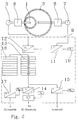
- FIG. 2 schematically shows the structure of the device for determining the total division error.
- Gear 1 and abrasive tool 3 are engaged again.
- Gear 1 is driven by the first drive element 6, abrasive tool 3 by the second drive element 8.
- Gear 1 is connected to the first pulse generator 5, abrasive tool 3 to the second pulse generator 7.
- the machine control 9 includes, among other things, a value memory for the value P m (see below), a first and second internal computing unit 11 and 12, a first and second storage means 13 and 16, a D / A converter 14 and the comparators 15 and 17.
- the procedure is as follows: The abrasive tool 3 is rotated by means of the second drive element 8. Gear 1 rotates without load, but in positive contact with tool 3.
- the value P m is predetermined in a value memory 10 of the machine control 9; it specifies the number of measuring points which - evenly distributed over the circumference - are to be queried on gear 1.
- the second internal computing unit 12 counts until it receives this signal from the first unit 11, the pulses coming from the first pulse generator 5. This value is then stored in the first storage means 13 of the machine control 9, specifically in the first position of the storage 13. This process is repeated until the gear 1 has been rotated (at least) by one complete revolution (360 °); the first storage means 13 is then assigned as many values as it corresponds to the number of measuring points P m , in the present schematic example thus 8 values. In the In practice it is necessary to choose several hundred points in order to obtain a sufficiently high accuracy.
- the content of the first storage means 13 is completed until it is in the form shown in FIG.
- the honing can then be carried out with feedforward control:
- the values from the memory 13 corresponding to the respective angular positions of the gear 1 are - with the opposite sign - applied when the movement of the tool and workpiece axis is rotationally coupled.
- the values from the storage means 13 are first converted from digital to analog in a D / A converter 14.
- V w gain factor
- a comparator 15 is provided for this purpose, which only triggers the machining of the gearwheel 1 when all the values contained in the memory 13 do not exceed a predetermined maximum error (F max ).
- a second storage means 16 is present, in which the above-described measurement of the sum division error during honing is repeated interactively or at defined intervals.
- a comparator 17 compares the values just determined with a predetermined minimum value (F min ) for the total division error and gives instructions for ending the honing process as soon as this value is undershot.
- the pulse values stored in the storage means (13, 16) are of course not yet the total division error. Rather, this only arises when the entire geometrical relationships of the tool, workpiece and device are taken into account and the determined pulse values have been processed by an appropriate algorithm.
- the operations described above can also be carried out without this conversion into the "real" sum division error, since the pulse sequences are proportional to the sum division error; the data for the specified minimum and maximum values (F min and F max ) must then of course be converted into corresponding "pulse units".
- the present invention naturally also includes the case in which it is not the explicitly calculated sum division error that is processed, but rather only the stored number of measured pulses.
Abstract
Description
Die Erfindung betrifft ein Vefahren für die Ermittlung des Summenteilungsfehlers eines Zahnrades in einer Werkzeugmaschine, insbesondere in einer Vezahnungs-Honmaschine, wobei sich das zu bearbeitende Zahnrad, das um seine Drehachse rotiert und sich mit einem Abrasivwerkzeug, das um seine Drehachse rotiert, im Eingriff befindet, wodurch es zum Spanabtrag an den zu bearbeitenden Zahnflanken des Zahnrads kommt, wobei die Drehachse des Zahnrades mit einem ersten Impulsgeber und einem ersten Antriebselement und die Drehachse des Abrasivwerkzeugs mit einem zweiten Impulsgeber und einem zweiten Antriebselement verbunden sind und wobei die Impulsgeber mit der Maschinensteuerung verbunden sind, die eine interne Recheneinheit, erste und zweite Speichermittel und eine Datenausgabeeinrichtung aufweist. Des weiteren betrifft die Erfindung eine Vorrichtung zur Durchführung dieses Verfahrens.The invention relates to a method for determining the total division error of a gear in a machine tool, in particular in a gear honing machine, wherein the gear to be machined which rotates about its axis of rotation and is in engagement with an abrasive tool which rotates about its axis of rotation , whereby there is chip removal on the tooth flanks of the gear to be machined, the axis of rotation of the gear being connected to a first pulse generator and a first drive element and the axis of rotation of the abrasive tool being connected to a second pulse generator and a second drive element, and wherein the pulse generators are connected to the machine control are, which has an internal computing unit, first and second storage means and a data output device. Furthermore, the invention relates to a device for performing this method.
Für die Hartbearbeitung von Zahnrädern sind verschiedene Fertigungsverfahren im Einsatz. Häufig werden wälzgefräste und gehärtete Zahnräder durch einen Schliefbearbeitungsvorgang mit der exakten Profilkontur (Evolvente) versehen. Manchmal wird dem Schleifbearbeitungsvorgang ein Zahnradhonvorgang nachgeschaltet, um noch nach dem Schleifen verbliebene Verzahnungsfehler zu minimieren. Im Hinblick auf einen ruhigen Lauf einer Verzahnung ist hierbei besonders der Summenteilungsfehler kritisch und zu beachten.Various manufacturing processes are used for the hard machining of gears. Gear milled and hardened gears are often given the exact profile contour (involute) through a machining process. A gear honing process is sometimes added to the grinding machining process in order to minimize any gear errors remaining after grinding. With regard to the smooth running of a toothing, the total division error is particularly critical and has to be taken into account.
Beim Zahnradhonen rotiert das zu bearbeitende Zahnrad um seine Drehachse. Dabei kämmt es mit einem Honwerkzeug, das - im Falle einer zu bearbeitenden Außenverzahnung - die Form eines innenverzahnten Ringes hat; das Honwerkzeug rotiert ebenfalls um seine Drehachse. Die Innenverzahnung des Honwerkzeugs entspricht dabei bei Berücksichtigung der Drehbewegung zwischen Werkzeug und Werkstück genau der Gegenkontur des zu bearbeitenden Profils. Um Materialabtrag vom hartzubearbeitenden Zahnrad zu bewerkstelligen, ist das Honwerkzeug mit Abrasivpartikeln versehen. Die Bearbeitung erfolgt indem beispielsweise das Werkstück angetrieben wird und das Werkzeug mit einem gewissen Schleppmoment nachläuft. Durch Änderung der Drehrichtung werden beide Zahnflanken (Schub und Zug) bearbeitet.With gear honing, the gear to be machined rotates about its axis of rotation. It combs with a honing tool that - in the case of one to be machined External teeth - has the shape of an internally toothed ring; the honing tool also rotates about its axis of rotation. The internal toothing of the honing tool corresponds exactly to the counter contour of the profile to be machined, taking into account the rotary movement between the tool and the workpiece. The honing tool is provided with abrasive particles in order to remove material from the hard-to-machine gear. The processing takes place, for example, by driving the workpiece and running the tool with a certain drag torque. By changing the direction of rotation, both tooth flanks (thrust and pull) are machined.
Hohe Anforderungen an die Qualität der zu bearbeitenden Zahnräder haben dazu geführt, daß leistungsfähige Hartbearbeitungsverfahren benötigt werden. Hinsichtlich des Zahnradhonens wurden Lösungen ins Auge gefaßt, bei denen die beiden Drehachsen von Werkzeug und Werkstück nicht mehr unabhängig voneinander arbeiten und nur durch das Schleppmoment des nicht angetriebenen Teils verbunden sind, sondern bei denen die beiden Drehachsen durch eine definierte Kopplung verbunden sind. Diese wird vorzugsweise unter Zuhilfenahme der NC-Technik elektronisch vorgenommen ("elektronische Welle").High demands on the quality of the gear wheels to be machined have resulted in the need for efficient hard machining processes. With regard to gear honing, solutions were envisaged in which the two axes of rotation of the tool and the workpiece no longer work independently of one another and are only connected by the drag torque of the non-driven part, but in which the two axes of rotation are connected by a defined coupling. This is preferably done electronically with the help of NC technology ("electronic wave").
Das Ziel dieser Maßnahme war, die Verzahnungsfehler durch den Honvorgang nicht nur "auszumitteln", also im Rahmen der Abwälzung mit dem - fehlerarmen - Honwerkzeug zu minimieren, sondern definiert durch Zwangskopplung der Drehachsen zu eliminieren.The aim of this measure was not only to "average out" the gear errors due to the honing process, that is, to minimize them as part of the rolling process with the - low-error - honing tool, but to eliminate them in a defined manner by forcibly coupling the axes of rotation.
Umfangreiche Versuche zeigten, daß mit den bekannten Honverfahren tatsächlich gewisse Vezahnungsfehler sehr klein gemacht werden können, namentlich der Rundlauffehler, der Flankenformfehler und der Einzelteilungsfehler der Verzahnung.Extensive tests showed that certain known toothing errors can actually be made very small with the known honing methods, namely the concentricity error, the flank shape error and the individual pitch error of the toothing.
Es zeigte sich aber auch, daß insbesondere der Summenteilungsfehler der Verzahnung auch bei Einsatz einer "elektronischen Welle" nach dem Honprozeß fast unverändert groß geblieben ist und in der Regel außerhalb der zulässigen Toleranzen liegt.However, it was also found that, in particular, the total division error of the toothing remained almost unchanged even when an "electronic shaft" was used after the honing process and was generally outside the permissible tolerances.
Jede hochgenaue Hartbearbeitung einer Verzahnung setzt daher die genaue Kenntnis des Summenteilungsfehlers voraus, so daß diesem gezielt begegnet werden kann. Hierfür bietet sich insbesondere an, den festgestellten Summenteilungsfehler "mit umgekehrten Vorzeichen" der Kopplung der Drehachsen von Werkzeug und Werkstück als Störgröße aufzuschalten (s. DE 43 17 306).Every highly precise hard machining of a toothing therefore requires precise knowledge of the total division error so that it is counteracted in a targeted manner can be. For this purpose, it is particularly advisable to apply the ascertained sum division error "with the opposite sign" to the coupling of the axes of rotation of the tool and the workpiece as a disturbance variable (see DE 43 17 306).
Da im Getriebebau in der Regel sehr große Lose Zahnräder gefertigt werden müssen, ist es daher erforderlich, eine Möglichkeit zu haben, mit der ohne großen (Zeit-)Aufwand in der Zahnradhonmaschine der effektiv vorliegende Summenteilungsfehler bestimmt werden kann.Since very large loose gears generally have to be manufactured in gear construction, it is therefore necessary to have a possibility with which the effective total division error can be determined in the gear honing machine without great (time) expenditure.
Der vorliegenden Erfindung liegt daher die Aufgabe zugrunde, ein Verfahren für die Ermittlung des Summenteilungsfehlers eines Zahnrades in einer Werkzeugmaschine, insbesondere in einer Verzahnungs-Honmaschine, zu schaffen, das in kurzer Zeit das Ergebnis liefert, um es sowohl für die weitere Bearbeitung ("Störgrößenaufschaltung") als auch für die Beurteilung des Werkstücks heranzuziehen.The present invention is therefore based on the object of providing a method for determining the total division error of a gearwheel in a machine tool, in particular in a gear honing machine, which delivers the result in a short time, so that it can be used both for further processing ("feedforward control ") as well as for the assessment of the workpiece.
Die Lösung der Aufgabe durch die Erfindung ist dadurch gekennzeichnet, daß der Summenteilungsfehler durch folgende durch die Maschinensteuerung gesteuerte Arbeitsschritte bestimmt wird:
- a) Drehung des Abrasivwerkzeugs (3) mittels des zweiten Antriebselements (8), so, daß das Zahnrad (1) mindestens eine volle Umdrehung (360 °) ausführt, wobei das Zahnrad (1) lastfrei, jedoch in formschlüssigem Kontakt mit dem Abrasivwerkzeug (3) mitläuft;
- b) Ausgabe je eines Signals von einer ersten internen Recheneinheit (11) der Maschinensteuerung (9) an eine zweite interne Recheneinheit (12), sobald ein definierter Drehweg des Abrasivwerkzeugs (3) stattgefunden hat, der einem vorher festgelegten Bruchteil der vollen Umdrehung (360 °) des Zahnrads (1) entspricht;
- c) Zählung der vom ersten Impulsgeber (5) während zweier aufeinanderfolgender Signale gemäß Arbeitsschritt b) abgegebenen Impulse in der zweiten internen Recheneinheit (12) und Abspeicherung in einem ersten Speichermittel (13) der Maschinensteuerung (9), solange, bis das Zahnrad (1) mindestens eine volle Umdrehung (360 °) ausgeführt hat;
- d) Errechnung des am Zahnrad (1) vorhandenen Summenteilungsfehlers durch Auswertung der im ersten Speichermittel (13) vorhandenen Werte unter Berücksichtigung der geometrischen Beziehungen zwischen Zahnrad (1), Abrasivwerkzeug (3) und Antriebsstrang durch die interne Recheneinheit der Maschinensteuerung (9).
- a) rotation of the abrasive tool (3) by means of the second drive element (8), so that the gear wheel (1) makes at least one full rotation (360 °), the gear wheel (1) being load-free but in positive contact with the abrasive tool ( 3) follows;
- b) output of a signal from a first internal processing unit (11) of the machine control (9) to a second internal processing unit (12) as soon as a defined rotation path of the abrasive tool (3) has taken place, which corresponds to a predetermined fraction of the full rotation (360 °) corresponds to the gear (1);
- c) counting the pulses emitted by the first pulse generator (5) during two successive signals in accordance with work step b) in the second internal arithmetic unit (12) and storing them in a first storage means (13) of the machine control (9) until the gearwheel (1 ) has made at least one full revolution (360 °);
- d) Calculation of the total division error on the gearwheel (1) by evaluating the values available in the first storage means (13), taking into account the geometric relationships between the gearwheel (1), the abrasive tool (3) and the drive train by the internal computer unit of the machine control (9).
Durch die erfindungsgemäßen Kennzeichen wird erreicht, daß mit verfügbaren Steuerungssystemen unter Zuhilfenahme der Impulsgeber der NC-Achsen der Werkzeugmaschine sehr schnell der vorliegende Summenteilungsfehler des Zahnrads (1) ermittelt werden kann. Natürlich ist die primäre Anwendung des Wissens um diesen Fehler, diesen Wert (als Funktionsverlauf über der Winkelkoordinate des Zahnrads) bei der Honbearbeitung zugrunde zulegen; wie oben bereits skizziert, wird der Fehler als Störgröße der "elektronischen Welle" aufgeschaltet.The characteristics of the invention ensure that the available totalization error of the gearwheel (1) can be determined very quickly with available control systems with the aid of the pulse generators of the NC axes of the machine tool. Of course, the primary application of knowledge about this error is to base this value (as a function over the angular coordinate of the gear) in honing; As already outlined above, the error is applied as a disturbance variable of the "electronic wave".
Gemäß eines weiteren Kennzeichens der Erfindung werden also die im ersten Speichermittel (13) der Maschinensteuerung (9) abgelegten Werte, gegebenenfalls nach einer Digital-Analogwandlung, als Störgröße bei der Bearbeitung des Zahnrads (1) mit dem Abrasivwerkzeug (3) aufgeschaltet, wobei dann die Drehachse (2) des Zahnrads (1) und die Drehachse (4) des Abrasivwerkzeugs (3) elektronisch gekoppelt sind.According to a further feature of the invention, the values stored in the first storage means (13) of the machine control (9), if necessary after a digital-to-analog conversion, are applied as a disturbance variable when the gearwheel (1) is machined with the abrasive tool (3) the axis of rotation (2) of the gear wheel (1) and the axis of rotation (4) of the abrasive tool (3) are electronically coupled.
Da stets gewisse Elastizitäten, d. h. nur begrenzte Steifigkeiten der einzelnen Elemente, in den Antrieben und Maschinenelementen vorhanden sind, kann es sinnvoll sein, die Störgröße, die der Kopplung der Drehachsen von Zahnrad (1) und Abrasivwerkzeug (3) aufgeschaltet wird, mit einem Verstärkungsfaktor zu multiplizieren, um eine effizientere, also kürzere Bearbeitung zu erreichen.Because there are always certain elasticities, i.e. H. With only limited stiffnesses of the individual elements in the drives and machine elements, it can make sense to multiply the disturbance variable that is applied to the coupling of the axes of rotation of the gear wheel (1) and the abrasive tool (3) by a gain factor in order to achieve a more efficient one to achieve shorter processing times.
Da mitunter schlecht vorgearbeitete oder stark härteverzogene Zahnräder an die Hartfeinbearbeitungsmaschine gelangen, die das Abrasivwerkzeug (3) über Gebühr strapazieren, ist die Erfindung vorteilhafterweise derart weitergebildet, daß die Maschinensteuerung (9) nach Ermittlung des Summenteilungsfehlers keine Bearbeitung des Zahnrads (1) mit dem Abrasivwerkzeug (3) einleitet, wenn der Summenteilungsfehler einen vorgegebenen Maximalwert übersteigt. Hierdurch kann das Werkzeug (3) erheblich geschont werden.Since sometimes poorly prepared or heavily warped gear wheels get to the hard fine machining machine, which unduly stress the abrasive tool (3), the invention is advantageously further developed such that the machine control (9) does not process the gear wheel (1) with the abrasive tool after determining the total division error (3) initiates when the sum division error exceeds a predetermined maximum value. As a result, the tool (3) can be spared considerably.
Um den Arbeitsfortschritt während des Zahnradhonens zu beobachten und zu gegebener Zeit den Bearbeitungsprozeß zu beenden, ist vorgesehen, daß die Ermittlung des Summenteilungsfehlers während der Bearbeitung des Zahnrads (1) mit dem Abrasivwerkzeug (3) in vorgebbaren Zeitabständen oder kontinuierlich wiederholt wird, wobei die Abspeicherung gemäß obigem Arbeitsschritt c) in einem zweiten Speichermittel (16) der Maschinensteuerung (9) erfolgt.In order to observe the progress of work during gear honing and to end the machining process at the appropriate time, it is provided that the determination of the total division error during machining of the gear (1) with the abrasive tool (3) is repeated at predefinable time intervals or continuously, with the storage in a second storage means (16) of the machine control (9) in accordance with step c) above.
Dann kann der ermittelte Wert des Summenteilungsfehlers an der Datenausgabeeinrichtung der Maschinensteuerung (9) gleichzeitig mit seiner Ermittlung angezeigt werden. Außerdem kann vorgesehen werden, daß die Maschinensteuerung (9) die Bearbeitung des Zahnrads (1) mit dem Abrasivwerkzeug (3) beendet, sobald der ermittelte Wert des Summenteilungsfehlers einen vorgegebenen Minimalwert unterschreitet.Then the determined value of the total division error can be displayed on the data output device of the machine control (9) at the same time as it is determined. In addition, it can be provided that the machine control (9) ends the machining of the gearwheel (1) with the abrasive tool (3) as soon as the determined value of the total division error falls below a predetermined minimum value.
Alle obigen Ausführungen gelten natürlich auch dann, wenn bei der Durchführung des obigen Arbeitsschrittes a) das Zahnrad (1) mittels des ersten Antriebselements (7) gedreht wird und das Abrasivwerkzeug (3) lastfrei, jedoch in formschlüssigem Kontakt mit dem Zahnrad (1) mitläuft.All of the above explanations also apply, of course, when the gear (1) is rotated by means of the first drive element (7) and the abrasive tool (3) rotates without load but in positive contact with the gear (1) when carrying out the above step a) .
In der Zeichnung ist ein Ausführungsbeispiel dargestellt, an dem das erfindungsgemäße Verfahren erläutert werden soll. Es zeigt
- Fig. 1:
- Werkstück und Werkzeug im Eingriff während des Bearbeitungsprozesses,
- Fig. 2:
- Schema des Vorrichtungsaufbaus für die Ermittlung des Summenteilungsfehlers und
- Fig. 3:
- den Verlauf der über dem Drehwinkel von den beiden Impulsgebern eingehenden Signale.
- Fig. 1:
- Workpiece and tool in engagement during the machining process,
- Fig. 2:
- Scheme of the device structure for the determination of the sum division error and
- Fig. 3:
- the course of the signals coming in from the two pulse generators over the angle of rotation.
In Figur 1 ist das zu bearbeitende Zahnrad 1 zu erkennen. Es weist eine Drehachse 2 auf, um die es während des Honbearbeitsprozesses dreht (Drehrichtung A). Das Zahnrad 1 kämmt mit dem Abrasivwerkzeug 3, welches um seine Drehachse 4 drehen kann (Drehrichtung B). Dargestellt ist der - einfachste - Fall der Bearbeitung eines Stirnzahnrades mit parallel zur Drehachse 2 verlaufenen Zähnen (Geradvezahnung). Die erfindungsgemäßen Ausführungen gelten jedoch genauso für Schrägverzahnungen und für zu bearbeitende Innenverzahnungen. Dann hat freilich das Werkzeug die Form eines außenverzahnten Stirnrades (in Figur 1 würde dann Nr. 1 das Werkzeug und Nr. 3 das Werkstück sein).The
Das Abrasivwerkzeug (Honrad) 3 beinhaltet die Gegenkontur des Werkstücks 1; beim Abwälzen von Werkzeug 3 und Werkstück 1 erzeugt das Werkzeug 3 am Werkstück 1 exakt die gewünschte Profilform. Materialabtrag (Abrasion) findet dadurch statt, daß die Kontaktfläche zwischen Werkstück und Werkzeug werkzeugseitig mit Abrasivmaterial versehen ist. Zum Einsatz kann ein Werkzeug kommen, das ganz aus abrichtbarem Schleifmittel besteht und in das, z. B. mittels eines diamantbesetzten Lehrenzahnrades, die gewünschte Profilform eingebracht wurde. Das Werkzeug kann aber auch aus einem metallischen Grundkörper bestehen, der bereits exakt auf eine äquidistant kleinere Form gefertigt wurde und mit einer einlagigen Schicht aus superhartem Material besteht (z. B. CBN), mit der sich dann die exakte benötigte Werkzeugform ergibt.The abrasive tool (honing wheel) 3 contains the counter contour of the
Nicht dargestellt sind in Figur 1 der Impulsgeber 5, der mit der Drehachse 2 des Zahnrads 1 verbunden ist und das erste Antriebselement 6, das das Zahnrad 1 antreibt; gleichermaßen nicht dargestellt sind der Impulsgeber 7, der mit der Drehachse 4 des Abrasivwerkzeugs 3 verbunden ist und das zweite Antriebselement 8, das das Abrasivwerkzeug 3 antreibt.Not shown in Figure 1 are the
Die Drehbewegung der Achsen 2 und 4 (Drehrichtungen A und B) ist elektronisch gekoppelt ("elektronische Welle"); d. h. zu jeder Winkelposition der Werkstückwelle gehört eine zugehörige Winkelposition der Werkzeugwelle, die regelungstechnisch exakt zugeordnet und positioniert wird.The rotation of
In Figur 2 ist schematisch der Vorrichtungsaufbau für die Ermittlung des Summenteilungsfehlers dargestellt Zahnrad 1 und Abrasivwerkzeug 3 befinden sich wieder im Eingriff. Zahnrad 1 wird vom ersten Antriebselement 6, Abrasivwerkzeug 3 vom zweiten Antriebselement 8 angetrieben. Zahnrad 1 ist mit dem ersten Impulsgeber 5, Abrasivwerkzeug 3 mit dem zweiten Impulsgeber 7 verbunden.FIG. 2 schematically shows the structure of the device for determining the total division error.
Die Maschinensteuerung 9 beinhaltet unter anderem einen Wertspeicher für den Wert Pm (s. u.), eine erste und zweite interne Recheneinheit 11 und 12, ein erstes und zweites Speichermittel 13 und 16, einen D/A-Wandler 14 sowie die Komparatoren 15 und 17.The
Die erfindungsgemäßen Überlegungen gehen davon aus, daß das Abrasivwerkzeug 3 weitgehend fehlerfrei ist, während das zu bearbeitende Zahnrad 1 gewisse Summenteilungsfehler aufweist. Diese Annahme entspricht der Praxis, da Werkzeuge für die Zahnrad-Hartfeinbearbeitung stets in sehr hoher Qualität gefertigt werden, so daß deren - stets vorhandene -Fehler vernachlässigbar sind, verglichen mit denjenigen des Werkstücks.The considerations according to the invention assume that the
Zwecks Ermittlung des Summenteilungsfehlers des Zahnrads 1 wird folgendermaßen vorgegangen:
Das Abrasivwerkzeug 3 wird mittels des zweiten Antriebselements 8 gedreht. Zahnrad 1 dreht sich lastfrei, jedoch in formschlüsigem Kontakt mit dem Werkzeug 3 mit. In einen Wertspeicher 10 der Maschinensteuerung 9 ist der Wert Pm vorgegeben; er gibt die Anzahl der Meßpunkte an, die - gleichmäßig über den Umfang verteilt - am Zahnrad 1 abgefragt werden sollen. Eine erste interne Recheneinheit 11, die die Anzahl der Meßpunkte und die Impulse des zweiten Impulsgebers 7 vorgegeben bekommt, berechnet unter Berücksichtigung des Zähnezahlverhältnisses von Zahnrad 1 und Abrasivwerkzeug 3 und von gegebenenfalls in den Antriebselementen vorhandenen Übersetzungen die Anzahl der Impulse, die vom zweiten Impulsgeber 7 abgegeben worden sein müssen, bis sich das Zahnrad 1 um den ersten Teilwinkel (2 Pi / Pm) gedreht hat. Dann gibt sie ein Signal an eine zweite interne Recheneinheit 12 ab ("Zeitpunkt der Aufnahme eines Meßpunkts").In order to determine the total division error of
The
Die zweite interne Recheneinheit 12 zählt solange, bis sie von der ersten Einheit 11 dieses Signal erhählt, die vom ersten Impulsgeber 5 eingehenden Impulse. Dieser Wert wird dann in das erste Speichermittel 13 der Maschinensteuerung 9 abgespeichert, und zwar an die erste Stelle des Speichers 13. Dieser Vorgang wiederholt sich solange, bis das Zahnrad 1 (mindestens) um eine vollständige Umdrehung (360 °) gedreht wurde; das erste Speichermittel 13 ist dann mit sovielen Werten belegt, wie es der Anzahl der Meßpunkte Pm entspricht, im vorliegenden schematischen Beispiel also mit 8 Werten. In der Praxis ist es erforderlich, mehrere Hundert Punkte zu wählen, um eine genügend hohe Genauigkeit zu erhalten.The second
In Figur 3 ist der Verlauf der von den beiden Impulsgebern 5 und 7 eingehenden Signale über dem Drehwinkel (Phi 1) des Zahnrads 1 schematisch dargestellt. Als einfaches Beispiel wurden hier wieder die mit Figur 2 korrespondierenden 8 Werte zugrundegelegt. Während des ersten Achtels der Zahnradumdrehung - berechnet ausgehend vom exakten, "idealen" Abrasivwerkzeug- zählt der zweite Impulsgeber 7 im vorliegenden Beispiel 100 Impulse (bis zum Drehwinkel Pi/4). Dann erfolgt das Signal von der ersten internen Recheneinheit 11 an die zweite Einheit 12 (Piek nach Pi/4). Bis zu diesem Zeitpunkt gingen vom ersten Impulsgeber 5 102 Impulse ein (s. Figur 3), so daß also ein Summenteilungsfehler vorliegt; dies wäre nur dann nicht der Fall, wenn vom ersten Impulsgeber ebenfalls 100 Impulse eingegangen wären.In Figure 3, the course of the incoming signals from the two
Durch weiteres "Vermessen" des Zahnrads 1 über seinen Umfang vervollständigt sich der Inhalt des ersten Speichermittels 13, bis er in der in Figur 2 dargestellten Form vorliegt. Anschließend kann die Honbearbeitung mit Störgrößenaufschaltung vorgenommen werden: Die zu den jeweiligen Winkellagen des Zahnrads 1 korrespondierenden Werte aus dem Speicher 13 werden - mit umgekehrten Vorzeichen - bei der Drehkopplung der Bewegung von Werkzeug- und Werkstückachse aufgeschaltet. Hierfür werden die Werte aus dem Speichermittel 13 zunächst in einem D/A-Wandler 14 von digitaler Form in analoge umgewandelt. Zur Erhöhung der Effizienz des Bearbeitungsvorgang ist es angebracht, die vom D/A-Wandler an die NC-Steuerung ausgegebenen Daten mit einem Verstärkungsfaktor Vw zu multiplizieren, der z. B. 1,2 betragen kann.By further "measuring" the
Nach Aufnahme aller Werte in das Speichermittel 13 kann es sinnvoll sein, die dann vorhandenden Werte zunächst vor der eigentlichen Bearbeitung daraufhin zu überprüfen, ob der vorhandene Summenteilungsfehler nicht so groß ist, daß sich eine Bearbeitung nicht lohnt (Ausschuß). Hierfür ist ein Komparator 15 vorhanden, der die Bearbeitung des Zahnrads 1 erst veranlaßt, wenn alle im Speicher 13 enthaltenen Werte einen vorgegebenen Maximalfehler (Fmax) nicht überschreiten.After all the values have been stored in the storage means 13, it may be useful to first check the then existing values before the actual processing to determine whether the existing total division error is not so great that processing is not worthwhile (reject). A
Um den Arbeitsfortschritt während des Honens zu überprüfen und schließlich auch die Bearbeitung zu beenden, ist ein zweites Speichermittel 16 vorhanden, in dem oben beschriebene Messung des Summenteilungsfehlers während des Honens interaktiv in definierten Zeitabständen oder kontinuierlich wiederholt wird. Ein Komparator 17 vergleicht die soeben ermittelten Werte mit einem vorgegebenen Minimalwert (Fmin) für den Summenteilungsfehler und gibt Anweisung für die Beendigung der Honbearbeitung, sobald dieser Wert unterschritten ist.In order to check the work progress during honing and finally also to finish the processing, a second storage means 16 is present, in which the above-described measurement of the sum division error during honing is repeated interactively or at defined intervals. A
Es ist am Rande anzumerken, daß die im Speichermittel (13, 16) abgelegten Impulswerte natürlich noch nicht der Summenteilungsfehler sind. Dieser ergibt sich vielmehr erst dann, wenn die gesamten geometrischen Verhältnisse von Werkzeug, Werkstück und Vorrichtung berücksichtigt werden und die ermittelten Impulswerte durch einen entsprechenden Algorithmus verarbeitet worden sind. Die oben beschriebenen Operationen können jedoch auch ohne diese Umrechnung in den "echten" Summenteilungsfehler vorgenommen werden, da die Impulsfolgen propotional zum Summenteilungsfehler sind; die Daten für die vorgegebenen Minimal- und Maximalwerte (Fmin und Fmax) sind dann natürlich in entsprechende "Impulseinheiten" umzurechnen. Vorliegende Erfindung schließt insofern natürlich auch den Fall ein, daß nicht explizit berechnete Summenteilungsfehler, sondern lediglich die gespeicherte Anzahl gemessener Impulse verarbeitet wird.It should be noted in passing that the pulse values stored in the storage means (13, 16) are of course not yet the total division error. Rather, this only arises when the entire geometrical relationships of the tool, workpiece and device are taken into account and the determined pulse values have been processed by an appropriate algorithm. However, the operations described above can also be carried out without this conversion into the "real" sum division error, since the pulse sequences are proportional to the sum division error; the data for the specified minimum and maximum values (F min and F max ) must then of course be converted into corresponding "pulse units". In this respect, the present invention naturally also includes the case in which it is not the explicitly calculated sum division error that is processed, but rather only the stored number of measured pulses.
Weiterhin ist zu sagen, daß die gesamte schaltungstechnische Ausführungsform in praxi noch ergänzt werden muß mit üblichen Synchronisationsvorrichtungen hinsichtlich des Starts einer Impulsfolge (ein Referenztakt muß vorgegeben werden). Derartige Techniken stellen jedoch den Stand der Technik dar, auf den die vorliegende Erfindung zurückgreift.Furthermore, it must be said that the entire circuitry embodiment in practice still has to be supplemented with conventional synchronization devices with regard to the start of a pulse train (a reference clock must be specified). However, such techniques represent the state of the art to which the present invention relies.
- 11
- Zahnradgear
- 22nd
- Drehachse des ZahnradesAxis of rotation of the gear
- 33rd
- AbrasivwerkzeugAbrasive tool
- 44th
- Drehachse des AbrasivwerkzeugsAxis of rotation of the abrasive tool
- 55
- erster Impulsgeberfirst pulse generator
- 66
- erstes Antriebselementfirst drive element
- 77
- zweiter Impulsgebersecond pulse generator
- 88th
- zweites Antriebselementsecond drive element
- 99
- MaschinensteuerungMachine control
- 1010th
- Wertspeicher der Maschinensteuerung für Pm Machine control value memory for P m
- 1111
- erste interne Recheneinheitfirst internal processing unit
- 1212th
- zweite interne Recheneinheitsecond internal processing unit
- 1313
- erstes Speichermittelfirst storage medium
- 1414
- D/A-WandlerD / A converter
- 1515
- KomparatorComparator
- 1616
- zweites Speichermittelsecond storage means
- 1717th
- KomparatorComparator
- AA
- Drehrichtung des ZahnradesDirection of rotation of the gear
- BB
- Drehrichtung des AbrasivwerkzeugsDirection of rotation of the abrasive tool
- Pm P m
- Anzahl der Meßpunkte über den Umfang des ZahnradsNumber of measuring points over the circumference of the gear
- Vw V w
- VerstärkungsfaktorGain factor
- Fmin F min
- Minimalwert für SummenteilungsfehlerMinimum value for total division errors
- Fmax F max
- Maximalwert für SummenteilungsfehlerMaximum value for total division errors
- I₅I₅
- Impulse des ersten ImpulsgebersFirst pulse generator
- I₇I₇
- Impulse des zweiten ImpulsgebersPulses from the second encoder
Claims (9)
wobei die Drehachse (2) des Zahnrades (1) mit einem ersten Impulsgeber (5) und einem ersten Antriebselement (6) und die Drehachse (4) des Abrasivwerkzeugs (3) mit einem zweiten Impulsgeber (7) und einem zweiten Antriebselement (8) verbunden sind
und wobei die Impulsgeber (5, 7) mit der Maschinensteuerung (9) verbunden sind, die eine interne Recheneinheit, erste und zweite Speichermittel und eine Datenausgabeeinrichtung aufweist,
dadurch gekennzeichnet,
daß der Summenteilungsfehler durch folgende durch die Maschinensteuerung gesteuerte Arbeitsschritte bestimmt wird:
the axis of rotation (2) of the gearwheel (1) having a first pulse generator (5) and a first drive element (6) and the axis of rotation (4) of the abrasive tool (3) having a second pulse generator (7) and a second drive element (8) are connected
and wherein the pulse generators (5, 7) are connected to the machine control (9), which has an internal computing unit, first and second storage means and a data output device,
characterized,
that the total division error is determined by the following work steps controlled by the machine control:
Applications Claiming Priority (2)
| Application Number | Priority Date | Filing Date | Title |
|---|---|---|---|
| DE4321448A DE4321448C2 (en) | 1993-06-29 | 1993-06-29 | Method for determining the total division error of a gear to be machined |
| DE4321448 | 1993-06-29 |
Publications (1)
| Publication Number | Publication Date |
|---|---|
| EP0632249A1 true EP0632249A1 (en) | 1995-01-04 |
Family
ID=6491407
Family Applications (1)
| Application Number | Title | Priority Date | Filing Date |
|---|---|---|---|
| EP94109594A Withdrawn EP0632249A1 (en) | 1993-06-29 | 1994-06-22 | Method and apparatus for determining cumulative pitch error of a gearwheel |
Country Status (8)
| Country | Link |
|---|---|
| EP (1) | EP0632249A1 (en) |
| JP (1) | JPH07314249A (en) |
| KR (1) | KR950001276A (en) |
| CN (1) | CN1102880A (en) |
| BR (1) | BR9402569A (en) |
| CA (1) | CA2126820A1 (en) |
| CZ (1) | CZ134794A3 (en) |
| DE (1) | DE4321448C2 (en) |
Cited By (1)
| Publication number | Priority date | Publication date | Assignee | Title |
|---|---|---|---|---|
| EP2072166A1 (en) * | 2006-10-31 | 2009-06-24 | Mitsubishi Heavy Industries, Ltd. | Method and device for detecting tooth matching angle of gear |
Families Citing this family (12)
| Publication number | Priority date | Publication date | Assignee | Title |
|---|---|---|---|---|
| ES2286184T3 (en) * | 2002-08-30 | 2007-12-01 | Siemens Aktiengesellschaft | EVALUATION PROCEDURE OF THE OPERATING CONDITIONS OF A MACHINE OR AN INSTALLATION. |
| CN100450710C (en) | 2007-01-15 | 2009-01-14 | 大连光洋科技工程有限公司 | Manual impulsator with indicating lamp |
| DE112007003259B4 (en) * | 2007-01-15 | 2012-01-05 | Dalian Guangyang Science & Technology Engineering Co., Ltd. | Manually adjustable pulse generator with integrated indicator lights by hand or pushbutton |
| CN101637835B (en) * | 2009-09-04 | 2011-07-20 | 宝钢集团苏州冶金机械厂 | Method for machining and detecting helical gear with key way |
| CN101920479A (en) * | 2010-04-13 | 2010-12-22 | 宁波超能液压有限公司 | Dividing device for honing machine |
| DE102011082868B4 (en) | 2011-09-16 | 2015-10-29 | Felsomat Gmbh & Co. Kg | Honing process with the introduction of a workpiece at a Wälzprüfstation and honing machine for performing the method |
| FR3002038B1 (en) * | 2013-02-13 | 2015-03-20 | Hispano Suiza Sa | DEVICE FOR THE MECHANICAL TESTING OF A GEAR BETWEEN AN INTERNAL TOOTH AND EXTERNAL TOOTHING AND / OR BETWEEN TWO EXTERIOR DENTURES ACCORDING TO AN ADJUSTABLE ANGLE |
| CN107876905B (en) * | 2017-11-27 | 2019-05-07 | 重庆大学 | A kind of worm abrasion wheel roll flute error compensating method based on imaginary axis |
| JP6856598B2 (en) * | 2018-10-02 | 2021-04-07 | ファナック株式会社 | Gear processing machine control device |
| JP6781228B2 (en) * | 2018-10-02 | 2020-11-04 | ファナック株式会社 | Disturbance component identification method and disturbance component identification device |
| DE102020007110A1 (en) | 2020-11-20 | 2022-05-25 | Gleason Switzerland Ag | Method for machining gears and tool designed for this purpose |
| CN112857794B (en) * | 2021-03-11 | 2023-04-14 | 苏州普瑞川传动科技有限公司 | Quick detection device of gear error |
Citations (8)
| Publication number | Priority date | Publication date | Assignee | Title |
|---|---|---|---|---|
| DE2334772A1 (en) * | 1973-07-09 | 1975-01-30 | Siemens Ag | Testing appts. for gearwheels - uses device which brings in mesh two gears designed to operate together, and has two shafts |
| DE2412574A1 (en) * | 1974-03-15 | 1975-09-25 | Maag Zahnraeder & Maschinen Ag | ELECTRONIC PITCH MEASURING DEVICE FOR GEARS |
| DE2627729A1 (en) * | 1975-09-29 | 1977-04-07 | Jenoptik Jena Gmbh | Toothed wheel meshing fault detection device - has third carriage carrying specimen gear meshing with second gear to generate electrical signal |
| SU920363A1 (en) * | 1980-07-25 | 1982-04-15 | Институт Машиноведения Им. Академика А.А.Благонравова | Toothed gear checking method |
| US4488359A (en) * | 1983-01-12 | 1984-12-18 | Lear Siegler, Inc. | Automatic gear checking structure and method |
| US4704799A (en) * | 1986-09-25 | 1987-11-10 | Illinois Tool Works Inc. | Master gear error compensation |
| JPH04336915A (en) * | 1991-05-09 | 1992-11-25 | Nachi Fujikoshi Corp | Tooth alignment method for nc device |
| DE4317306A1 (en) * | 1993-05-26 | 1993-10-28 | Kapp Werkzeugmasch | Honing process and machine for finishing gear teeth - has abrasive gear hone in mesh with workpiece gear and electronically coupled spindles so that pitch errors in gear can be measured and corrected by modifying relative speeds |
Family Cites Families (1)
| Publication number | Priority date | Publication date | Assignee | Title |
|---|---|---|---|---|
| DE3730249A1 (en) * | 1987-09-09 | 1989-04-06 | Karlheinz Bumm | Method and device for lapping bevel gears |
-
1993
- 1993-06-29 DE DE4321448A patent/DE4321448C2/en not_active Expired - Fee Related
-
1994
- 1994-06-01 CZ CZ941347A patent/CZ134794A3/en unknown
- 1994-06-22 EP EP94109594A patent/EP0632249A1/en not_active Withdrawn
- 1994-06-24 JP JP6176220A patent/JPH07314249A/en active Pending
- 1994-06-27 CA CA002126820A patent/CA2126820A1/en not_active Abandoned
- 1994-06-27 KR KR1019940014804A patent/KR950001276A/en not_active Application Discontinuation
- 1994-06-28 BR BR9402569A patent/BR9402569A/en unknown
- 1994-06-29 CN CN94107834A patent/CN1102880A/en active Pending
Patent Citations (8)
| Publication number | Priority date | Publication date | Assignee | Title |
|---|---|---|---|---|
| DE2334772A1 (en) * | 1973-07-09 | 1975-01-30 | Siemens Ag | Testing appts. for gearwheels - uses device which brings in mesh two gears designed to operate together, and has two shafts |
| DE2412574A1 (en) * | 1974-03-15 | 1975-09-25 | Maag Zahnraeder & Maschinen Ag | ELECTRONIC PITCH MEASURING DEVICE FOR GEARS |
| DE2627729A1 (en) * | 1975-09-29 | 1977-04-07 | Jenoptik Jena Gmbh | Toothed wheel meshing fault detection device - has third carriage carrying specimen gear meshing with second gear to generate electrical signal |
| SU920363A1 (en) * | 1980-07-25 | 1982-04-15 | Институт Машиноведения Им. Академика А.А.Благонравова | Toothed gear checking method |
| US4488359A (en) * | 1983-01-12 | 1984-12-18 | Lear Siegler, Inc. | Automatic gear checking structure and method |
| US4704799A (en) * | 1986-09-25 | 1987-11-10 | Illinois Tool Works Inc. | Master gear error compensation |
| JPH04336915A (en) * | 1991-05-09 | 1992-11-25 | Nachi Fujikoshi Corp | Tooth alignment method for nc device |
| DE4317306A1 (en) * | 1993-05-26 | 1993-10-28 | Kapp Werkzeugmasch | Honing process and machine for finishing gear teeth - has abrasive gear hone in mesh with workpiece gear and electronically coupled spindles so that pitch errors in gear can be measured and corrected by modifying relative speeds |
Non-Patent Citations (2)
| Title |
|---|
| DATABASE WPI Week 8307, Derwent World Patents Index; AN 83-C3957K * |
| PATENT ABSTRACTS OF JAPAN vol. 17, no. 181 (M - 1394) 8 April 1993 (1993-04-08) * |
Cited By (2)
| Publication number | Priority date | Publication date | Assignee | Title |
|---|---|---|---|---|
| EP2072166A1 (en) * | 2006-10-31 | 2009-06-24 | Mitsubishi Heavy Industries, Ltd. | Method and device for detecting tooth matching angle of gear |
| EP2072166A4 (en) * | 2006-10-31 | 2014-02-19 | Mitsubishi Heavy Ind Ltd | Method and device for detecting tooth matching angle of gear |
Also Published As
| Publication number | Publication date |
|---|---|
| DE4321448C2 (en) | 1995-08-31 |
| DE4321448A1 (en) | 1995-01-12 |
| CZ134794A3 (en) | 1997-08-13 |
| CN1102880A (en) | 1995-05-24 |
| KR950001276A (en) | 1995-01-03 |
| CA2126820A1 (en) | 1994-12-30 |
| JPH07314249A (en) | 1995-12-05 |
| BR9402569A (en) | 1995-03-14 |
Similar Documents
| Publication | Publication Date | Title |
|---|---|---|
| DE3134147C2 (en) | ||
| DE4317306C2 (en) | Process for finishing the tooth flanks of gears | |
| DE3150961C2 (en) | Method and device for machining a gear by means of a rotating, gear-like tool | |
| EP0632249A1 (en) | Method and apparatus for determining cumulative pitch error of a gearwheel | |
| EP3556501A1 (en) | Method for grinding a cogged workpiece and grinding machine with a controller for grinding a cogged workpiece | |
| CH678291A5 (en) | ||
| EP1084786B1 (en) | Method of dressing an internally or externally toothed tool for finishing gear flanks | |
| WO1987000782A1 (en) | Process for sparkerosion or electrochemical machining of tapered gears with hypoid tooth profile or similar parts | |
| EP0174280B1 (en) | Gear tooth, method and machine therefor | |
| EP3584025A1 (en) | Method for topological grinding of a cogged workpiece and grinding machine with a controller for topological grinding of a cogged workpiece | |
| EP0140831B1 (en) | Method and apparatus for eliminating the waviness of tooth flanks at gear manufacturing machines | |
| DE3519132C2 (en) | ||
| CH684827A5 (en) | Method and apparatus for lapping the teeth of a pair of gears. | |
| EP4066974A1 (en) | Method for creating constraints on the tooth flanks of an internally cogged workpiece | |
| EP0491067B1 (en) | Slip limiting process | |
| DE102018126259A1 (en) | Process for dressing a grinding worm and device for dressing a grinding worm | |
| DE102020106910A1 (en) | Process for generating a gear | |
| DE3314793A1 (en) | Method and device for automatically regulating the angular position of a rough-toothed workpiece relative to a worm-shaped tool | |
| DE2644331C3 (en) | Device for manufacturing or machining spur gears | |
| DE3402429A1 (en) | Device for the automatic positioning of a tooth-milling cutter or groove-milling cutter with respect to an already existing tooth system or groove system | |
| DE3730249A1 (en) | Method and device for lapping bevel gears | |
| DE4413229A1 (en) | Method and apparatus for the finish machining of gears | |
| DE3501935C1 (en) | Method of fine-machining the flanks of gears with a gear-like tool coated with grains of mechanically resistant material | |
| WO2022101038A1 (en) | Method for dressing a multi-flight worm grinding wheel for grinding teeth or similar profiles | |
| DE3617912A1 (en) | Method for driving a workpiece carrier or tool carrier without play and drive for carrying out this method |
Legal Events
| Date | Code | Title | Description |
|---|---|---|---|
| PUAI | Public reference made under article 153(3) epc to a published international application that has entered the european phase |
Free format text: ORIGINAL CODE: 0009012 |
|
| AK | Designated contracting states |
Kind code of ref document: A1 Designated state(s): AT BE CH DK ES FR GB GR IT LI NL PT SE |
|
| STAA | Information on the status of an ep patent application or granted ep patent |
Free format text: STATUS: THE APPLICATION IS DEEMED TO BE WITHDRAWN |
|
| 18D | Application deemed to be withdrawn |
Effective date: 19950606 |