EP0630816B1 - Method for batching granular and similar articles and a device for carrying out such method - Google Patents
Method for batching granular and similar articles and a device for carrying out such method Download PDFInfo
- Publication number
- EP0630816B1 EP0630816B1 EP94830312A EP94830312A EP0630816B1 EP 0630816 B1 EP0630816 B1 EP 0630816B1 EP 94830312 A EP94830312 A EP 94830312A EP 94830312 A EP94830312 A EP 94830312A EP 0630816 B1 EP0630816 B1 EP 0630816B1
- Authority
- EP
- European Patent Office
- Prior art keywords
- batching
- cask
- articles
- casks
- designed
- Prior art date
- Legal status (The legal status is an assumption and is not a legal conclusion. Google has not performed a legal analysis and makes no representation as to the accuracy of the status listed.)
- Expired - Lifetime
Links
- 238000000034 method Methods 0.000 title claims description 11
- 230000002269 spontaneous effect Effects 0.000 claims description 4
- 230000002093 peripheral effect Effects 0.000 description 2
- 238000010276 construction Methods 0.000 description 1
- 230000001419 dependent effect Effects 0.000 description 1
- 238000006073 displacement reaction Methods 0.000 description 1
- 230000005484 gravity Effects 0.000 description 1
- 238000004519 manufacturing process Methods 0.000 description 1
- 238000007790 scraping Methods 0.000 description 1
- 239000000126 substance Substances 0.000 description 1
- 230000032258 transport Effects 0.000 description 1
Images

Classifications
-
- B—PERFORMING OPERATIONS; TRANSPORTING
- B65—CONVEYING; PACKING; STORING; HANDLING THIN OR FILAMENTARY MATERIAL
- B65B—MACHINES, APPARATUS OR DEVICES FOR, OR METHODS OF, PACKAGING ARTICLES OR MATERIALS; UNPACKING
- B65B37/00—Supplying or feeding fluent-solid, plastic, or liquid material, or loose masses of small articles, to be packaged
- B65B37/16—Separating measured quantities from supply
- B65B37/20—Separating measured quantities from supply by volume measurement
Definitions
- the present invention lies in the technical field concerning batching granular and similar articles, in particular delicate and easily perishable articles.
- batching devices that fill bottles or other containers with a prefixed quantity of a product, e.g. granular, powdered or similar substances.
- Such devices usually have a rotating carousel equipped peripherally with a plurality of batching casks, distributed regularly, in contact with a space or an angular channel that is fed with the product to be put in the bottles.
- the lower parts of the casks are closed by a shutter that can be opened, in a special operative station, in order to unload the product into a hopper aimed at filling a bottle that is placed below.
- the aforementioned casks are designed to define the dose of the product to be put in each bottle.
- the casks are filled with the product put into the feeding channel of the carousel.
- a fixed scraper means that extends vertically in a shutter like fashion inside the carousel channel, that is up to the bottom of the same channel, e.i. at the level of the upper border of the casks.
- the fixed scraper leaves the product in the feeding channel while scraping it at the level of the batching casks.
- the batching means compresses the product that is forced against it by the carousel rotation. Such mechanical action can crush a part of product and cause its damage.
- the object of the present invention is to propose such a method for batching granular and similar products that surely avoids crushing or damage of the product.
- the reference numeral 1 indicates the whole device for batching granular articles 2 destined to fill relative bottles 3.
- the empty bottles 3 are fed along a line 4, in the direction indicated with the arrow A, and they are moved away, after having been filled, along a line 5 aligned with the same feeding line 4.
- the device 1 includes a carousel 6 rotating step by step about a vertical axis, in the direction indicated with the arrow B.
- the carousel 6 has a peripheral ring-shaped channel 7 in correspondence with which a plurality of batching casks 8, having vertical axis, are situated regularly spaced apart from one another.
- Each batching cask 8 is fixed with its upper lip 8a to a respective elastic diaphragm 9.
- the diaphragm 9 has the outer border fixed to the edge of a relative circular opening 10 made in the bottom of the channel 7, and is open centrally in correspondence to the zone fixed to the relative batching cask 8.
- each batching cask 8 is supported, by means of a support bracket 11, by a vertical rod 12 that, as specified in the following, is designed to be moved vertically in accordance with alternate directions.
- the rod 12 supports also a respective hopper 13 coaxial with the correspondent batching cask 8.
- the hopper 13 is movable together with the correspondent batching cask 8.
- the hopper 13 is designed to enter into a relative bottle 3 to be filled, that is joined to the carousel 6 in correspondence with each of the batching cask 8.
- the bottle 3 is supported on the carousel 6 by respective moving means 14, adapted to move vertically in accordance with alternate directions.
- the lower part of batching casks 8 is closed by a shutter 15, swingable on a pin 16 fastened to the hopper 13.
- the shutter 15 is normally kept closed by a counterweight 17, and can be opened at an unloading station 200 by special cam means 18.
- the bottles 3 fed by the line 4 are conveyed in an ordered manner to the carousel 6 by a distributing means 19, such as rotating stars, in a suitable phase relation with the same carousel 6.
- a similar distributor 20 transports filled bottles 3 from the carousel 6 to the line 5 leading away.
- the carousel 6 is fed with the granular articles 2 by a feeding hopper 21, placed over the channel 7, in correspondence with a station 100 for filling the batching casks 8.
- a scraper means 22 is placed downstream of such feeding hopper 21, according to the direction B of the carousel 6 rotation.
- product is fed by the hopper 21 in a quantity slightly bigger than the pre-established dose, defined by the size of the same batching casks 8.
- the granular articles 2 fill the batching cask 8 below, that, in this operative phase, is carried by the rod 12 situated in a lowered position, so that the elastic diaphragm 9 is kept taut so as to protrude downwards thus forming, in its upper part, a concave surface that acts as mouth for the same batching cask 8 (fig. 2).
- the batching cask 8 is closed by the shutter 15, thus the product is kept inside the same cask 8.
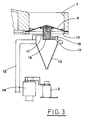
- the batching cask 8 previously filled, is shifted to the raised position, so that the elastic diaphragm 9 is kept taut to protrude upwards thus forming, in its upper part, an inclined convex surface, that is a truncated cone (fig. 3).
- Such displacement causes, in a spontaneous way, the removal of the product in excess that, due to gravity, comes down along the inclined surface formed by the elastic diaphragm 9 and is collected in a peripheral zone.
- the batching cask 8 is filled with a pre-established quantity of product, dose determined by the size of the same cask 8.
- the filling of the cask 8 with the pre-established quantity of product occurs without any mechanical action on the articles, in particular, without crushing or similar actions that could jeopardise their integrity.
- scraper means 22 skims the upper edge of the batching cask 8, removing the exceeding articles without crushing them, since the articles are pushed to fall freely on the inclined surface of the elastic diaphragm 9.
- the cam 18 controls the opening of the shutter 15 of the batching cask 8, so as to allow filling of the relative bottle 3 with the batched product (fig. 5).
- Such bottle 3 has been previously displaced to a raised position by the respective moving means 14, so as to come onto the exit of the hopper 13 that convey the articles 2 discharged by the batching cask 8.
- the bottle 3 already filled is carried again to the lowered position and directed orderly, by the distributor 20, to the line 5 leading away.
- the described method and device allow to fill the bottles 3 with a batched quantity of articles 2, without exerting any mechanical action i.e. compressing or crushing thereon.
- the subject method and device are therefore particularly efficient in case of batching products delicate or easily perishable in consequence of mechanical actions as those cited above, in particular granular and similar articles.
- the articles are batched in a spontaneous way by a single vertical upwards movement, that is imposed on the batching cask.
Description
- The present invention lies in the technical field concerning batching granular and similar articles, in particular delicate and easily perishable articles.
- There are used batching devices that fill bottles or other containers with a prefixed quantity of a product, e.g. granular, powdered or similar substances.
- Such devices usually have a rotating carousel equipped peripherally with a plurality of batching casks, distributed regularly, in contact with a space or an angular channel that is fed with the product to be put in the bottles.
- The lower parts of the casks are closed by a shutter that can be opened, in a special operative station, in order to unload the product into a hopper aimed at filling a bottle that is placed below.
- The aforementioned casks are designed to define the dose of the product to be put in each bottle.
- The casks are filled with the product put into the feeding channel of the carousel.
- There is provided a fixed scraper means that extends vertically in a shutter like fashion inside the carousel channel, that is up to the bottom of the same channel, e.i. at the level of the upper border of the casks.
- Therefore, during the rotation of the carousel, the product in the channel of the carousel is pushed by the scraper into the spaces defined by the aforementioned casks.
- In fact, the fixed scraper leaves the product in the feeding channel while scraping it at the level of the batching casks.
- Such batching method cannot be applied when the bottles are to be filled with delicate products, that cannot be crushed.
- In fact, the batching means compresses the product that is forced against it by the carousel rotation. Such mechanical action can crush a part of product and cause its damage.
- The object of the present invention is to propose such a method for batching granular and similar products that surely avoids crushing or damage of the product.
- The above mentioned object is obtained by the method according to
claim 1 and the device according toclaim 3. Preferred embodiments are characterised in the dependent claims. - The characteristics of the invention are pointed out in the following, with particular reference to the enclosed drawing, in which;
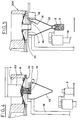
- fig. 1 shows a schematic, plan view of the batching device being the subject of the invention;
- fig. 2 shows a view, in vertical section, of such device, in the phase of feeding the product, according to the section line II-II of fig. 1;
- figs. 3, 4 and 5 show subsequent operative phases of the device, in a vertical section view, according to the section lines III-III, IV-IV, and V-V of fig. 1, respectively.
- With reference to the above mentioned figures, the
reference numeral 1 indicates the whole device for batchinggranular articles 2 destined to fillrelative bottles 3. - The
empty bottles 3 are fed along aline 4, in the direction indicated with the arrow A, and they are moved away, after having been filled, along aline 5 aligned with thesame feeding line 4. - The
device 1 includes acarousel 6 rotating step by step about a vertical axis, in the direction indicated with the arrow B. - The
carousel 6 has a peripheral ring-shaped channel 7 in correspondence with which a plurality ofbatching casks 8, having vertical axis, are situated regularly spaced apart from one another. - Each
batching cask 8 is fixed with itsupper lip 8a to a respectiveelastic diaphragm 9. - The
diaphragm 9 has the outer border fixed to the edge of a relativecircular opening 10 made in the bottom of thechannel 7, and is open centrally in correspondence to the zone fixed to therelative batching cask 8. - Below the
diaphragm 9, eachbatching cask 8 is supported, by means of asupport bracket 11, by avertical rod 12 that, as specified in the following, is designed to be moved vertically in accordance with alternate directions. - The
rod 12 supports also arespective hopper 13 coaxial with thecorrespondent batching cask 8. - Therefore, the
hopper 13 is movable together with thecorrespondent batching cask 8. - The
hopper 13 is designed to enter into arelative bottle 3 to be filled, that is joined to thecarousel 6 in correspondence with each of thebatching cask 8. - The
bottle 3 is supported on thecarousel 6 by respective movingmeans 14, adapted to move vertically in accordance with alternate directions. - The lower part of
batching casks 8 is closed by ashutter 15, swingable on apin 16 fastened to thehopper 13. - The
shutter 15 is normally kept closed by acounterweight 17, and can be opened at anunloading station 200 by special cam means 18. - The
bottles 3 fed by theline 4 are conveyed in an ordered manner to thecarousel 6 by a distributingmeans 19, such as rotating stars, in a suitable phase relation with thesame carousel 6. - A
similar distributor 20 transports filledbottles 3 from thecarousel 6 to theline 5 leading away. - The
carousel 6 is fed with thegranular articles 2 by afeeding hopper 21, placed over thechannel 7, in correspondence with astation 100 for filling thebatching casks 8. - A scraper means 22 is placed downstream of
such feeding hopper 21, according to the direction B of thecarousel 6 rotation. - According to the method for batching
granular products 2, carried out by the describeddevice 1, at the passage of abatching cask 8 in thefilling station 100, product is fed by thehopper 21 in a quantity slightly bigger than the pre-established dose, defined by the size of thesame batching casks 8. - Therefore, the
granular articles 2 fill thebatching cask 8 below, that, in this operative phase, is carried by therod 12 situated in a lowered position, so that theelastic diaphragm 9 is kept taut so as to protrude downwards thus forming, in its upper part, a concave surface that acts as mouth for the same batching cask 8 (fig. 2). - In its lower part, the
batching cask 8 is closed by theshutter 15, thus the product is kept inside thesame cask 8. - It is to be noted that, since the quantity of the product is bigger than the single dose, the
batching cask 8 is certainly completely filled, and the part of the product in excess is collected at the bottom of the mouth formed by theelastic diaphragm 9, over thesame cask 8. - In a subsequent station of the
carousel 6, thebatching cask 8, previously filled, is shifted to the raised position, so that theelastic diaphragm 9 is kept taut to protrude upwards thus forming, in its upper part, an inclined convex surface, that is a truncated cone (fig. 3). - Such displacement causes, in a spontaneous way, the removal of the product in excess that, due to gravity, comes down along the inclined surface formed by the
elastic diaphragm 9 and is collected in a peripheral zone. - In this way, the
batching cask 8 is filled with a pre-established quantity of product, dose determined by the size of thesame cask 8. - Obviously, it is possible to change the dose of product, according to the need, by changing the size of the
cask 8. - Otherwise, it is possible to use batching casks made of two joined parts of telescopic form, so as to allow to vary the relative capacity.
- Therefore, the filling of the
cask 8 with the pre-established quantity of product occurs without any mechanical action on the articles, in particular, without crushing or similar actions that could jeopardise their integrity. - The limited quantity of product remaining over the
cask 8 after the raising movement, can be removed by the scraper means 22, in a subsequent station of thecarousel 6. (fig. 4) - It is to be noted that, such scraper means 22 skims the upper edge of the
batching cask 8, removing the exceeding articles without crushing them, since the articles are pushed to fall freely on the inclined surface of theelastic diaphragm 9. - In the
subsequent discharge station 200 then, thecam 18 controls the opening of theshutter 15 of thebatching cask 8, so as to allow filling of therelative bottle 3 with the batched product (fig. 5). -
Such bottle 3 has been previously displaced to a raised position by therespective moving means 14, so as to come onto the exit of thehopper 13 that convey thearticles 2 discharged by thebatching cask 8. - The
bottle 3 already filled is carried again to the lowered position and directed orderly, by thedistributor 20, to theline 5 leading away. - In conclusion, the described method and device allow to fill the
bottles 3 with a batched quantity ofarticles 2, without exerting any mechanical action i.e. compressing or crushing thereon. - The subject method and device are therefore particularly efficient in case of batching products delicate or easily perishable in consequence of mechanical actions as those cited above, in particular granular and similar articles.
- It is also to be pointed out that the method in subject is carried out by a device a very simple in its construction, so it is very convenient also economically, either from the point of view of production costs or use cost.
- In particular, the articles are batched in a spontaneous way by a single vertical upwards movement, that is imposed on the batching cask.
- It is understood that what about has been described as a mere, non limitative example, therefore, possible constructive variations are covered by the protection of the present technical solution, as described above and claimed in the following.
Claims (6)
- Method for batching granular and similar articles by feeding a suitable quantity of granular articles (2) via a batching cask (8), characterised in that said batching cask (8), in its upper part, is joined to elastic means (9) designed to form an inclined concave surface that acts as a mouth for the same batching cask (8), so as to fill said batching cask (8) with said granular articles (2); and for displacing said batching cask (8) in a raised position in which said elastic means (9) are kept taut so as to protrude upwards thus forming an inclined convex surface, so as to provoke spontaneous removal of the articles (2) exceeding the preestablished dose, that fall along said inclined surface.
- Method, according to claim 1, characterised in that the exceeding articles (2), remaining on said filled batching cask (8), are removed by a scraper means (22) that is designed to skim the upper edge of the same batching cask (8).
- Device for the batching of granular and similar articles, comprising a rotating carousel (6) that is designed to carry a plurality of bottles (3), located in regular spaced apart relation with respect to each other, comprising a plurality of batching casks (8) carried by said carousel (6) over said bottles (3) characterised in that said batching casks (8), in their upper parts, are joined respectively to elastic means (9) designed to form an inclined concave surface that acts as feed opening for each of said batching casks (8) and in that it has means (12) designed to operate the motion of said batching casks (8) between a lowered position, in correspondence with a filling station (100), so as to fill said batching casks (8) with an appropriate quantity of articles (2), and a raised position, in which said elastic means (9) are kept taut so as to protrude upwards thus forming an inclined convex surface, so as to determine the spontaneous removal of the articles (2) exceeding the pre-established dose, by falling along said inclined surface.
- Device, according to claim 3, characterised in that said elastic means (9) consist of an elastic diaphragm that is integral, in correspondence with a central opening, to the top of a relative batching cask (8) and is peripherally fixed to the edge of a relative circular opening (10) made in the bottom of a channel (7) of said carousel (6).
- Device, according to claim 3, characterised in that it comprises, coaxial with each of said batching casks (8) and below the latter, a respective hopper (13) fastened to said operating means (12) and designed to enter a relative bottle (3) to be filled.
- Device, according to claim 3, characterised in that it comprises, downstream of said filling station (100), a scraper means (22) designed to skim the upper edge of said filled batching casks (8), remove the articles (2) in excess remaining on said batching casks (8).
Applications Claiming Priority (2)
| Application Number | Priority Date | Filing Date | Title |
|---|---|---|---|
| ITBO930288A IT1263443B (en) | 1993-06-23 | 1993-06-23 | METHOD FOR DOSING GRANULAR AND SIMILAR ITEMS AND DEVICE TO IMPLEMENT THIS METHOD. |
| ITBO930288 | 1993-06-23 |
Publications (3)
| Publication Number | Publication Date |
|---|---|
| EP0630816A2 EP0630816A2 (en) | 1994-12-28 |
| EP0630816A3 EP0630816A3 (en) | 1995-03-08 |
| EP0630816B1 true EP0630816B1 (en) | 1997-04-02 |
Family
ID=11339145
Family Applications (1)
| Application Number | Title | Priority Date | Filing Date |
|---|---|---|---|
| EP94830312A Expired - Lifetime EP0630816B1 (en) | 1993-06-23 | 1994-06-23 | Method for batching granular and similar articles and a device for carrying out such method |
Country Status (3)
| Country | Link |
|---|---|
| EP (1) | EP0630816B1 (en) |
| DE (1) | DE69402361T2 (en) |
| IT (1) | IT1263443B (en) |
Cited By (2)
| Publication number | Priority date | Publication date | Assignee | Title |
|---|---|---|---|---|
| CN106622010A (en) * | 2016-11-21 | 2017-05-10 | 宁翰 | Driving device applied to granule dispensing equipment |
| US10577186B2 (en) | 2011-08-18 | 2020-03-03 | Countlab, Inc. | Container filling machine |
Families Citing this family (3)
| Publication number | Priority date | Publication date | Assignee | Title |
|---|---|---|---|---|
| CA2629632C (en) | 2007-02-16 | 2013-06-18 | Countlab Inc. | A container filling machine |
| US8006468B2 (en) | 2008-04-14 | 2011-08-30 | Countlab Inc. | Container filling machine having vibration trays |
| CA2686751C (en) | 2008-12-02 | 2017-02-21 | Countlab, Inc. | A discrete article spacing apparatus for vibration trays |
Family Cites Families (3)
| Publication number | Priority date | Publication date | Assignee | Title |
|---|---|---|---|---|
| US2616652A (en) * | 1949-05-06 | 1952-11-04 | Rose Brothers Ltd | Feeding of powder and like fluent materials in equal quantities |
| GB690221A (en) * | 1949-07-28 | 1953-04-15 | Rose Brothers Ltd | Improvements in packaging apparatus for powdery, granular, flaky and other fluent solid materials |
| FR1562251A (en) * | 1968-02-22 | 1969-04-04 |
-
1993
- 1993-06-23 IT ITBO930288A patent/IT1263443B/en active IP Right Grant
-
1994
- 1994-06-23 DE DE69402361T patent/DE69402361T2/en not_active Expired - Fee Related
- 1994-06-23 EP EP94830312A patent/EP0630816B1/en not_active Expired - Lifetime
Cited By (3)
| Publication number | Priority date | Publication date | Assignee | Title |
|---|---|---|---|---|
| US10577186B2 (en) | 2011-08-18 | 2020-03-03 | Countlab, Inc. | Container filling machine |
| CN106622010A (en) * | 2016-11-21 | 2017-05-10 | 宁翰 | Driving device applied to granule dispensing equipment |
| CN106622010B (en) * | 2016-11-21 | 2019-11-15 | 宁翰 | A kind of driving device applied to granule dispensing equipment |
Also Published As
| Publication number | Publication date |
|---|---|
| DE69402361T2 (en) | 1997-07-10 |
| EP0630816A3 (en) | 1995-03-08 |
| EP0630816A2 (en) | 1994-12-28 |
| DE69402361D1 (en) | 1997-05-07 |
| ITBO930288A1 (en) | 1994-12-23 |
| IT1263443B (en) | 1996-08-05 |
| ITBO930288A0 (en) | 1993-06-23 |
Similar Documents
| Publication | Publication Date | Title |
|---|---|---|
| US5549189A (en) | Machine for automatically positioning and aligning containers | |
| WO1997011883A1 (en) | A packaging machine and a method for packaging units in portions | |
| WO2001066416A1 (en) | Automated filling machine and method | |
| US3924384A (en) | Method and apparatus for capping containers | |
| EP0327811A2 (en) | Cyclically operable apparatus for forming and filling bags | |
| US5280813A (en) | Particle loading system and method | |
| EP0630816B1 (en) | Method for batching granular and similar articles and a device for carrying out such method | |
| US6557691B2 (en) | Device for container rearranging machines, provided with automatic means for directing and dropping the container received | |
| WO1996004190A1 (en) | Feed tray for singularizing objects | |
| US4653674A (en) | Device for dispensing goods through annular dispensing port | |
| US3967659A (en) | Container filling apparatus | |
| JP3420569B2 (en) | Automatic parts distribution and orientation mechanism | |
| US4825623A (en) | Cyclically operable apparatus for forming and filing bags | |
| US5962816A (en) | Combinatorial weighing apparatus | |
| US5025612A (en) | Inverted tray container loading apparatus | |
| US3015378A (en) | Orientation apparatus for articles to be wrapped | |
| US11565894B2 (en) | Rotary discharge of containers from a depalletizer | |
| US4351374A (en) | Pouch filling machine | |
| US20220288642A1 (en) | Slack separation apparatus and method | |
| US3285294A (en) | Can filling machine and method | |
| US2328401A (en) | Filling machine | |
| JPS6341322A (en) | Silo device for bulk article | |
| US6066810A (en) | Combinatorial weighing apparatus | |
| US4965984A (en) | Method and apparatus for aligning elongated articles | |
| US3570211A (en) | Automatic traying apparatus |
Legal Events
| Date | Code | Title | Description |
|---|---|---|---|
| PUAI | Public reference made under article 153(3) epc to a published international application that has entered the european phase |
Free format text: ORIGINAL CODE: 0009012 |
|
| AK | Designated contracting states |
Kind code of ref document: A2 Designated state(s): DE ES FR GB NL |
|
| PUAL | Search report despatched |
Free format text: ORIGINAL CODE: 0009013 |
|
| AK | Designated contracting states |
Kind code of ref document: A3 Designated state(s): DE ES FR GB NL |
|
| 17P | Request for examination filed |
Effective date: 19950410 |
|
| GRAG | Despatch of communication of intention to grant |
Free format text: ORIGINAL CODE: EPIDOS AGRA |
|
| 17Q | First examination report despatched |
Effective date: 19960731 |
|
| GRAH | Despatch of communication of intention to grant a patent |
Free format text: ORIGINAL CODE: EPIDOS IGRA |
|
| GRAH | Despatch of communication of intention to grant a patent |
Free format text: ORIGINAL CODE: EPIDOS IGRA |
|
| GRAA | (expected) grant |
Free format text: ORIGINAL CODE: 0009210 |
|
| AK | Designated contracting states |
Kind code of ref document: B1 Designated state(s): DE ES FR GB NL |
|
| PG25 | Lapsed in a contracting state [announced via postgrant information from national office to epo] |
Ref country code: NL Effective date: 19970402 Ref country code: FR Effective date: 19970402 Ref country code: ES Free format text: THE PATENT HAS BEEN ANNULLED BY A DECISION OF A NATIONAL AUTHORITY Effective date: 19970402 |
|
| REF | Corresponds to: |
Ref document number: 69402361 Country of ref document: DE Date of ref document: 19970507 |
|
| EN | Fr: translation not filed | ||
| NLV1 | Nl: lapsed or annulled due to failure to fulfill the requirements of art. 29p and 29m of the patents act | ||
| PLBE | No opposition filed within time limit |
Free format text: ORIGINAL CODE: 0009261 |
|
| STAA | Information on the status of an ep patent application or granted ep patent |
Free format text: STATUS: NO OPPOSITION FILED WITHIN TIME LIMIT |
|
| 26N | No opposition filed | ||
| PG25 | Lapsed in a contracting state [announced via postgrant information from national office to epo] |
Ref country code: GB Free format text: LAPSE BECAUSE OF NON-PAYMENT OF DUE FEES Effective date: 19980623 |
|
| GBPC | Gb: european patent ceased through non-payment of renewal fee |
Effective date: 19980623 |
|
| PGFP | Annual fee paid to national office [announced via postgrant information from national office to epo] |
Ref country code: DE Payment date: 20000606 Year of fee payment: 7 |
|
| PG25 | Lapsed in a contracting state [announced via postgrant information from national office to epo] |
Ref country code: DE Free format text: LAPSE BECAUSE OF NON-PAYMENT OF DUE FEES Effective date: 20020403 |