EP0630673B1 - Method and apparatus for recovering crystals from slurry - Google Patents
Method and apparatus for recovering crystals from slurry Download PDFInfo
- Publication number
- EP0630673B1 EP0630673B1 EP94303720A EP94303720A EP0630673B1 EP 0630673 B1 EP0630673 B1 EP 0630673B1 EP 94303720 A EP94303720 A EP 94303720A EP 94303720 A EP94303720 A EP 94303720A EP 0630673 B1 EP0630673 B1 EP 0630673B1
- Authority
- EP
- European Patent Office
- Prior art keywords
- washing
- region
- slurry
- filter
- filter medium
- Prior art date
- Legal status (The legal status is an assumption and is not a legal conclusion. Google has not performed a legal analysis and makes no representation as to the accuracy of the status listed.)
- Expired - Lifetime
Links
Images

Classifications
-
- B—PERFORMING OPERATIONS; TRANSPORTING
- B01—PHYSICAL OR CHEMICAL PROCESSES OR APPARATUS IN GENERAL
- B01D—SEPARATION
- B01D33/00—Filters with filtering elements which move during the filtering operation
- B01D33/06—Filters with filtering elements which move during the filtering operation with rotary cylindrical filtering surfaces, e.g. hollow drums
- B01D33/073—Filters with filtering elements which move during the filtering operation with rotary cylindrical filtering surfaces, e.g. hollow drums arranged for inward flow filtration
-
- B—PERFORMING OPERATIONS; TRANSPORTING
- B01—PHYSICAL OR CHEMICAL PROCESSES OR APPARATUS IN GENERAL
- B01D—SEPARATION
- B01D33/00—Filters with filtering elements which move during the filtering operation
- B01D33/58—Handling the filter cake in the filter for purposes other than for regenerating the filter cake remaining on the filtering element
- B01D33/60—Handling the filter cake in the filter for purposes other than for regenerating the filter cake remaining on the filtering element for washing
-
- C—CHEMISTRY; METALLURGY
- C07—ORGANIC CHEMISTRY
- C07C—ACYCLIC OR CARBOCYCLIC COMPOUNDS
- C07C51/00—Preparation of carboxylic acids or their salts, halides or anhydrides
- C07C51/42—Separation; Purification; Stabilisation; Use of additives
- C07C51/43—Separation; Purification; Stabilisation; Use of additives by change of the physical state, e.g. crystallisation
Definitions
- the present invention relates to a method and an apparatus for recovering crystals from a slurry containing crystals of, for example, terephthalic acid.
- Terephthalic acid used as a starting material of polyethelene terephthalate and the like is produced by oxidizing paraxylene with a molecular oxygen-containing gas in a reaction medium based on acetic acid, wherein the resulting terephthalic acid will deposit in the reaction liqour in a crystalline form. Since the so-formed slurry of the crystalline terephthalic acid contains also the acetic acid solvent, the unreacted paraxylene, by-products and the catalyst components, it is necessary to separate the terephthalic acid crystals, from the slurry in order then to recover the terephthalic acid.
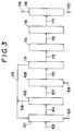
- Fig. 3 shows a schematic sequence diagram for a conventional method for recovering terephthalic acid crystals from such a slurry.
- the numeral 101 denotes an oxidizing reactor, to which a raw material mixture 102 composed of paraxylene as the starting material, acetic acid as the reaction medium and the catalyst is supplied, while supplying thereto at the same time a molecular oxygen-containing gas 103 to cause oxidation of the paraxylene into terephthalic acid.
- the crystal-containing slurry 104 formed in the oxidizing reactor 101 is transferred to a first stage solid/liquid separator 105 to effect a primary solid/liquid separation to separate the crystals from the liquid phase.
- the liquid phase 106 composed mainly of acetic acid separated here is returned to the oxidizing reactor 101, while the crude crystals 107 are forwarded to a re-disperser 108, where the crystals are suspended again in a medium of acetic acid 109 fed thereto in order to dissolve out the contaminants included in the crude crystal mass.
- the resulting reformed slurry 110 is then subjected to a secondary liquid/solid separation to separate the crystals from the liquid phase in a second stage solid/liquid separator 111.
- the separated liquid phase 112 composed mainly of acetic acid is transferred to the oxidizing reactor 101, while the purified crystals 113 are forwarded to a drier 114.
- the dried crystals 115 are stored in a silo 116.
- the recovered crystals 117 are then conveyed to a disperser 118, whereto water 119 is also supplied and is mixed with the crystals 117 to form an aqueous slurry 120 which is guided then to a refinery system to refine the crystals.
- DE-A-1 278 402 discloses a rotary drum filter for separating and washing solid particles with a minimum of water.
- the rotary drum is hollow and has peripheral compartments connectable to the interior of the drum. Water filtered through a filter cake on the perforated periphery of the drum enters into these compartments and is collected and drained therefrom separately. The water is recycled.
- the water is supplied to the exterior of the drum from a succession of spray heads arranged around the exterior of the drum. The waste liquid originating from one spray head is collected and supplied to the spray head located immediately upstream of the first spray head with regard to the direction of rotation of the drum.
- EP-A-0 406 424 discloses a method and apparatus for recovering crystals from a crystal-containing slurry using a rotary filter having a rotating cylindrical filter medium. Crystal-containing slurry is filtered in a filtering region of the rotating filter medium so as to separate the crystals as a filter cake on the filter medium. This filter cake is then washed in a washing region by supplying washing liquid to the exterior of the filter medium. Upon passing once through the filter cake the spent washing liquid is collected and stored in a waste tank prior to being disposed of. Where the crystals are crystals of terephthalic acid the spent washing liquid will contain acetic acid of low concentration.
- a method of recovering crystals from a crystal-containing slurry using a rotary filter having a rotating cylindrical filter medium comprising:
- the rotating cylindrical filter medium may, for example, have three washing regions, said first washing region, said last washing region and an intermediate washing region provided therebetween, the washing liquid supplied to the intermediate washing region being the spent washing liquid collected from said last washing region and the washing liquid supplied to said first washing region being the spent washing liquid collected from the intermediate washing region.
- apparatus for recovering crystals from a crystal-containing slurry comprising:
- washing regions there are three washing regions, an intermediate washing region being provided between said first and last washing regions, and the supply means are arranged:
- the hereinafter described and illustrated method and apparatus are especially suitable for recovering terephthalic acid crystals, although they can also be used for recovering various other crystalline products, such as hydroquinone, resorcin etc., from slurries containing them.
- a conventional rotary vacuum filter containing a rotating cylindrical filter medium operated by maintaining a reduced pressure inside the filter medium for establishing the filtering pressure drop across the filter medium may be used, though it is rather preferred to use a rotary pressure filter operated by pressurizing the outside of its rotating filter medium for establishing the filtering pressure drop.
- a rotary pressure/sucking filter may also be used.
- a part of the solvent of the slurry becomes vaporized due to the lowering of the pressure, whereby the slurry temperature is lowered by being deprived of the latent heat of vaporization, so that the solubility of the solutes existing at their saturation points in the solvent of the slurry is decreased to force deposition thereof in a form of fine particles which fill up the liquid flow paths between the solid particles in the filter cake and cause stuffing of the filter medium.
- a rotary pressure filter and a rotary pressure/sucking filter undergo less tendency to stuffing of the filter medium than that of rotary vaccum filter, since occurrence of a slurry temperature lowering due to the solvent vaporization is avoided in them.
- the filter cake formed on the filter medium is washed in a series of steps on the rotating filter medium in a plurality of washing regions subsequent to the filtering region of the rotary filter to a considerable degree, so that the number of solid/liquid separators and their accessories required for recovering the crystals are reduced as compared with those of the conventional techniques.
- the primary slurry containing the crude terephthalic acid crystals from an oxidizing reactor is filtered by a rotary filter on a rotating filter medium and the resulting filter cake is washed several times on the rotating filter medium with a washing liquid, whereupon the washed filter cake is re-suspended to form a secondary slurry which is sent directly to a disperser for forming the starting slurry to be supplied to the crystal refinery system.
- a series of a primary solid/liquid separator, a re-disperser, a drier and a silo with their accessories in the first process step of the conventional technique are dispensed with.
- the contaminant components included in the filter cake can be recovered and reclaimed effectively by washing the filter cake on the rotating filter medium in a plurality of washing regions by supplying a washing liquid to and separating the spent washing liquid from each of the washing regions in such a manner that a fresh washing liquid is supplied to the washing region of the forefront in the moving direction of the rotating filter medium, while supplying any one of washing regions on the aft side of said forefront, seen in the moving direction of the rotating filter medium, with the spent washing liquid separated in the washing region neighboring said one washing region on the fore side, seen in the moving direction of the filter medium, and recycling the spent washing liquid from the washing region rearmost in the moving direction of the filter medium to the slurry preparation step together with the filtrate of the filtering region.
- the spent washing liquid from the final washing region namely, the washing region rearmost in the rotating direction of the filter medium
- This spent washing liquid from the washing region rearmost in the rotating direction of the filter medium is recycled to the oxidizing reactor to reuse it as the reaction medium for the oxidation of paraxylene.
- Fig. 1 shows a schematic flow diagram of an apparatus for recovering crystals from a crystal-containing slurry according to a preferred embodiment of the present invention.
- the numeral 1 denotes an oxidizing reactor which is constructed so as to realize an oxidizing reaction of the raw material by supplying thereto the starting raw material mixture via a supply line L1 and a molecular oxygen-containing gas via a gas supply line L2.
- An exhaustion line L3 for discharging out the resulting slurry of the oxidizing reaction communicates from the bottom of the oxidizing reactor 1 to a flash drum 2.
- a slurry supply line L4 including a slurry pump 3 communicates from the bottom of the flash drum 2 to a rotary pressure filter 4 at a slurry inlet 5.
- the rotary pressure filter 4 having the slurry inlet 5 at its bottom has a casing 7 provided with a filter cake discharge gate 6 arranged downwards.
- a horizontal cylindrical filter medium 9 is disposed within the casing 7 of the rotary pressure filter 4 with its lower portion being immersed in a sump 8 of the slurry supplied thereto so as to constitute a filtering region 9a and is rotatingly driven clockwise in Fig. 1 at a constant speed by a not-shown motor under intermediation by a reduction gear.
- a plurality of spray nozzles 11a, 11b, 11c constituting a spraying unit for spraying a washing liquid onto the filter cake on the filter medium are disposed outside the rotating filter medium 9 each correspondingly, but in the reverse sense, in each of a plurality of washing regions 9b, 9c, 9d provided subsequently to the filtering region 9a above the slurry sump 8 and allotted successively in a row in the rotating direction of the filter medium.
- spent washing liquid receivers 12a, 12b are disposed inside the cylindrical filter medium in a paired relation with the spray nozzles 11a, 11b except the spray nozzle 11c of the washing region rearmost in the rotating direction.
- a gas blow nozzle 13 is located inside the filter medium 9 in a filter cake removal region 9e at a portion adjacent the cake discharge gate 6 and serves for blowing N 2 gas from inside to the filter cake layer to remove it off the filter medium 9.
- An exhaustion line L5 for exhausting the spent washing liquid for the rearmost spray nozzle in the rotating direction together with the filtrate collected in the bottom portion of the rotating filter medium communicates therefrom to a filtrate reservoir 14 which is connected with the oxidizing reactor 1 by a line L6 having a pump 15.
- a line L7 is connected with the nozzle 11a in order to supply pure water as the fresh washing liquid.
- the receiver 12a is connected with a first spent washing liquid storage tank 16 via a line L8 and the bottom of the storage tank 16 is connected with the spray nozzle 11b via a line L9 having a pump 17.
- the receiver 12b is connected with a second spent washing liquid storage tank 18 via a line L10 and the bottom of the storage tank 18 is connected with the spray nozzle 11c via a line L11 having a pump 19.
- the casing 7 is connected at its upper portion with a line L12 for pressurizing the outside of the rotating filter medium and its cake discharge gate 6 is connected with a disperser 21 via a line L13.
- the disperser 21 is connected with a line L14 for supplying pure water thereto and at its bottom with a line L15 having an interposed pump 22 and communicating to a refinery system.
- the flash drum 2 is connected with a condenser 23 by lines L16 and L17 for cooling the vapor from the flash drum 2 to condense it and to return the condensate thereto.
- the condenser 23 is connected with lines L18, L19 and L20 for supplying the cooling water thereto, for discharging the spent cooling water therefrom and for exhausting the trapped non-condensing gas out of it, respectively.
- the oxidizing reactor 1 is supplied with a raw material mixture composed of paraxylene as the starting material, acetic acid as the solvent and a catalyst via the line L1 and also with a molecular oxygen-containing gas, such as the air, via the line 2 and in which paraxylene is oxidized by the molecular oxygen into terephthalic acid.
- the resulting reaction product mixture in the form of a slurry is sent from the oxidizing reactor 1 via the line L3 to the flash drum 2 where it is exposed to a reduced pressure and is flashed to cause a temperature decrease.
- the vapor phase is cooled by the condenser 23 to condense the condensible components into a condensate which is returned to the flash drum 2 via the line L17 and the non-condensible gas is exhausted out via the line L20.
- the slurry left in the flash drum 2 is guided via the line L4 to the slurry inlet 5 of the rotary pressure filter 4 by the pump 3.
- pure water is supplied as the washing liquid via the line L7 to the spray nozzle 11a in the washing region 9d of the forefront in the rotating direction of the filter medium 9 and is sprayed to wash the filter cake.
- the spent washing water passed through the filter cake and the filter medium and collected in the receiver 12a is guided through the line L8 to the first spent washing liquid storage tank 16, from which it is supplied to the spray nozzle 11b of the washing region 9c neighboring the above-mentioned forefront washing region 9d in the aft side in the rotating direction of the filter medium by the pump 17 and is sprayed to wash the filter cake in the washing region 9c.
- the spent washing water collected in the receiver 12b of the washing region 9c is guided through the line L10 to the second spent washing liquid storage tank 18, from which it is supplied to the spray nozzle llc of the washing region 9b rearmost in the rotating direction of the filter medium by the pump 19 and is sprayed to wash the filter cake.
- the concentration of the contaminant components, such as acetic acid and unreacted starting material, in the spent washing water becomes increased successively in the washing regions towards aft the rotating direction of the filter medium.
- the spent washing water of the washing region 9b rearmost in the rotating direction which has the highest concentration of such contaminant components, is gathered with the filtrate from the filtering region 9a in the bottom portion of the horizontal cylindrical filter medium, from which it is recycled, namely, together with the filtrate, to the oxidizing reactor 1 via the line L6 by the pump 15 to reuse them in the oxidation reaction.
- the filter cake of crystals retained on the rotating filter medium in a layer is cleaned to a considerable degree by a repeated washing (three times in this embodiment) in the washing regions 9b - 9d under separation of each spent washing water from the crystals with final washing by pure water, so that the contaminant components, such as acetic acid etc., occluded in between the crystals can efficiently be removed.
- the washed filter cake left on the rotating filter medium in a layer is blown off from the filter medium 9 in the filter cake removing region 9e by blowing an inert gas, such as N 2 gas, from inside onto the filter cake layer using a gas blowing nozzle 13 and the so-removed filter cake is discharged from the cake discharge gate 6 into the disperser 21, where the filter cake is re-suspended in pure water supplied thereto via the line L14 to form a secondary slurry which is supplied to the refinery system via the line L15 by the slurry pump 22.
- an inert gas such as N 2 gas
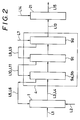
- Fig. 2 the procedures of the method according to the present invention described above are explained schematically in a flow sequence diagram. As shown, the slurry containing crystals of terephthalic acid formed in the oxidizing reactor 1 is guided to the rotary pressure filter 4 via the line L3,L4.
- a plurality of solid/liquid separation steps of filtration and washing purification are performed in the filtering region 9a and the washing regions 9b, 9c and 9d, wherein the washing liquid supplied via the line L7 is used for washing the filter cake in the washing region 9d in the forefront in the rotating direction of the filter medium and the spent washing liquid thereof is used for washing the filter cake in the washing region 9c neighboring the said forefront washing region 9d in the aft side in the rotating direction of the filter medium by supplying it thereto as the washing liquid therefor via the line L8,L9 and, further, the spent washing liquid of this washing region 9c is used for washing the filter cake in the washing region 9b rearmost in the rotating direction of the filter medium by supplying it thereto as the- washing liquid therefor via the line L10,L11.
- the spent washing liquid separated in the washing region 9b rearmost in the rotating direction of the filter medium is returned together with the filtrate from the filtering region 9a to the oxidizing reactor 1 via the line L5,L6.
- the filter cake of the crystals washed finally by pure water in the washing region 9d in the forefront in the rotating direction is collected and sent to the disperser 21 via the line L13.
- the method according to the present invention can afford to recover crystals from a crystal-containing slurry using a simplified apparatus by a simple operation efficiently with the simultaneous attainment of an effective reclamation of the contaminant components included in between the crystals in the filter cake, such as acetic acid etc., by recovering them at higher concentrations, since the procedures of washing of the filter cake and separation of the spent washing liquid are repeated in a plurality of washing regions settled within the rotary filter by using the spent washing water separated in any one of the washing region as the washing liquid for the washing region neighboring the said one washing region on the aft side in the moving direction of the filter medium.
Landscapes
- Chemical & Material Sciences (AREA)
- Organic Chemistry (AREA)
- Chemical Kinetics & Catalysis (AREA)
- Crystallography & Structural Chemistry (AREA)
- Engineering & Computer Science (AREA)
- Oil, Petroleum & Natural Gas (AREA)
- Organic Low-Molecular-Weight Compounds And Preparation Thereof (AREA)
- Separation Using Semi-Permeable Membranes (AREA)
- Filtration Of Liquid (AREA)
- Treatment Of Sludge (AREA)
- Centrifugal Separators (AREA)
- Application Of Or Painting With Fluid Materials (AREA)
Abstract
Description
- The present invention relates to a method and an apparatus for recovering crystals from a slurry containing crystals of, for example, terephthalic acid.
- Terephthalic acid used as a starting material of polyethelene terephthalate and the like is produced by oxidizing paraxylene with a molecular oxygen-containing gas in a reaction medium based on acetic acid, wherein the resulting terephthalic acid will deposit in the reaction liqour in a crystalline form. Since the so-formed slurry of the crystalline terephthalic acid contains also the acetic acid solvent, the unreacted paraxylene, by-products and the catalyst components, it is necessary to separate the terephthalic acid crystals, from the slurry in order then to recover the terephthalic acid.
- Fig. 3 shows a schematic sequence diagram for a conventional method for recovering terephthalic acid crystals from such a slurry. In Fig. 3, the
numeral 101 denotes an oxidizing reactor, to which araw material mixture 102 composed of paraxylene as the starting material, acetic acid as the reaction medium and the catalyst is supplied, while supplying thereto at the same time a molecular oxygen-containinggas 103 to cause oxidation of the paraxylene into terephthalic acid. - In this conventional technique for recovering terephthalic acid crystals, the crystal-containing
slurry 104 formed in the oxidizingreactor 101 is transferred to a first stage solid/liquid separator 105 to effect a primary solid/liquid separation to separate the crystals from the liquid phase. Theliquid phase 106 composed mainly of acetic acid separated here is returned to the oxidizingreactor 101, while thecrude crystals 107 are forwarded to are-disperser 108, where the crystals are suspended again in a medium ofacetic acid 109 fed thereto in order to dissolve out the contaminants included in the crude crystal mass. The resulting reformedslurry 110 is then subjected to a secondary liquid/solid separation to separate the crystals from the liquid phase in a second stage solid/liquid separator 111. The separatedliquid phase 112 composed mainly of acetic acid is transferred to the oxidizingreactor 101, while the purifiedcrystals 113 are forwarded to adrier 114. Thedried crystals 115 are stored in asilo 116. The recoveredcrystals 117 are then conveyed to adisperser 118, wheretowater 119 is also supplied and is mixed with thecrystals 117 to form anaqueous slurry 120 which is guided then to a refinery system to refine the crystals. - The conventional technique for recovering crystals from a slurry thus requires a large number of process steps with a correspondingly large number of devices and instruments, resulting in higher production costs for the final product.
- DE-A-1 278 402 discloses a rotary drum filter for separating and washing solid particles with a minimum of water. The rotary drum is hollow and has peripheral compartments connectable to the interior of the drum. Water filtered through a filter cake on the perforated periphery of the drum enters into these compartments and is collected and drained therefrom separately. The water is recycled. The water is supplied to the exterior of the drum from a succession of spray heads arranged around the exterior of the drum. The waste liquid originating from one spray head is collected and supplied to the spray head located immediately upstream of the first spray head with regard to the direction of rotation of the drum.
- BHS-Fest Druck-Vakuum Filter, 9 June 1961, Huttenwerk Sonthofen, discloses a rotary drum filter generally similar to that disclosed in DE-A-1 278 402.
- EP-A-0 406 424 discloses a method and apparatus for recovering crystals from a crystal-containing slurry using a rotary filter having a rotating cylindrical filter medium. Crystal-containing slurry is filtered in a filtering region of the rotating filter medium so as to separate the crystals as a filter cake on the filter medium. This filter cake is then washed in a washing region by supplying washing liquid to the exterior of the filter medium. Upon passing once through the filter cake the spent washing liquid is collected and stored in a waste tank prior to being disposed of. Where the crystals are crystals of terephthalic acid the spent washing liquid will contain acetic acid of low concentration.
- According to one aspect of the present invention there is provided a method of recovering crystals from a crystal-containing slurry using a rotary filter having a rotating cylindrical filter medium, the method comprising:
- supplying the crystal-containing slurry from a slurry preparation step to the rotary filter, the rotary filter having a plurality of washing regions including at least a first washing region and a last washing region, the last washing region being downstream of the first washing region in the direction of rotation of the filter medium;
- filtering the supplied slurry in a filtering region of the rotary filter so as to form a filtrate and to separate the crystals as a filter cake on the filter medium;
- washing the filter cake on the rotating filter medium in the plurality of washing regions by supplying washing liquid to the washing regions and collecting the spent washing liquid from each of the washing regions, the washing liquid supplied to said last washing region being fresh washing liquid and the washing liquid supplied to the first washing region being spent washing liquid collected from the washing region immediately downstream of the first washing region in the direction of rotation of the filter medium;
- supplying to the slurry preparation step the spent washing liquid collected from the first washing region, together with the filtrate from the filtering region; and
- collecting the washed filter cake from the filter medium.
- The rotating cylindrical filter medium may, for example, have three washing regions, said first washing region, said last washing region and an intermediate washing region provided therebetween, the washing liquid supplied to the intermediate washing region being the spent washing liquid collected from said last washing region and the washing liquid supplied to said first washing region being the spent washing liquid collected from the intermediate washing region.
- According to a further aspect of the present invention there is provided apparatus for recovering crystals from a crystal-containing slurry, the apparatus comprising:
- slurry supply apparatus for supplying the crystal-containing slurry;
- a rotary filter having:
- a casing for receiving the crystal-containing slurry from the slurry supply apparatus;
- a cylindrical filter medium for effecting filtration of the crystal-containing slurry, the medium being rotatable within the casing so as to pass the cylindrical surface of the medium through, in order, a filtering region for separating the crystals from the slurry to form a filtrate and a filter cake, a plurality of washing regions ranging from a first, upstream region to a last, downstream region, said washing regions being for washing the filter cake, and a filter cake removing region for the removal of the washed filter cake;
- a plurality of spray units for spraying washing liquid onto the filter cake formed on the filter medium, each of said washing regions having an associated said spray unit positioned outwardly of the cylindrical filter medium;
- at least one spent washing liquid receiver for receiving washing liquid passed through the filter medium and the filter cake, the or each washing region except for said first washing region being provided with a said receiver positioned inwardly of the cylindrical filter medium in opposition to its associated spray unit; and
- means for collecting the washed filter cake from the filter medium in the filter cake removing region; means for supplying fresh washing liquid to the spray unit associated with said last washing region and for supplying the spray unit associated with said first washing region with spent washing liquid from the spent washing liquid receiver of the washing region immediately downstream of said first washing region in the direction of rotation of the filter medium; and means for returning to the slurry supply apparatus spent washing liquid from said first washing region, together with the filtrate from the filtering region.
- Advantageously there are three washing regions, an intermediate washing region being provided between said first and last washing regions, and the supply means are arranged:
- to supply to the spray unit associated with the intermediate washing region spent washing liquid from the spent washing liquid receiver of said last washing region; and
- to supply to the spray unit associated with said first washing region spent washing liquid from the spent washing liquid receiver of the intermediate washing region.
- The present invention will be further described hereinafter with reference to the following description of an exemplary embodiment and the accompanying drawings, in which:-
- Fig. 1 is a schematic flow diagram for a preferred embodiment of the apparatus for recovering crystals from a slurry according to the present invention;
- Fig. 2 is a schematic sequence diagram for the method for recovering crystals from a slurry according to the present invention;
- Fig. 3 is a schematic sequence diagram for a typical conventional method for recovering crystals from a slurry.
- The hereinafter described and illustrated method and apparatus are especially suitable for recovering terephthalic acid crystals, although they can also be used for recovering various other crystalline products, such as hydroquinone, resorcin etc., from slurries containing them.
- For the rotary filter to be employed according to the present invention, a conventional rotary vacuum filter containing a rotating cylindrical filter medium operated by maintaining a reduced pressure inside the filter medium for establishing the filtering pressure drop across the filter medium may be used, though it is rather preferred to use a rotary pressure filter operated by pressurizing the outside of its rotating filter medium for establishing the filtering pressure drop. A rotary pressure/sucking filter may also be used. In a rotary vacuum filter operated by maintaining a reduced pressure inside the rotating filter medium, a part of the solvent of the slurry becomes vaporized due to the lowering of the pressure, whereby the slurry temperature is lowered by being deprived of the latent heat of vaporization, so that the solubility of the solutes existing at their saturation points in the solvent of the slurry is decreased to force deposition thereof in a form of fine particles which fill up the liquid flow paths between the solid particles in the filter cake and cause stuffing of the filter medium. In contrast thereto, a rotary pressure filter and a rotary pressure/sucking filter undergo less tendency to stuffing of the filter medium than that of rotary vaccum filter, since occurrence of a slurry temperature lowering due to the solvent vaporization is avoided in them.
- According to the present invention, the filter cake formed on the filter medium is washed in a series of steps on the rotating filter medium in a plurality of washing regions subsequent to the filtering region of the rotary filter to a considerable degree, so that the number of solid/liquid separators and their accessories required for recovering the crystals are reduced as compared with those of the conventional techniques. By way of example, in the case of recovering terephthalic acid crystals by the method according to the present invention, the primary slurry containing the crude terephthalic acid crystals from an oxidizing reactor is filtered by a rotary filter on a rotating filter medium and the resulting filter cake is washed several times on the rotating filter medium with a washing liquid, whereupon the washed filter cake is re-suspended to form a secondary slurry which is sent directly to a disperser for forming the starting slurry to be supplied to the crystal refinery system. In this manner, a series of a primary solid/liquid separator, a re-disperser, a drier and a silo with their accessories in the first process step of the conventional technique are dispensed with.
- The contaminant components included in the filter cake can be recovered and reclaimed effectively by washing the filter cake on the rotating filter medium in a plurality of washing regions by supplying a washing liquid to and separating the spent washing liquid from each of the washing regions in such a manner that a fresh washing liquid is supplied to the washing region of the forefront in the moving direction of the rotating filter medium, while supplying any one of washing regions on the aft side of said forefront, seen in the moving direction of the rotating filter medium, with the spent washing liquid separated in the washing region neighboring said one washing region on the fore side, seen in the moving direction of the filter medium, and recycling the spent washing liquid from the washing region rearmost in the moving direction of the filter medium to the slurry preparation step together with the filtrate of the filtering region. In recovering terephthalic acid crystals by the method according to the present invention, the spent washing liquid from the final washing region, namely, the washing region rearmost in the rotating direction of the filter medium, has a considerably high acetic acid concentration due to the incremental accumulation thereof by the repeated use of the spent washing liquid from the preceding regions as the washing liquid successively. This spent washing liquid from the washing region rearmost in the rotating direction of the filter medium is recycled to the oxidizing reactor to reuse it as the reaction medium for the oxidation of paraxylene.
- In this manner, by the method and apparatus for recovering crystals from a slurry according to the present invention, the procedures of repeated washing of the filter cake and solid/liquid separation of the slurry are realized in one and the same rotary filter, so that the number of solid/liquid separators to be incorporated and the accessories for them can be reduced, whereby the construction of the entire recovery system can be simplified and an econimization of energy and an improvement of the operation of the system are attainable.
-
- Fig. 1 shows a schematic flow diagram of an apparatus for recovering crystals from a crystal-containing slurry according to a preferred embodiment of the present invention. In Fig. 1, the
numeral 1 denotes an oxidizing reactor which is constructed so as to realize an oxidizing reaction of the raw material by supplying thereto the starting raw material mixture via a supply line L1 and a molecular oxygen-containing gas via a gas supply line L2. An exhaustion line L3 for discharging out the resulting slurry of the oxidizing reaction communicates from the bottom of the oxidizingreactor 1 to a flash drum 2. A slurry supply line L4 including a slurry pump 3 communicates from the bottom of the flash drum 2 to arotary pressure filter 4 at a slurry inlet 5. - The
rotary pressure filter 4 having the slurry inlet 5 at its bottom has a casing 7 provided with a filter cake discharge gate 6 arranged downwards. A horizontal cylindrical filter medium 9 is disposed within the casing 7 of therotary pressure filter 4 with its lower portion being immersed in asump 8 of the slurry supplied thereto so as to constitute afiltering region 9a and is rotatingly driven clockwise in Fig. 1 at a constant speed by a not-shown motor under intermediation by a reduction gear. A plurality ofspray nozzles washing regions filtering region 9a above theslurry sump 8 and allotted successively in a row in the rotating direction of the filter medium. As a spent washing liquid receiving means for receiving the spent washing liquid sprayed onto the filter cake outside the filter medium and passed therethrough to the inside thereof, spent washingliquid receivers spray nozzles spray nozzle 11c of the washing region rearmost in the rotating direction. Agas blow nozzle 13 is located inside the filter medium 9 in a filtercake removal region 9e at a portion adjacent the cake discharge gate 6 and serves for blowing N2 gas from inside to the filter cake layer to remove it off the filter medium 9. - An exhaustion line L5 for exhausting the spent washing liquid for the rearmost spray nozzle in the rotating direction together with the filtrate collected in the bottom portion of the rotating filter medium communicates therefrom to a
filtrate reservoir 14 which is connected with the oxidizingreactor 1 by a line L6 having apump 15. A line L7 is connected with thenozzle 11a in order to supply pure water as the fresh washing liquid. Thereceiver 12a is connected with a first spent washingliquid storage tank 16 via a line L8 and the bottom of thestorage tank 16 is connected with thespray nozzle 11b via a line L9 having apump 17. Thereceiver 12b is connected with a second spent washingliquid storage tank 18 via a line L10 and the bottom of thestorage tank 18 is connected with thespray nozzle 11c via a line L11 having apump 19. The casing 7 is connected at its upper portion with a line L12 for pressurizing the outside of the rotating filter medium and its cake discharge gate 6 is connected with adisperser 21 via a line L13. Thedisperser 21 is connected with a line L14 for supplying pure water thereto and at its bottom with a line L15 having an interposedpump 22 and communicating to a refinery system. - The flash drum 2 is connected with a
condenser 23 by lines L16 and L17 for cooling the vapor from the flash drum 2 to condense it and to return the condensate thereto. Thecondenser 23 is connected with lines L18, L19 and L20 for supplying the cooling water thereto, for discharging the spent cooling water therefrom and for exhausting the trapped non-condensing gas out of it, respectively. - The recovery of the crystals from the slurry using the apparatus explained above is carried out as follows:
- The oxidizing
reactor 1 is supplied with a raw material mixture composed of paraxylene as the starting material, acetic acid as the solvent and a catalyst via the line L1 and also with a molecular oxygen-containing gas, such as the air, via the line 2 and in which paraxylene is oxidized by the molecular oxygen into terephthalic acid. - The resulting reaction product mixture in the form of a slurry is sent from the oxidizing
reactor 1 via the line L3 to the flash drum 2 where it is exposed to a reduced pressure and is flashed to cause a temperature decrease. The vapor phase is cooled by thecondenser 23 to condense the condensible components into a condensate which is returned to the flash drum 2 via the line L17 and the non-condensible gas is exhausted out via the line L20. The slurry left in the flash drum 2 is guided via the line L4 to the slurry inlet 5 of therotary pressure filter 4 by the pump 3. - By rotating the horizontal cylindrical filter medium 9 clockwise (seen in Fig. 1) within the casing 7 of the
rotary pressure filter 4 while pressurizing the outside of thecylindrical filter medium 4 by pressing an inert gas, such as N2, into the casing 7, the slurry contacting with the cylindrical rotating filter medium 9 in its bottom portion constituting thefiltering region 9a immersed in the slurry is subjected to filtration by the pressure gradient across the filter medium to retain the crystals on the filter medium 9 as the filter cake while successively moving upwards in accordance with the rotation of the filter medium 9. The filter cake on the filter medium 9 passes then through thewashing regions spray nozzle 11a in thewashing region 9d of the forefront in the rotating direction of the filter medium 9 and is sprayed to wash the filter cake. The spent washing water passed through the filter cake and the filter medium and collected in thereceiver 12a is guided through the line L8 to the first spent washingliquid storage tank 16, from which it is supplied to thespray nozzle 11b of thewashing region 9c neighboring the above-mentionedforefront washing region 9d in the aft side in the rotating direction of the filter medium by thepump 17 and is sprayed to wash the filter cake in thewashing region 9c. The spent washing water collected in thereceiver 12b of thewashing region 9c is guided through the line L10 to the second spent washingliquid storage tank 18, from which it is supplied to the spray nozzle llc of thewashing region 9b rearmost in the rotating direction of the filter medium by thepump 19 and is sprayed to wash the filter cake. - By supplying, in this manner, any one of the washing regions on the aft side of the washing region of the forefront, seen in the moving direction of the rotating filter medium, with the spent washing water separated in the washing region neighboring the said one washing region on the fore side, seen in the moving direction of the filter medium, the concentration of the contaminant components, such as acetic acid and unreacted starting material, in the spent washing water becomes increased successively in the washing regions towards aft the rotating direction of the filter medium. The spent washing water of the
washing region 9b rearmost in the rotating direction, which has the highest concentration of such contaminant components, is gathered with the filtrate from thefiltering region 9a in the bottom portion of the horizontal cylindrical filter medium, from which it is recycled, namely, together with the filtrate, to the oxidizingreactor 1 via the line L6 by thepump 15 to reuse them in the oxidation reaction. - In this manner, the filter cake of crystals retained on the rotating filter medium in a layer is cleaned to a considerable degree by a repeated washing (three times in this embodiment) in the
washing regions 9b - 9d under separation of each spent washing water from the crystals with final washing by pure water, so that the contaminant components, such as acetic acid etc., occluded in between the crystals can efficiently be removed. The washed filter cake left on the rotating filter medium in a layer is blown off from the filter medium 9 in the filtercake removing region 9e by blowing an inert gas, such as N2 gas, from inside onto the filter cake layer using agas blowing nozzle 13 and the so-removed filter cake is discharged from the cake discharge gate 6 into thedisperser 21, where the filter cake is re-suspended in pure water supplied thereto via the line L14 to form a secondary slurry which is supplied to the refinery system via the line L15 by theslurry pump 22. - In Fig. 2, the procedures of the method according to the present invention described above are explained schematically in a flow sequence diagram. As shown, the slurry containing crystals of terephthalic acid formed in the oxidizing
reactor 1 is guided to therotary pressure filter 4 via the line L3,L4. In therotary pressure filter 4, a plurality of solid/liquid separation steps of filtration and washing purification are performed in thefiltering region 9a and thewashing regions washing region 9d in the forefront in the rotating direction of the filter medium and the spent washing liquid thereof is used for washing the filter cake in thewashing region 9c neighboring the saidforefront washing region 9d in the aft side in the rotating direction of the filter medium by supplying it thereto as the washing liquid therefor via the line L8,L9 and, further, the spent washing liquid of thiswashing region 9c is used for washing the filter cake in thewashing region 9b rearmost in the rotating direction of the filter medium by supplying it thereto as the- washing liquid therefor via the line L10,L11. The spent washing liquid separated in thewashing region 9b rearmost in the rotating direction of the filter medium is returned together with the filtrate from thefiltering region 9a to the oxidizingreactor 1 via the line L5,L6. The filter cake of the crystals washed finally by pure water in thewashing region 9d in the forefront in the rotating direction is collected and sent to thedisperser 21 via the line L13. - As described above, the method according to the present invention can afford to recover crystals from a crystal-containing slurry using a simplified apparatus by a simple operation efficiently with the simultaneous attainment of an effective reclamation of the contaminant components included in between the crystals in the filter cake, such as acetic acid etc., by recovering them at higher concentrations, since the procedures of washing of the filter cake and separation of the spent washing liquid are repeated in a plurality of washing regions settled within the rotary filter by using the spent washing water separated in any one of the washing region as the washing liquid for the washing region neighboring the said one washing region on the aft side in the moving direction of the filter medium.
Claims (8)
- A method of recovering crystals from a crystal-containing slurry using a rotary filter (4) having a rotating cylindrical filter medium (9), the method comprising:supplying the crystal-containing slurry from a slurry preparation step to the rotary filter (4), the rotary filter (4) having a plurality of washing regions (9b,9c,9d) including at least a first washing region (9b) and a last washing region (9d), the last washing region (9d) being downstream of the first washing region (9b) in the direction of rotation of the filter medium (9);filtering the supplied slurry in a filtering region (9a) of the rotary filter (4) so as to form a filtrate and to separate the crystals as a filter cake on the filter medium (9);washing the filter cake on the rotating filter medium (9) in the plurality of washing regions (9b,9c,9d) by supplying washing liquid to the washing regions and collecting the spent washing liquid from each of the washing regions, the washing liquid supplied to said last washing region (9d) being fresh washing liquid and the washing liquid supplied to the first washing region (9b) being spent washing liquid collected from the washing region (9c) immediately downstream of the first washing region (9b) in the direction of rotation of the filter medium (9);supplying to the slurry preparation step the spent washing liquid collected from the first washing region (9b), together with the filtrate from the filtering region (9a); andcollecting the washed filter cake from the filter medium (9).
- A method as claimed in claim 1, wherein the rotary filter (4) has three washing regions (9b,9c,9d) comprising said first (9b) and last (9d) washing regions and an intermediate washing region (9c) provided therebetween, the washing liquid supplied to the intermediate washing region (9c) being spent washing liquid collected from said last washing region (9d) and the washing liquid supplied to said first washing region (9b) being spent washing liquid collected from the intermediate washing region (9c).
- A method as claimed in claim 1 or claim 2, wherein the slurry is supplied to the outside of the rotating cylindrical filter medium (9) whilst pressurizing the slurry side of the rotary filter (4).
- A method as claimed in any one of the preceding claims, wherein said crystals are crystals of terephthalic acid.
- Apparatus for recovering crystals from a crystal-containing slurry, the apparatus comprising:slurry supply apparatus (1,2) for supplying the crystal-containing slurry;a rotary filter (4) having:a casing (7) for receiving the crystal-containing slurry from the slurry supply apparatus (1,2);a cylindrical filter medium (9) for effecting filtration of the crystal-containing slurry, the medium (9) being rotatable within the casing (7) so as to pass the cylindrical surface of the medium through, in order, a filtering region (9a) for separating the crystals from the slurry to form a filtrate and a filter cake, a plurality of washing regions (9b,9c,9d) ranging from a first, upstream region (9b) to a last, downstream region (9d), said washing regions (9b,9c,9d) being for washing the filter cake, and a filter cake removing region (9e) for the removal of the washed filter cake;a plurality of spray units (11a,11b,11c) for spraying washing liquid onto the filter cake formed on the filter medium (9), each of said washing regions (9b,9c,9d) having an associated said spray unit (11a,11b,11c) positioned outwardly of the cylindrical filter medium (9);at least one spent washing liquid receiver (12a,12b) for receiving washing liquid passed through the filter medium (9) and the filter cake, the or each washing region (9c,9d) except for said first washing region (9b) being provided with a said receiver (12a,12b) positioned inwardly of the cylindrical filter medium (9) in opposition to its associated spray unit (11a,11b); andmeans (6,13) for collecting the washed filter cake from the filter medium (9) in the filter cake removing region (9e);means (L7,L11) for supplying fresh washing liquid to the spray unit (11a) associated with said last washing region (9d) and for supplying the spray unit (11c) associated with said first washing region (9b) with spent washing liquid from the spent washing liquid receiver (12b) of the washing region (9c) immediately downstream of said first washing region (9b) in the direction of rotation of the filter medium (9); andmeans (L5,L6) for returning to the slurry supply apparatus (1,2) spent washing liquid from said first washing region (9b), together with the filtrate from the filtering region (9a).
- Apparatus as claimed in claim 5, wherein there are three washing regions (9b,9c,9d), an intermediate washing region (9c) being provided between said first (9b) and last (9d) washing regions, the supplying means (L9,L11) being arranged:to supply to the spray unit (11b) associated with the intermediate washing region (9c) spent washing liquid from the spent washing liquid receiver (12a) of said last washing region (9d); andto supply to the spray unit (11c) associated with said first washing region (9b) spent washing liquid from the spent washing liquid receiver (12b) of the intermediate washing region (9c).
- Apparatus as claimed in claim 5 or claim 6, further comprising means (L12) for pressurizing the slurry side of the filter medium (9).
- Apparatus as claimed in any one of claims 5 to 7, wherein the slurry contains terephthalic acid crystals.
Applications Claiming Priority (3)
| Application Number | Priority Date | Filing Date | Title |
|---|---|---|---|
| JP5120301A JPH06327915A (en) | 1993-05-24 | 1993-05-24 | Method for recovering crystal from slurry and device therefor |
| JP12030193 | 1993-05-24 | ||
| JP120301/93 | 1993-05-24 |
Publications (3)
| Publication Number | Publication Date |
|---|---|
| EP0630673A1 EP0630673A1 (en) | 1994-12-28 |
| EP0630673B1 true EP0630673B1 (en) | 1997-01-29 |
| EP0630673B2 EP0630673B2 (en) | 2000-01-05 |
Family
ID=14782855
Family Applications (1)
| Application Number | Title | Priority Date | Filing Date |
|---|---|---|---|
| EP94303720A Expired - Lifetime EP0630673B2 (en) | 1993-05-24 | 1994-05-24 | Method for recovering terephthalic acid crystals from slurry |
Country Status (10)
| Country | Link |
|---|---|
| US (1) | US5676847A (en) |
| EP (1) | EP0630673B2 (en) |
| JP (1) | JPH06327915A (en) |
| KR (1) | KR100278544B1 (en) |
| CN (1) | CN1060967C (en) |
| AT (1) | ATE148364T1 (en) |
| CA (1) | CA2124041A1 (en) |
| DE (1) | DE69401620T3 (en) |
| ES (1) | ES2100021T3 (en) |
| TW (1) | TW259721B (en) |
Cited By (1)
| Publication number | Priority date | Publication date | Assignee | Title |
|---|---|---|---|---|
| WO2016122854A1 (en) * | 2015-01-28 | 2016-08-04 | Invista North America S.A.R.L. | Gas-driven rotary filter |
Families Citing this family (55)
| Publication number | Priority date | Publication date | Assignee | Title |
|---|---|---|---|---|
| US6409929B2 (en) * | 1992-11-11 | 2002-06-25 | Bokela Ingenieurgesellschaft Fur Mechanische Verfahrenstechnik Mbh | Steam drying of rotary filter cakes without crack formation |
| JPH11179115A (en) * | 1997-12-24 | 1999-07-06 | Mitsui Chem Inc | Method and apparatus for recovering crystal from slurry |
| WO2000039844A1 (en) * | 1998-12-28 | 2000-07-06 | Hitachi Chemical Company, Ltd. | Materials for polishing liquid for metal, polishing liquid for metal, method for preparation thereof and polishing method using the same |
| WO2001055075A2 (en) * | 2000-01-25 | 2001-08-02 | Inca International S.P.A. | Process for the recovery of crude terephthalic acid (cta) |
| JP4243912B2 (en) * | 2000-07-05 | 2009-03-25 | 三菱瓦斯化学株式会社 | Method for recovering crystals from slurry |
| PL360825A1 (en) * | 2000-10-06 | 2004-09-20 | Coöperatieve Verkoop- En Productievereniging Van Aardappelmeel En Derivaten Avebe B.A. | Washing and dewatering of suspensions |
| US7404904B2 (en) * | 2001-10-02 | 2008-07-29 | Melvin Stanley | Method and apparatus to clean particulate matter from a toxic fluid |
| US7276625B2 (en) * | 2002-10-15 | 2007-10-02 | Eastman Chemical Company | Process for production of a carboxylic acid/diol mixture suitable for use in polyester production |
| US7132566B2 (en) * | 2003-09-22 | 2006-11-07 | Eastman Chemical Company | Process for the purification of a crude carboxylic acid slurry |
| AU2003293251A1 (en) * | 2002-12-09 | 2004-06-30 | Eastman Chemical Company | Process for the oxidative purification of terephthalic acid |
| US7161027B2 (en) | 2002-12-09 | 2007-01-09 | Eastman Chemical Company | Process for the oxidative purification of terephthalic acid |
| US7074954B2 (en) * | 2002-12-09 | 2006-07-11 | Eastman Chemical Company | Process for the oxidative purification of terephthalic acid |
| US7193109B2 (en) * | 2003-03-06 | 2007-03-20 | Eastman Chemical Company | Process for production of a carboxylic acid/diol mixture suitable for use in polyester production |
| US7381386B2 (en) * | 2003-06-05 | 2008-06-03 | Eastman Chemical Company | Extraction process for removal of impurities from mother liquor in the synthesis of carboxylic acid |
| US7410632B2 (en) * | 2003-06-05 | 2008-08-12 | Eastman Chemical Company | Extraction process for removal of impurities from mother liquor in the synthesis of carboxylic acid |
| US7351396B2 (en) * | 2003-06-05 | 2008-04-01 | Eastman Chemical Company | Extraction process for removal of impurities from an aqueous mixture |
| US7494641B2 (en) * | 2003-06-05 | 2009-02-24 | Eastman Chemical Company | Extraction process for removal of impurities from an oxidizer purge stream in the synthesis of carboxylic acid |
| US7282151B2 (en) * | 2003-06-05 | 2007-10-16 | Eastman Chemical Company | Process for removal of impurities from mother liquor in the synthesis of carboxylic acid using pressure filtration |
| US7452522B2 (en) * | 2003-06-05 | 2008-11-18 | Eastman Chemical Company | Extraction process for removal of impurities from an oxidizer purge stream in the synthesis of carboxylic acid |
| US20050059709A1 (en) * | 2003-09-15 | 2005-03-17 | Meythaler Jay M. | Treatment of a neuropathy with rapid release aminopyridine |
| US7214760B2 (en) * | 2004-01-15 | 2007-05-08 | Eastman Chemical Company | Process for production of a carboxylic acid/diol mixture suitable for use in polyester production |
| US20070238899A9 (en) * | 2004-09-02 | 2007-10-11 | Robert Lin | Optimized production of aromatic dicarboxylic acids |
| US7897810B2 (en) | 2004-09-02 | 2011-03-01 | Eastman Chemical Company | Optimized production of aromatic dicarboxylic acids |
| US7888530B2 (en) * | 2004-09-02 | 2011-02-15 | Eastman Chemical Company | Optimized production of aromatic dicarboxylic acids |
| US7273559B2 (en) * | 2004-10-28 | 2007-09-25 | Eastman Chemical Company | Process for removal of impurities from an oxidizer purge stream |
| US7291270B2 (en) * | 2004-10-28 | 2007-11-06 | Eastman Chemical Company | Process for removal of impurities from an oxidizer purge stream |
| JP4804776B2 (en) * | 2005-03-22 | 2011-11-02 | 三井化学株式会社 | Method for recovering crystals from slurry |
| KR100643342B1 (en) * | 2005-05-30 | 2006-11-10 | 삼성석유화학(주) | Filtering device, solid component recovery system and recovery method |
| US7402694B2 (en) * | 2005-08-11 | 2008-07-22 | Eastman Chemical Company | Process for removal of benzoic acid from an oxidizer purge stream |
| US7569722B2 (en) * | 2005-08-11 | 2009-08-04 | Eastman Chemical Company | Process for removal of benzoic acid from an oxidizer purge stream |
| US20070179312A1 (en) * | 2006-02-02 | 2007-08-02 | O'meadhra Ruairi Seosamh | Process for the purification of a crude carboxylic axid slurry |
| US7847121B2 (en) * | 2006-03-01 | 2010-12-07 | Eastman Chemical Company | Carboxylic acid production process |
| US8697906B2 (en) * | 2006-03-01 | 2014-04-15 | Grupo Petrotemex, S.A. De C.V. | Methods and apparatus for producing a low-moisture carboxylic acid wet cake |
| US7863483B2 (en) * | 2006-03-01 | 2011-01-04 | Eastman Chemical Company | Carboxylic acid production process |
| US20070208199A1 (en) * | 2006-03-01 | 2007-09-06 | Kenny Randolph Parker | Methods and apparatus for isolating carboxylic acid |
| US7897808B2 (en) * | 2006-03-01 | 2011-03-01 | Eastman Chemical Company | Versatile oxidation byproduct purge process |
| US8173836B2 (en) * | 2006-03-01 | 2012-05-08 | Grupo Petrotemex, S.A. De C.V. | Method and apparatus for drying carboxylic acid |
| US20070203359A1 (en) * | 2006-03-01 | 2007-08-30 | Philip Edward Gibson | Versatile oxidation byproduct purge process |
| US7863481B2 (en) * | 2006-03-01 | 2011-01-04 | Eastman Chemical Company | Versatile oxidation byproduct purge process |
| US7462736B2 (en) | 2006-03-01 | 2008-12-09 | Eastman Chemical Company | Methods and apparatus for isolating carboxylic acid |
| US7880032B2 (en) * | 2006-03-01 | 2011-02-01 | Eastman Chemical Company | Versatile oxidation byproduct purge process |
| CN101437593B (en) * | 2006-05-24 | 2011-08-31 | 三菱化工机株式会社 | Recovery method and recovery system for crystallization component |
| US8455680B2 (en) | 2008-01-15 | 2013-06-04 | Eastman Chemical Company | Carboxylic acid production process employing solvent from esterification of lignocellulosic material |
| US8614350B2 (en) | 2008-01-15 | 2013-12-24 | Eastman Chemical Company | Carboxylic acid production process employing solvent from esterification of lignocellulosic material |
| WO2009123350A1 (en) * | 2008-04-04 | 2009-10-08 | 株式会社 城 | Method and device for crystal filtration |
| KR101015606B1 (en) * | 2008-06-30 | 2011-02-17 | (주)태린 | Metal Film Filtering Method in Terephthalic Acid Manufacturing Process |
| US8357302B2 (en) * | 2010-08-02 | 2013-01-22 | Ampac Fine Chemicals Llc | Reaction systems with incorporated chromatography units for enhanced product recovery |
| CN104225989A (en) * | 2013-06-14 | 2014-12-24 | 承发科技有限公司 | Method and device for recycling and treating waste scraps and cooling lubricating fluid of processing machines |
| PT3089804T (en) * | 2013-12-31 | 2021-07-01 | Ineos Us Chemicals Company | Solid-liquid separations with a no-dry rotary pressure filter |
| CN104860813B (en) * | 2014-04-24 | 2017-04-26 | 因温斯特技术公司 | Filter Used For Acromatic Carboxylic Acid |
| US10427073B2 (en) | 2014-07-25 | 2019-10-01 | Bp Corporation North America Inc. | Rotary pressure filter apparatus with reduced pressure fluctuations |
| WO2016025399A1 (en) * | 2014-08-11 | 2016-02-18 | Bp Corporation North America Inc. | Separation process having improved capacity |
| GB201508411D0 (en) * | 2015-05-15 | 2015-07-01 | Invista Tech Sarl | Filter |
| CN110944973A (en) * | 2017-07-25 | 2020-03-31 | Bp北美公司 | Approaches to Purified Aromatic Carboxylic Acid Filter Rinsing for Energy Optimisation |
| CN110404331B (en) * | 2018-04-27 | 2024-02-20 | 芜湖美的厨卫电器制造有限公司 | Composite filter element and water purification equipment |
Family Cites Families (6)
| Publication number | Priority date | Publication date | Assignee | Title |
|---|---|---|---|---|
| FR1361505A (en) * | 1963-04-08 | 1964-05-22 | Improvements to rotating drum filters and the like | |
| US3409139A (en) * | 1965-09-03 | 1968-11-05 | Dorr Oliver Inc | Rotary-vacuum filter drum and suction box arrangement |
| FR1482148A (en) * | 1966-04-13 | 1967-05-26 | Olier Sa Ets A | Process and installation for the filtration of liquids |
| DK152176B (en) * | 1978-06-23 | 1988-02-08 | Danske Sukkerfab | ROOTABLE DRUM OR PLATE FILTER |
| JP2595657B2 (en) * | 1988-05-27 | 1997-04-02 | 三井石油化学工業株式会社 | How to recover crystals from a slurry |
| US5175355A (en) * | 1991-04-12 | 1992-12-29 | Amoco Corporation | Improved process for recovery of purified terephthalic acid |
-
1993
- 1993-05-24 JP JP5120301A patent/JPH06327915A/en active Pending
-
1994
- 1994-05-20 US US08/246,714 patent/US5676847A/en not_active Expired - Fee Related
- 1994-05-20 CA CA002124041A patent/CA2124041A1/en not_active Abandoned
- 1994-05-21 TW TW083104613A patent/TW259721B/zh not_active IP Right Cessation
- 1994-05-23 KR KR1019940011156A patent/KR100278544B1/en not_active Expired - Fee Related
- 1994-05-24 CN CN94106191A patent/CN1060967C/en not_active Expired - Fee Related
- 1994-05-24 EP EP94303720A patent/EP0630673B2/en not_active Expired - Lifetime
- 1994-05-24 AT AT94303720T patent/ATE148364T1/en not_active IP Right Cessation
- 1994-05-24 ES ES94303720T patent/ES2100021T3/en not_active Expired - Lifetime
- 1994-05-24 DE DE69401620T patent/DE69401620T3/en not_active Expired - Fee Related
Cited By (1)
| Publication number | Priority date | Publication date | Assignee | Title |
|---|---|---|---|---|
| WO2016122854A1 (en) * | 2015-01-28 | 2016-08-04 | Invista North America S.A.R.L. | Gas-driven rotary filter |
Also Published As
| Publication number | Publication date |
|---|---|
| TW259721B (en) | 1995-10-11 |
| DE69401620T3 (en) | 2000-06-29 |
| CA2124041A1 (en) | 1994-11-25 |
| EP0630673B2 (en) | 2000-01-05 |
| ES2100021T3 (en) | 1997-06-01 |
| CN1099312A (en) | 1995-03-01 |
| EP0630673A1 (en) | 1994-12-28 |
| KR100278544B1 (en) | 2001-02-01 |
| DE69401620D1 (en) | 1997-03-13 |
| CN1060967C (en) | 2001-01-24 |
| DE69401620T2 (en) | 1997-06-26 |
| ATE148364T1 (en) | 1997-02-15 |
| US5676847A (en) | 1997-10-14 |
| JPH06327915A (en) | 1994-11-29 |
Similar Documents
| Publication | Publication Date | Title |
|---|---|---|
| EP0630673B2 (en) | Method for recovering terephthalic acid crystals from slurry | |
| EP0682554B2 (en) | Filtration process | |
| RU2106337C1 (en) | Method for production of terephthalic acid (versions) | |
| US5840965A (en) | Process for the production of purified telephthalic acid | |
| AU681078B2 (en) | Process for the production of purified terephthalic acid | |
| EP1170280B1 (en) | Process for recovering crystals from a slurry | |
| CN1035815C (en) | Improved process for recovery of purified terephthalic acid | |
| US20030004372A1 (en) | Process for the recovery of crude terephthalic acid (cta) | |
| US5925786A (en) | Process for producing aromatic dicarboxylic acid | |
| JP2000191583A (en) | Production of aromatic carboxylic acid | |
| JPH11343264A (en) | Method for producing aromatic carboxylic acid | |
| JP3859178B2 (en) | Method and apparatus for producing high-purity aromatic dicarboxylic acid |
Legal Events
| Date | Code | Title | Description |
|---|---|---|---|
| PUAI | Public reference made under article 153(3) epc to a published international application that has entered the european phase |
Free format text: ORIGINAL CODE: 0009012 |
|
| AK | Designated contracting states |
Kind code of ref document: A1 Designated state(s): AT BE DE ES FR GB IT NL SE |
|
| 17P | Request for examination filed |
Effective date: 19950127 |
|
| 17Q | First examination report despatched |
Effective date: 19951024 |
|
| GRAG | Despatch of communication of intention to grant |
Free format text: ORIGINAL CODE: EPIDOS AGRA |
|
| GRAH | Despatch of communication of intention to grant a patent |
Free format text: ORIGINAL CODE: EPIDOS IGRA |
|
| GRAH | Despatch of communication of intention to grant a patent |
Free format text: ORIGINAL CODE: EPIDOS IGRA |
|
| GRAA | (expected) grant |
Free format text: ORIGINAL CODE: 0009210 |
|
| AK | Designated contracting states |
Kind code of ref document: B1 Designated state(s): AT BE DE ES FR GB IT NL SE |
|
| PG25 | Lapsed in a contracting state [announced via postgrant information from national office to epo] |
Ref country code: NL Free format text: LAPSE BECAUSE OF FAILURE TO SUBMIT A TRANSLATION OF THE DESCRIPTION OR TO PAY THE FEE WITHIN THE PRESCRIBED TIME-LIMIT Effective date: 19970129 Ref country code: FR Free format text: LAPSE BECAUSE OF FAILURE TO SUBMIT A TRANSLATION OF THE DESCRIPTION OR TO PAY THE FEE WITHIN THE PRESCRIBED TIME-LIMIT Effective date: 19970129 |
|
| REF | Corresponds to: |
Ref document number: 148364 Country of ref document: AT Date of ref document: 19970215 Kind code of ref document: T |
|
| ET | Fr: translation filed | ||
| ITF | It: translation for a ep patent filed | ||
| REF | Corresponds to: |
Ref document number: 69401620 Country of ref document: DE Date of ref document: 19970313 |
|
| REG | Reference to a national code |
Ref country code: ES Ref legal event code: FG2A Ref document number: 2100021 Country of ref document: ES Kind code of ref document: T3 |
|
| PLBQ | Unpublished change to opponent data |
Free format text: ORIGINAL CODE: EPIDOS OPPO |
|
| PLBI | Opposition filed |
Free format text: ORIGINAL CODE: 0009260 |
|
| 26 | Opposition filed |
Opponent name: BHS-SONTHOFEN MASCHINEN- UND ANLAGEBAU GMBH Effective date: 19971028 |
|
| PLBF | Reply of patent proprietor to notice(s) of opposition |
Free format text: ORIGINAL CODE: EPIDOS OBSO |
|
| NLR1 | Nl: opposition has been filed with the epo |
Opponent name: BHS-SONTHOFEN MASCHINEN- UND ANLAGEBAU GMBH |
|
| PLBF | Reply of patent proprietor to notice(s) of opposition |
Free format text: ORIGINAL CODE: EPIDOS OBSO |
|
| PLBF | Reply of patent proprietor to notice(s) of opposition |
Free format text: ORIGINAL CODE: EPIDOS OBSO |
|
| RAP2 | Party data changed (patent owner data changed or rights of a patent transferred) |
Owner name: MITSUI CHEMICALS, INC. |
|
| REG | Reference to a national code |
Ref country code: FR Ref legal event code: CD |
|
| REG | Reference to a national code |
Ref country code: ES Ref legal event code: PC2A |
|
| NLT1 | Nl: modifications of names registered in virtue of documents presented to the patent office pursuant to art. 16 a, paragraph 1 |
Owner name: MITSUI CHEMICALS, INC. |
|
| NLT2 | Nl: modifications (of names), taken from the european patent patent bulletin |
Owner name: MITSUI CHEMICALS, INC. |
|
| PLAW | Interlocutory decision in opposition |
Free format text: ORIGINAL CODE: EPIDOS IDOP |
|
| PGFP | Annual fee paid to national office [announced via postgrant information from national office to epo] |
Ref country code: SE Payment date: 19990414 Year of fee payment: 6 |
|
| PGFP | Annual fee paid to national office [announced via postgrant information from national office to epo] |
Ref country code: FR Payment date: 19990511 Year of fee payment: 6 |
|
| PGFP | Annual fee paid to national office [announced via postgrant information from national office to epo] |
Ref country code: AT Payment date: 19990512 Year of fee payment: 6 |
|
| PGFP | Annual fee paid to national office [announced via postgrant information from national office to epo] |
Ref country code: GB Payment date: 19990519 Year of fee payment: 6 |
|
| PGFP | Annual fee paid to national office [announced via postgrant information from national office to epo] |
Ref country code: ES Payment date: 19990524 Year of fee payment: 6 |
|
| PGFP | Annual fee paid to national office [announced via postgrant information from national office to epo] |
Ref country code: DE Payment date: 19990525 Year of fee payment: 6 |
|
| PGFP | Annual fee paid to national office [announced via postgrant information from national office to epo] |
Ref country code: NL Payment date: 19990531 Year of fee payment: 6 |
|
| PLAW | Interlocutory decision in opposition |
Free format text: ORIGINAL CODE: EPIDOS IDOP |
|
| PGFP | Annual fee paid to national office [announced via postgrant information from national office to epo] |
Ref country code: BE Payment date: 19990728 Year of fee payment: 6 |
|
| RTI2 | Title (correction) |
Free format text: METHOD FOR RECOVERING TEREPHTHALIC ACID CRYSTALS FROM SLURRY |
|
| PUAH | Patent maintained in amended form |
Free format text: ORIGINAL CODE: 0009272 |
|
| STAA | Information on the status of an ep patent application or granted ep patent |
Free format text: STATUS: PATENT MAINTAINED AS AMENDED |
|
| 27A | Patent maintained in amended form |
Effective date: 20000105 |
|
| AK | Designated contracting states |
Kind code of ref document: B2 Designated state(s): AT BE DE ES FR GB IT NL SE |
|
| NLR2 | Nl: decision of opposition | ||
| PG25 | Lapsed in a contracting state [announced via postgrant information from national office to epo] |
Ref country code: GB Free format text: LAPSE BECAUSE OF NON-PAYMENT OF DUE FEES Effective date: 20000524 Ref country code: AT Free format text: LAPSE BECAUSE OF NON-PAYMENT OF DUE FEES Effective date: 20000524 |
|
| PG25 | Lapsed in a contracting state [announced via postgrant information from national office to epo] |
Ref country code: ES Free format text: THE PATENT HAS BEEN ANNULLED BY A DECISION OF A NATIONAL AUTHORITY Effective date: 20000525 |
|
| PG25 | Lapsed in a contracting state [announced via postgrant information from national office to epo] |
Ref country code: SE Free format text: THE PATENT HAS BEEN ANNULLED BY A DECISION OF A NATIONAL AUTHORITY Effective date: 20000530 |
|
| PG25 | Lapsed in a contracting state [announced via postgrant information from national office to epo] |
Ref country code: BE Free format text: LAPSE BECAUSE OF NON-PAYMENT OF DUE FEES Effective date: 20000531 |
|
| EN | Fr: translation not filed | ||
| NLV1 | Nl: lapsed or annulled due to failure to fulfill the requirements of art. 29p and 29m of the patents act | ||
| BERE | Be: lapsed |
Owner name: MITSUI CHEMICALS INC. Effective date: 20000531 |
|
| GBPC | Gb: european patent ceased through non-payment of renewal fee |
Effective date: 20000524 |
|
| PG25 | Lapsed in a contracting state [announced via postgrant information from national office to epo] |
Ref country code: DE Free format text: LAPSE BECAUSE OF NON-PAYMENT OF DUE FEES Effective date: 20010301 |
|
| REG | Reference to a national code |
Ref country code: ES Ref legal event code: FD2A Effective date: 20020304 |
|
| PG25 | Lapsed in a contracting state [announced via postgrant information from national office to epo] |
Ref country code: IT Free format text: LAPSE BECAUSE OF NON-PAYMENT OF DUE FEES Effective date: 20050524 |