EP0630586A2 - Cigarette filling optical control method - Google Patents
Cigarette filling optical control method Download PDFInfo
- Publication number
- EP0630586A2 EP0630586A2 EP94109820A EP94109820A EP0630586A2 EP 0630586 A2 EP0630586 A2 EP 0630586A2 EP 94109820 A EP94109820 A EP 94109820A EP 94109820 A EP94109820 A EP 94109820A EP 0630586 A2 EP0630586 A2 EP 0630586A2
- Authority
- EP
- European Patent Office
- Prior art keywords
- cigarette
- index
- under observation
- plane
- reference plane
- Prior art date
- Legal status (The legal status is an assumption and is not a legal conclusion. Google has not performed a legal analysis and makes no representation as to the accuracy of the status listed.)
- Granted
Links
Images


Classifications
-
- A—HUMAN NECESSITIES
- A24—TOBACCO; CIGARS; CIGARETTES; SIMULATED SMOKING DEVICES; SMOKERS' REQUISITES
- A24C—MACHINES FOR MAKING CIGARS OR CIGARETTES
- A24C5/00—Making cigarettes; Making tipping materials for, or attaching filters or mouthpieces to, cigars or cigarettes
- A24C5/32—Separating, ordering, counting or examining cigarettes; Regulating the feeding of tobacco according to rod or cigarette condition
- A24C5/34—Examining cigarettes or the rod, e.g. for regulating the feeding of tobacco; Removing defective cigarettes
- A24C5/3412—Examining cigarettes or the rod, e.g. for regulating the feeding of tobacco; Removing defective cigarettes by means of light, radiation or electrostatic fields
Definitions
- the present invention relates to a cigarette filling optical control method.
- the present invention relates to a method of controlling the conformation of the open end of cigarettes and, in particular, the presence or absence of tobacco at the open end, on a cigarette manufacturing machine and/or filter assembly machine and/or packing machine.
- the cigarettes are normally subjected to numerous checks comprising a check of the filling to determine the presence or absence of tobacco at the open end of the cigarettes.
- filling control consists in illuminating the front surface of the open end of the cigarette by means of a light source; forming an image of the front surface by means of a detecting unit featuring a telecamera or equivalent optical monitoring system; and transmitting the image to a comparing unit for comparing it with a specimen image and emitting a reject signal in the event the detected and specimen images differ over and above a given limit.
- the difference in the detected and specimen images depends on differences in shading which, as is known, varies according to the presence of gaps on the front surface due to the absence of tobacco.
- the shading of the detected image has been found to depend largely, not only on the presence of gaps, but also on the colour of the tobacco employed, so that known devices of the above type involve expensive, time-consuming setup procedures whenever the type of tobacco is changed.
- a cigarette filling optical control method characterized in that it comprises stages consisting in detecting at least one brightness curve of at least one part of the open end of the cigarette under observation; processing the brightness curve to obtain an index, preferably a contrast index; and comparing the resulting index with an equivalent given index to obtain a signal indicating acceptance of the cigarette under observation.
- the brightness curve is preferably processed by means of a differentiating block, the output signal of which, corresponding to a contrast curve, is further processed to obtain said contrast index.
- the brightness curve is detected by means of an optical device presenting a reference plane consisting of a fixed plane for focusing the optical system itself; the method preferably comprising a further stage for mechanically or electrically controlling the position of the cigarette under observation in relation to the reference plane.
- Number 1 in Figure 1 indicates an optical device for controlling the filling of the open end portion 2 of a cigarette 3.
- Device 1 comprises a light source 4 for emitting a beam 5 impinging on and illuminating the front end surface 6 of portion 2; and a biconvex lens 7 presenting an optical axis 8 and a fixed focus 9. As shown in Figure 2, device 1 presents a reference plane consisting of a fixed focusing plane 10 a given distance A from lens 7, and a substantially zero depth of field.
- cigarette 3 is preferably, but not necessarily, engaged by a mechanical guide device 11 defined by a front and rear wall 12, 13 parallel to plane 10, and along which each cigarette 3 is fed transversely by a known conveyor device (not shown) into a control position coaxial with axis 8.
- Wall 12 is made of transparent material with an inner surface coincident with plane 10; and wall 13 is separated from wall 12 by a distance approximately equal to but no less than the length of cigarette 3, and presents a lead-in portion 14 for exerting axial thrust on cigarette 3, as this is fed into said control position, so that the annular front end edge 15 defined by the wrapping paper of cigarette 3 is positioned tangent to plane 10.
- Lens 7 forms part of a detecting device 16 which also comprises a sensor 17 located along axis 8, on the opposite side of focus 9 to lens 7, on the opposite side of lens 7 to cigarette 3, and at a given distance B ( Figure 2) from lens 7, for supplying in known manner a brightness curve 18 ( Figure 3) relative to at least part of the image of surface 6 observed through lens 7.
- Sensor 17 may consist of a CCD sensor, or one or more linear sensors for analyzing fixed linear portions of tobacco-filled surface 6, i.e. the surface within edge 15.
- Device 1 also comprises a known differentiating block 19 for processing curve 18 to obtain a contrast curve (not shown) which is in turn processed by a known index generating block 20 to obtain a contrast index of the image observed by sensor 17.
- a known comparing block 21 the resulting contrast index is compared with a reference index (e.g. the mean contrast index of the last 1000 cigarettes 3 examined) supplied to block 21 by an emitter 22, to obtain a signal which is sent to a threshold circuit 23 for emitting a reject signal in the event the contrast index of cigarette 3 and said reference index differ by an amount greater than a predetermined value.
- a reference index e.g. the mean contrast index of the last 1000 cigarettes 3 examined
- the beam 5 emitted by source 4 and reflected by surface 6 is directed onto a semireflecting mirror 25 which reflects a first portion of beam 5 to form a beam 5a directed towards a first optical device 26a, and lets through a second portion of beam 5 to define a beam 5b which is directed by a fully reflecting mirror 27 towards a second optical device 26b.
- Optical devices 26 are substantially similar to device 1, and comprise respective focusing lenses 28a, 28b similar to lens 7 and having respective fixed focusing planes 10a, 10b on either side of and symmetrical in relation to a reference plane 10.
- Plane 10, which defines the correct plane of edge 15 of cigarette 3, may therefore be said to be equally out of focus in relation to lenses 28a, 28b.
- devices 26a, 26b comprise respective sensors 17, respective differentiating blocks 19, and respective contrast index generating blocks 20, the output signals of which are supplied to a comparing block 29.
- the output signal of block 29 presents a value depending on the difference between said two indexes, and is supplied to a threshold circuit 30 for emitting a reject signal when said output signal exceeds a given value. That is, if surface 6 is substantially coplanar with edge 15 and hence with plane 10, the two output signals from blocks 20 cancel each other out, whereas the output signal from block 29 increases in proportion to the amount by which surface 6 is shifted, in relation to plane 10, towards one or other of planes 10a, 10b.
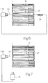
- optical device 1, 26 is associated with a position detector consisting, in the Figure 6 case, of a fixed rear detector 34 for detecting the distance between itself and the end of cigarette 3 opposite portion 2, and, in the Figure 7 case, of a lateral detector 35 for detecting the position of the plane of edge 15 of cigarette 3.
- the signal emitted by detector 34, 35 is sent to block 20 (or blocks 20) of device 1 (or devices 26) to permit block 20 (or blocks 20) to emit a signal corrected according to the distance between the plane of edge 15 of cigarette 3 and plane 10.
- detector 34, 35 may be dispensed with by extending the observation range of sensor 17 to edge 15 and hence to the outer paper layer 36 of cigarette 3, and by processing brightness curve 37, supplied by sensor 17, differently as compared with Figure 1.
- the curve 37 signal is sent to differentiating block 19 and hence index generating block 20, as well as in parallel manner to a comparing block 38 which is supplied by a memory 39 with a signal relative to a correct brightness curve 40 ( Figure 8).
- curve 40 presents two peaks 41 relative to detection of paper layer 36. Since peaks 41 are relative to the detection of white points in plane 10, identical peaks 41 should be present in any curve 37 relative to a cigarette 3 whose edge 15 lies in plane 10. If they are not, this means edge 15 is shifted in relation to plane 10 by an amount the value of which is indicated by an output signal of block 38; which output signal is used to drive a variable-gain amplifier 42 interposed between the output of block 20 and the input of block 21, for supplying block 21 with a modified contrast index to eliminate the error due to the shift in edge 15 in relation to plane 10.
Abstract
Description
- The present invention relates to a cigarette filling optical control method.
- More specifically, the present invention relates to a method of controlling the conformation of the open end of cigarettes and, in particular, the presence or absence of tobacco at the open end, on a cigarette manufacturing machine and/or filter assembly machine and/or packing machine.
- At the output of a cigarette manufacturing machine and/or filter assembly machine and/or at the input of a packing machine, the cigarettes are normally subjected to numerous checks comprising a check of the filling to determine the presence or absence of tobacco at the open end of the cigarettes.
- In most cases, filling control consists in illuminating the front surface of the open end of the cigarette by means of a light source; forming an image of the front surface by means of a detecting unit featuring a telecamera or equivalent optical monitoring system; and transmitting the image to a comparing unit for comparing it with a specimen image and emitting a reject signal in the event the detected and specimen images differ over and above a given limit.
- In general, the difference in the detected and specimen images depends on differences in shading which, as is known, varies according to the presence of gaps on the front surface due to the absence of tobacco. Unfortunately, the shading of the detected image has been found to depend largely, not only on the presence of gaps, but also on the colour of the tobacco employed, so that known devices of the above type involve expensive, time-consuming setup procedures whenever the type of tobacco is changed.
- It is an object of the present invention to provide a straightforward, low-cost optical control method designed to overcome the aforementioned drawbacks.
- According to the present invention, there is provided a cigarette filling optical control method, characterized in that it comprises stages consisting in detecting at least one brightness curve of at least one part of the open end of the cigarette under observation; processing the brightness curve to obtain an index, preferably a contrast index; and comparing the resulting index with an equivalent given index to obtain a signal indicating acceptance of the cigarette under observation.
- The brightness curve is preferably processed by means of a differentiating block, the output signal of which, corresponding to a contrast curve, is further processed to obtain said contrast index.
- According to a preferred embodiment of the above method, the brightness curve is detected by means of an optical device presenting a reference plane consisting of a fixed plane for focusing the optical system itself; the method preferably comprising a further stage for mechanically or electrically controlling the position of the cigarette under observation in relation to the reference plane.
- A non-limiting embodiment of the present invention will be described by way of example with reference to the accompanying drawings, in which:
- Figure 1 shows a preferred embodiment of the optical device according to the present invention;
- Figure 2 shows a partial view of the Figure 1 device in two different operating situations;
- Figure 3 shows a working diagram of a brightness curve detected by means of the Figure 1 optical device;
- Figure 4 shows a further working diagram of the contrast index curve formed by processing the Figure 3 curve;
- Figure 5 shows a schematic view of a variation of the Figure 1 optical device;
- Figures 6 and 7 show schematic views of a first and second perfected embodiment of the optical devices in Figures 1 and 5;
- Figure 8 shows a working diagram of an alternative brightness curve detected by means of the Figure 1 optical device;
- Figure 9 shows a variation of a portion of Figure 1, relative to an optical device employing the Figure 8 brightness curve.
-
Number 1 in Figure 1 indicates an optical device for controlling the filling of theopen end portion 2 of acigarette 3. -
Device 1 comprises alight source 4 for emitting abeam 5 impinging on and illuminating thefront end surface 6 ofportion 2; and abiconvex lens 7 presenting anoptical axis 8 and afixed focus 9. As shown in Figure 2,device 1 presents a reference plane consisting of a fixed focusingplane 10 a given distance A fromlens 7, and a substantially zero depth of field. - As shown in Figure 1,
cigarette 3 is preferably, but not necessarily, engaged by amechanical guide device 11 defined by a front andrear wall plane 10, and along which eachcigarette 3 is fed transversely by a known conveyor device (not shown) into a control position coaxial withaxis 8.Wall 12 is made of transparent material with an inner surface coincident withplane 10; andwall 13 is separated fromwall 12 by a distance approximately equal to but no less than the length ofcigarette 3, and presents a lead-inportion 14 for exerting axial thrust oncigarette 3, as this is fed into said control position, so that the annularfront end edge 15 defined by the wrapping paper ofcigarette 3 is positioned tangent to plane 10. -
Lens 7 forms part of a detectingdevice 16 which also comprises asensor 17 located alongaxis 8, on the opposite side offocus 9 tolens 7, on the opposite side oflens 7 tocigarette 3, and at a given distance B (Figure 2) fromlens 7, for supplying in known manner a brightness curve 18 (Figure 3) relative to at least part of the image ofsurface 6 observed throughlens 7.Sensor 17 may consist of a CCD sensor, or one or more linear sensors for analyzing fixed linear portions of tobacco-filledsurface 6, i.e. the surface withinedge 15. -
Device 1 also comprises a known differentiatingblock 19 forprocessing curve 18 to obtain a contrast curve (not shown) which is in turn processed by a knownindex generating block 20 to obtain a contrast index of the image observed bysensor 17. In a knowncomparing block 21, the resulting contrast index is compared with a reference index (e.g. the mean contrast index of the last 1000cigarettes 3 examined) supplied toblock 21 by anemitter 22, to obtain a signal which is sent to athreshold circuit 23 for emitting a reject signal in the event the contrast index ofcigarette 3 and said reference index differ by an amount greater than a predetermined value. - In actual use - and with reference to the Figure 4
curve 24 showing the variation in the contrast index alongside a variation in the distance ofsurface 6 from focusing plane 10 - whenend portion 2 is completely and properly flat,i.e. surface 6 is a flat surface coplanar withedge 15 and plane 10 (Figure 2a),block 20 emits a signal corresponding to a maximum value D of the contrast index. The same does not apply, however, in theevent portion 2 presents gaps (Figure 2b) so thatsurface 6 is no longer coplanar withedge 15 andplane 10. In this case, in fact, asdevice 1 presents a substantially zero depth of field, the signals emitted byblock 20, and indicating the value of the contrast index, indicate a reduction in the contrast index (curve 24) in direct proportion to the distance betweensurface 6 andplane 10. If C is the reference index value,circuit 23 emits a reject signal when the difference between value C and the detected value E exceeds a given value. - In the Figure 5 variation, the
beam 5 emitted bysource 4 and reflected bysurface 6 is directed onto asemireflecting mirror 25 which reflects a first portion ofbeam 5 to form abeam 5a directed towards a first optical device 26a, and lets through a second portion ofbeam 5 to define abeam 5b which is directed by a fully reflectingmirror 27 towards a second optical device 26b. -
Optical devices 26 are substantially similar todevice 1, and comprise respective focusinglenses lens 7 and having respective fixed focusingplanes reference plane 10.Plane 10, which defines the correct plane ofedge 15 ofcigarette 3, may therefore be said to be equally out of focus in relation tolenses - Like
device 1, devices 26a, 26b compriserespective sensors 17, respective differentiatingblocks 19, and respective contrastindex generating blocks 20, the output signals of which are supplied to acomparing block 29. The output signal ofblock 29 presents a value depending on the difference between said two indexes, and is supplied to athreshold circuit 30 for emitting a reject signal when said output signal exceeds a given value. That is, ifsurface 6 is substantially coplanar withedge 15 and hence withplane 10, the two output signals fromblocks 20 cancel each other out, whereas the output signal fromblock 29 increases in proportion to the amount by whichsurface 6 is shifted, in relation toplane 10, towards one or other ofplanes - The signals supplied by
devices front edge 15 ofcigarette 3 does in fact lie inplane 10, which is definitely assured if provision is made formechanical guide device 11, as is normally the case on a packing machine, or for other means of maintainingcigarette 3 in the correct observation position described above. In some cases, however,cigarettes 3 fail to assume the correct observation position and are shifted axially in relation to it by varying amounts. - Such, for example, is the case shown in Figures 6 and 7 wherein
cigarettes 3 are retained by suction, in varying axial positions, insiderespective seats 31 on the outer periphery of afeed roller 32, e.g. of a filter assembly machine, and are fed successively byroller 32 through acontrol station 33 equipped with anoptical control device optical device rear detector 34 for detecting the distance between itself and the end ofcigarette 3opposite portion 2, and, in the Figure 7 case, of alateral detector 35 for detecting the position of the plane ofedge 15 ofcigarette 3. The signal emitted bydetector edge 15 ofcigarette 3 andplane 10. - As shown in Figure 8,
detector sensor 17 toedge 15 and hence to theouter paper layer 36 ofcigarette 3, and byprocessing brightness curve 37, supplied bysensor 17, differently as compared with Figure 1. - More specifically, and with reference to Figure 9, the
curve 37 signal is sent to differentiatingblock 19 and henceindex generating block 20, as well as in parallel manner to a comparingblock 38 which is supplied by amemory 39 with a signal relative to a correct brightness curve 40 (Figure 8). - At the points at which the observation line intersects
edge 15,curve 40 presents twopeaks 41 relative to detection ofpaper layer 36. Sincepeaks 41 are relative to the detection of white points inplane 10,identical peaks 41 should be present in anycurve 37 relative to acigarette 3 whoseedge 15 lies inplane 10. If they are not, this meansedge 15 is shifted in relation toplane 10 by an amount the value of which is indicated by an output signal ofblock 38; which output signal is used to drive a variable-gain amplifier 42 interposed between the output ofblock 20 and the input ofblock 21, for supplyingblock 21 with a modified contrast index to eliminate the error due to the shift inedge 15 in relation toplane 10.
Claims (14)
- A cigarette filling optical control method, characterized in that it comprises stages consisting in detecting at least one brightness curve (18; 37) of at least one part of the open end (2) of the cigarette (3) under observation; processing the brightness curve (18; 37) to obtain an index; and comparing the resulting index with an equivalent given index to obtain a signal indicating acceptance of the cigarette (3) under observation.
- A method as claimed in Claim 1, characterized in that said index is a contrast index.
- A method as claimed in Claim 2, characterized in that said brightness curve (18; 37) is processed by means of a differentiating block (19), the output signal of which, corresponding to a contrast curve, is further processed to obtain said contrast index.
- A method as claimed in any one of the foregoing Claims, characterized in that said brightness curve (18; 37) is detected by means of an optical device (1) presenting a reference plane consisting of a fixed focusing plane (10) of the optical device (1).
- A method as claimed in Claim 4, characterized in that said brightness curve (18; 37) is supplied by a sensor (17) of said optical device (1); the sensor (17) receiving a light beam (5) reflected by said open end (2) of the cigarette (3) and focused by a fixed-focus lens (7) presenting said fixed focusing plane (10) and a substantially zero depth of field.
- A method as claimed in Claim 1, 2 or 3, characterized in that it provides for detecting two brightness curves (18; 37) by means of two optical devices (26) presenting respective fixed focusing planes (10a, 10b) arranged symmetrically in relation to a reference plane (10).
- A method as claimed in Claim 6, characterized in that said brightness curves (18; 37) are supplied by respective sensors (17) of the respective optical devices (26); each sensor (17) receiving a respective portion (5a, 5b) of a light beam (5) which is reflected by said open end (2) of the cigarette (3); each said beam portion (5a, 5b) being focused by a respective fixed-focus lens (28a; 28b); each optical device (26) presenting a respective said fixed focusing plane (10) and a substantially zero depth of field; and said indexes of said optical devices (26) being compared with each other.
- A method as claimed in any one of the foregoing Claims from 4 to 7, characterized in that it comprises a further stage consisting in controlling the position of the cigarette (3) under observation in relation to the reference plane.
- A method as claimed in Claim 8, characterized in that said further control stage in turn comprises a stage consisting in acting, via mechanical means (11), on the cigarette (3) under observation, so that its end (2) is positioned in the reference plane (10).
- A method as claimed in Claim 8, characterized in that said further control stage in turn comprises a stage consisting in detecting the position of the cigarette (3) under observation in relation to said reference plane (10).
- A method as claimed in Claim 10, characterized in that it comprises yet a further stage consisting in modifying the value of said index as a function of the position of the cigarette (3) under observation in relation to said reference plane (10).
- A method as claimed in Claim 10 or 11, characterized in that the position of the cigarette (3) under observation in relation to the reference plane (10) is detected via electronic sensor means (34; 35).
- A method as claimed in Claim 10 or 11, characterized in that the position of the cigarette (3) under observation in relation to the reference plane (10) is detected by extending observation of the open end (2) of the cigarette (3) to a layer (36) of peripheral paper, to obtain a brightness curve (37) presenting two peaks (41) at said layer (36), and by comparing these two peaks (41) with the peaks of a reference curve (40).
- A method as claimed in any one of the foregoing Claims, characterized in that it also comprises stages consisting in comparing said contrast index with a reference index; and emitting a reject signal in the event the contrast index differs from the reference index by an amount over and above a predetermined value.
Applications Claiming Priority (2)
| Application Number | Priority Date | Filing Date | Title |
|---|---|---|---|
| ITBO930297 | 1993-06-28 | ||
| ITBO930297A IT1263446B (en) | 1993-06-28 | 1993-06-28 | OPTICAL CONTROL METHOD FOR CIGARETTE FILLING. |
Publications (4)
| Publication Number | Publication Date |
|---|---|
| EP0630586A2 true EP0630586A2 (en) | 1994-12-28 |
| EP0630586A3 EP0630586A3 (en) | 1996-06-26 |
| EP0630586B1 EP0630586B1 (en) | 1999-11-17 |
| EP0630586B2 EP0630586B2 (en) | 2004-01-02 |
Family
ID=11339154
Family Applications (1)
| Application Number | Title | Priority Date | Filing Date |
|---|---|---|---|
| EP94109820A Expired - Lifetime EP0630586B2 (en) | 1993-06-28 | 1994-06-24 | Cigarette filling optical control method |
Country Status (4)
| Country | Link |
|---|---|
| US (1) | US5596187A (en) |
| EP (1) | EP0630586B2 (en) |
| DE (1) | DE69421643T3 (en) |
| IT (1) | IT1263446B (en) |
Cited By (8)
| Publication number | Priority date | Publication date | Assignee | Title |
|---|---|---|---|---|
| EP0843974A3 (en) * | 1996-11-20 | 1999-06-16 | SASIB TOBACCO S.p.A. | Method and device for inspecting without direct contact the ends of cigarettes, or similar |
| DE19921725A1 (en) * | 1999-05-12 | 2000-11-16 | Focke & Co | Quality control of cigarettes to ensure that they are completely filled with tobacco has arrangement of light bands projected on their ends with reflected light band separation used to determine correct filling |
| DE19921721A1 (en) * | 1999-05-12 | 2000-11-16 | Focke & Co | Method and device for checking cigarette heads |
| US6169600B1 (en) | 1998-11-20 | 2001-01-02 | Acuity Imaging, Llc | Cylindrical object surface inspection system |
| EP1176092A1 (en) * | 2000-07-28 | 2002-01-30 | Focke & Co. (GmbH & Co.) | Method and apparatus for inspecting cigarette ends |
| WO2003055338A2 (en) * | 2001-12-27 | 2003-07-10 | Hauni Maschinenbau Ag | Device and system for measuring the properties of multi-segmented filters and corresponding method |
| WO2017182362A1 (en) * | 2016-04-19 | 2017-10-26 | Hauni Maschinenbau Gmbh | Assembly and method for optically inspecting rod-shaped articles of the tobacco-processing industry |
| EP3042574B1 (en) | 2015-01-09 | 2018-10-10 | Hauni Maschinenbau GmbH | Device and method for frontal inspection of a transversally conveyed rod-shaped article in a machine for the tobacco processing industry |
Families Citing this family (12)
| Publication number | Priority date | Publication date | Assignee | Title |
|---|---|---|---|---|
| IT1286264B1 (en) * | 1996-10-18 | 1998-07-08 | Gd Spa | METHOD OF CHECKING THE DEGREE OF FILLING OF THE ENDS OF SMOKING ARTICLES |
| EP0875771B1 (en) * | 1997-04-30 | 2004-07-14 | Sick Ag | Opto-electronic sensor with multiple photosensitive elements arranged in a row or array |
| DE19718389A1 (en) * | 1997-04-30 | 1998-11-05 | Sick Ag | Optoelectronic sensor device for monitoring surveillance zone |
| US7076387B2 (en) * | 2003-12-15 | 2006-07-11 | Texas Instruments Incorporated | Method for determining the equivalency index of products and processes |
| DE102004040912A1 (en) * | 2004-08-23 | 2006-03-09 | Hauni Maschinenbau Ag | Optical control of tobacco industry products |
| DE102012203579B3 (en) | 2012-03-07 | 2013-06-06 | Hauni Maschinenbau Ag | Measuring device and measuring method for determining a measured variable at one end of a rod-shaped product of the tobacco processing industry |
| DE102012210037A1 (en) | 2012-06-14 | 2013-12-19 | Hauni Maschinenbau Ag | Measuring device and method for optical inspection of an end face of a cross-axially conveyed rod-shaped product of the tobacco processing industry |
| DE102012210031A1 (en) * | 2012-06-14 | 2013-12-19 | Hauni Maschinenbau Ag | Apparatus and method for evaluating an end face of a rod-shaped product of the tobacco processing industry |
| CN102818769B (en) * | 2012-09-05 | 2015-04-22 | 江苏中烟工业有限责任公司 | Method for evaluating mixing uniformity of tobacco shreds in finished product cigarette |
| CN103105449B (en) * | 2013-02-18 | 2014-12-24 | 江苏中烟工业有限责任公司 | Method for evaluating cigarette filament charging uniformity based on characteristic fragrance substance |
| US9844232B2 (en) * | 2014-03-11 | 2017-12-19 | R.J. Reynolds Tobacco Company | Smoking article inspection system and associated method |
| PL3475687T3 (en) * | 2016-06-22 | 2022-03-28 | G.D S.P.A. | A transferring and inspecting unit of a group of elongated elements |
Citations (9)
| Publication number | Priority date | Publication date | Assignee | Title |
|---|---|---|---|---|
| GB1112687A (en) * | 1965-03-12 | 1968-05-08 | Schmermund Alfred | Improvements in or relating to arrangements for testing blocks of cigarettes |
| US3812349A (en) * | 1973-04-06 | 1974-05-21 | Laser Sciences Inc | Apparatus for inspecting cigarettes or the like |
| FR2312975A1 (en) * | 1975-06-03 | 1976-12-31 | Amf Inc | METHOD AND DEVICE FOR THE OPTICAL INSPECTION OF THE ENDS OF CIGARETTES |
| GB2176598A (en) * | 1985-06-11 | 1986-12-31 | Koerber Ag | Method and apparatus for optically testing the ends of rod-shaped articles of the tobacco processing industry |
| EP0370231A1 (en) * | 1988-11-25 | 1990-05-30 | SASIB S.p.A. | Optical device for checking the cigarette tips |
| DE4000658A1 (en) * | 1989-01-13 | 1990-08-09 | Gd Spa | TESTING SYSTEM FOR THE END OF CIGARETTE GROUPS |
| US5013905A (en) * | 1988-05-31 | 1991-05-07 | G.D Societa' Per Azioni | Method of electro-optically inspecting cigarettes |
| US5107337A (en) † | 1990-07-24 | 1992-04-21 | Matsushita Electric Industrial Co., Ltd. | Automatic focusing apparatus of video camera |
| EP0585686A1 (en) * | 1992-09-03 | 1994-03-09 | G.D Societa' Per Azioni | Optical cigarette filling control device |
Family Cites Families (3)
| Publication number | Priority date | Publication date | Assignee | Title |
|---|---|---|---|---|
| IT1010706B (en) * | 1974-03-22 | 1977-01-20 | Amf Sasib | PROCEDURE AND DEVICE FOR THE OPTICAL CHECK OF THE FILLING DEGREE OF THE CIGARETTE HEADS |
| US5223915A (en) * | 1989-01-13 | 1993-06-29 | G.D. Societa' Per Azioni | Cigarette end group inspection system |
| US5235649A (en) * | 1991-06-13 | 1993-08-10 | Videk Corporation | Cigarette inspection method |
-
1993
- 1993-06-28 IT ITBO930297A patent/IT1263446B/en active IP Right Grant
-
1994
- 1994-06-24 EP EP94109820A patent/EP0630586B2/en not_active Expired - Lifetime
- 1994-06-24 DE DE69421643T patent/DE69421643T3/en not_active Expired - Lifetime
- 1994-06-27 US US08/266,176 patent/US5596187A/en not_active Expired - Lifetime
Patent Citations (9)
| Publication number | Priority date | Publication date | Assignee | Title |
|---|---|---|---|---|
| GB1112687A (en) * | 1965-03-12 | 1968-05-08 | Schmermund Alfred | Improvements in or relating to arrangements for testing blocks of cigarettes |
| US3812349A (en) * | 1973-04-06 | 1974-05-21 | Laser Sciences Inc | Apparatus for inspecting cigarettes or the like |
| FR2312975A1 (en) * | 1975-06-03 | 1976-12-31 | Amf Inc | METHOD AND DEVICE FOR THE OPTICAL INSPECTION OF THE ENDS OF CIGARETTES |
| GB2176598A (en) * | 1985-06-11 | 1986-12-31 | Koerber Ag | Method and apparatus for optically testing the ends of rod-shaped articles of the tobacco processing industry |
| US5013905A (en) * | 1988-05-31 | 1991-05-07 | G.D Societa' Per Azioni | Method of electro-optically inspecting cigarettes |
| EP0370231A1 (en) * | 1988-11-25 | 1990-05-30 | SASIB S.p.A. | Optical device for checking the cigarette tips |
| DE4000658A1 (en) * | 1989-01-13 | 1990-08-09 | Gd Spa | TESTING SYSTEM FOR THE END OF CIGARETTE GROUPS |
| US5107337A (en) † | 1990-07-24 | 1992-04-21 | Matsushita Electric Industrial Co., Ltd. | Automatic focusing apparatus of video camera |
| EP0585686A1 (en) * | 1992-09-03 | 1994-03-09 | G.D Societa' Per Azioni | Optical cigarette filling control device |
Cited By (12)
| Publication number | Priority date | Publication date | Assignee | Title |
|---|---|---|---|---|
| EP0843974A3 (en) * | 1996-11-20 | 1999-06-16 | SASIB TOBACCO S.p.A. | Method and device for inspecting without direct contact the ends of cigarettes, or similar |
| US6169600B1 (en) | 1998-11-20 | 2001-01-02 | Acuity Imaging, Llc | Cylindrical object surface inspection system |
| DE19921725A1 (en) * | 1999-05-12 | 2000-11-16 | Focke & Co | Quality control of cigarettes to ensure that they are completely filled with tobacco has arrangement of light bands projected on their ends with reflected light band separation used to determine correct filling |
| DE19921721A1 (en) * | 1999-05-12 | 2000-11-16 | Focke & Co | Method and device for checking cigarette heads |
| US6407807B1 (en) | 1999-05-12 | 2002-06-18 | Focke & Co. (Gmbh & Co.) | Method and apparatus for testing cigarette heads |
| US6437317B1 (en) | 1999-05-12 | 2002-08-20 | Focke & Co. (Gmbh & Co.) | Method and apparatus for inspecting cigarette heads |
| EP1176092A1 (en) * | 2000-07-28 | 2002-01-30 | Focke & Co. (GmbH & Co.) | Method and apparatus for inspecting cigarette ends |
| WO2003055338A2 (en) * | 2001-12-27 | 2003-07-10 | Hauni Maschinenbau Ag | Device and system for measuring the properties of multi-segmented filters and corresponding method |
| WO2003055338A3 (en) * | 2001-12-27 | 2004-03-25 | Hauni Maschinenbau Ag | Device and system for measuring the properties of multi-segmented filters and corresponding method |
| EP3042574B1 (en) | 2015-01-09 | 2018-10-10 | Hauni Maschinenbau GmbH | Device and method for frontal inspection of a transversally conveyed rod-shaped article in a machine for the tobacco processing industry |
| EP3042574B2 (en) † | 2015-01-09 | 2022-06-01 | Hauni Maschinenbau GmbH | Device and method for frontal inspection of a transversally conveyed rod-shaped article in a machine for the tobacco processing industry |
| WO2017182362A1 (en) * | 2016-04-19 | 2017-10-26 | Hauni Maschinenbau Gmbh | Assembly and method for optically inspecting rod-shaped articles of the tobacco-processing industry |
Also Published As
| Publication number | Publication date |
|---|---|
| IT1263446B (en) | 1996-08-05 |
| EP0630586B1 (en) | 1999-11-17 |
| ITBO930297A0 (en) | 1993-06-28 |
| EP0630586A3 (en) | 1996-06-26 |
| DE69421643T2 (en) | 2000-06-21 |
| US5596187A (en) | 1997-01-21 |
| EP0630586B2 (en) | 2004-01-02 |
| DE69421643T3 (en) | 2004-08-05 |
| ITBO930297A1 (en) | 1994-12-28 |
| DE69421643D1 (en) | 1999-12-23 |
Similar Documents
| Publication | Publication Date | Title |
|---|---|---|
| EP0630586A2 (en) | Cigarette filling optical control method | |
| US20050163363A1 (en) | Continuous filter rod testing | |
| US20070091326A1 (en) | Device and method for measuring properties of multi-segment filters or combinations of filter segments | |
| US5264700A (en) | Method for telecamera-checking products wrapped with transparent material | |
| EP1830179B1 (en) | A method and apparatus for determining one or more physical properties of a rolled smoking article or filter rod | |
| EP0570163B1 (en) | Apparatus and Method for optically inspecting cylindrical surfaces | |
| US5371584A (en) | Apparatus for the detection of contaminants in an elongated textile product | |
| JP2005512586A (en) | Apparatus and system for measuring the characteristics of a multi-segment filter and method for this measurement | |
| US20070137661A1 (en) | Optical monitoring of products of the tobacco-processing industry | |
| EP0585686B1 (en) | Optical cigarette filling control device | |
| JPS6037968A (en) | Method and apparatus for scanning rod shaped article in tobacco processing industry | |
| EP0634112A2 (en) | Cigarette filling optical control method and device | |
| US5406376A (en) | Apparatus for testing end portions of rod-shaped articles of the tobacco processing industry | |
| US5932888A (en) | Web or sheet edge position measurement process and device | |
| US20100118314A1 (en) | Determining track origin | |
| EP0848246B1 (en) | Method of measuring the intensity of radiation transmitted through a body | |
| EP0370231A1 (en) | Optical device for checking the cigarette tips | |
| JP3730082B2 (en) | Cigarette inspection device | |
| EP0653170A1 (en) | A device for inspecting filter end face of manufactured filter cigarette | |
| CN106063586B (en) | Rod-forming machine for the tobacco processing industry and method for producing a multi-segment rod | |
| WO1996034273A1 (en) | A method and a device for optical monitoring of at least one series of strings, especially from glue | |
| US5978079A (en) | Method of controlling the endfill of tobacco articles | |
| US6882768B2 (en) | Optical spacer switch and insertion head, automatic insertion machine and method for inserting components on substrates by using the optical spacer switch | |
| DE69421643T9 (en) | OPTICAL TEST DEVICE FOR FILLING CIGARETTES | |
| EP3714707A1 (en) | A measuring system for controlling a quality of a tube and a method for controlling a quality of a tube |
Legal Events
| Date | Code | Title | Description |
|---|---|---|---|
| PUAI | Public reference made under article 153(3) epc to a published international application that has entered the european phase |
Free format text: ORIGINAL CODE: 0009012 |
|
| AK | Designated contracting states |
Kind code of ref document: A2 Designated state(s): DE FR GB IT |
|
| PUAL | Search report despatched |
Free format text: ORIGINAL CODE: 0009013 |
|
| AK | Designated contracting states |
Kind code of ref document: A3 Designated state(s): DE FR GB IT |
|
| 17P | Request for examination filed |
Effective date: 19961213 |
|
| 17Q | First examination report despatched |
Effective date: 19981208 |
|
| GRAG | Despatch of communication of intention to grant |
Free format text: ORIGINAL CODE: EPIDOS AGRA |
|
| GRAG | Despatch of communication of intention to grant |
Free format text: ORIGINAL CODE: EPIDOS AGRA |
|
| GRAH | Despatch of communication of intention to grant a patent |
Free format text: ORIGINAL CODE: EPIDOS IGRA |
|
| GRAH | Despatch of communication of intention to grant a patent |
Free format text: ORIGINAL CODE: EPIDOS IGRA |
|
| GRAA | (expected) grant |
Free format text: ORIGINAL CODE: 0009210 |
|
| AK | Designated contracting states |
Kind code of ref document: B1 Designated state(s): DE FR GB IT |
|
| REF | Corresponds to: |
Ref document number: 69421643 Country of ref document: DE Date of ref document: 19991223 |
|
| ITF | It: translation for a ep patent filed |
Owner name: STUDIO TORTA S.R.L. |
|
| ET | Fr: translation filed | ||
| PLBQ | Unpublished change to opponent data |
Free format text: ORIGINAL CODE: EPIDOS OPPO |
|
| PLBI | Opposition filed |
Free format text: ORIGINAL CODE: 0009260 |
|
| PLBF | Reply of patent proprietor to notice(s) of opposition |
Free format text: ORIGINAL CODE: EPIDOS OBSO |
|
| 26 | Opposition filed |
Opponent name: FOCKE & CO. (GMBH & CO.) Effective date: 20000817 |
|
| PLBF | Reply of patent proprietor to notice(s) of opposition |
Free format text: ORIGINAL CODE: EPIDOS OBSO |
|
| PLBF | Reply of patent proprietor to notice(s) of opposition |
Free format text: ORIGINAL CODE: EPIDOS OBSO |
|
| REG | Reference to a national code |
Ref country code: GB Ref legal event code: IF02 |
|
| PLAW | Interlocutory decision in opposition |
Free format text: ORIGINAL CODE: EPIDOS IDOP |
|
| PLAW | Interlocutory decision in opposition |
Free format text: ORIGINAL CODE: EPIDOS IDOP |
|
| PLAW | Interlocutory decision in opposition |
Free format text: ORIGINAL CODE: EPIDOS IDOP |
|
| RAP2 | Party data changed (patent owner data changed or rights of a patent transferred) |
Owner name: G.D SOCIETA' PER AZIONI |
|
| PUAH | Patent maintained in amended form |
Free format text: ORIGINAL CODE: 0009272 |
|
| STAA | Information on the status of an ep patent application or granted ep patent |
Free format text: STATUS: PATENT MAINTAINED AS AMENDED |
|
| 27A | Patent maintained in amended form |
Effective date: 20040102 |
|
| AK | Designated contracting states |
Kind code of ref document: B2 Designated state(s): DE FR GB IT |
|
| ET3 | Fr: translation filed ** decision concerning opposition | ||
| PGFP | Annual fee paid to national office [announced via postgrant information from national office to epo] |
Ref country code: GB Payment date: 20070628 Year of fee payment: 14 |
|
| PGFP | Annual fee paid to national office [announced via postgrant information from national office to epo] |
Ref country code: IT Payment date: 20070628 Year of fee payment: 14 |
|
| PGFP | Annual fee paid to national office [announced via postgrant information from national office to epo] |
Ref country code: FR Payment date: 20070618 Year of fee payment: 14 |
|
| GBPC | Gb: european patent ceased through non-payment of renewal fee |
Effective date: 20080624 |
|
| REG | Reference to a national code |
Ref country code: FR Ref legal event code: ST Effective date: 20090228 |
|
| PG25 | Lapsed in a contracting state [announced via postgrant information from national office to epo] |
Ref country code: GB Free format text: LAPSE BECAUSE OF NON-PAYMENT OF DUE FEES Effective date: 20080624 |
|
| PG25 | Lapsed in a contracting state [announced via postgrant information from national office to epo] |
Ref country code: IT Free format text: LAPSE BECAUSE OF NON-PAYMENT OF DUE FEES Effective date: 20080624 Ref country code: FR Free format text: LAPSE BECAUSE OF NON-PAYMENT OF DUE FEES Effective date: 20080630 |
|
| PGFP | Annual fee paid to national office [announced via postgrant information from national office to epo] |
Ref country code: DE Payment date: 20110629 Year of fee payment: 18 |
|
| PG25 | Lapsed in a contracting state [announced via postgrant information from national office to epo] |
Ref country code: DE Free format text: LAPSE BECAUSE OF NON-PAYMENT OF DUE FEES Effective date: 20130101 |
|
| REG | Reference to a national code |
Ref country code: DE Ref legal event code: R119 Ref document number: 69421643 Country of ref document: DE Effective date: 20130101 |