EP0629880A1 - Entfernungsmesser - Google Patents
Entfernungsmesser Download PDFInfo
- Publication number
- EP0629880A1 EP0629880A1 EP94401292A EP94401292A EP0629880A1 EP 0629880 A1 EP0629880 A1 EP 0629880A1 EP 94401292 A EP94401292 A EP 94401292A EP 94401292 A EP94401292 A EP 94401292A EP 0629880 A1 EP0629880 A1 EP 0629880A1
- Authority
- EP
- European Patent Office
- Prior art keywords
- frequency
- rangefinder
- rangefinder according
- target
- frequencies
- Prior art date
- Legal status (The legal status is an assumption and is not a legal conclusion. Google has not performed a legal analysis and makes no representation as to the accuracy of the status listed.)
- Withdrawn
Links
- 230000010363 phase shift Effects 0.000 claims abstract description 46
- 238000005259 measurement Methods 0.000 claims abstract description 44
- 230000004907 flux Effects 0.000 claims abstract description 24
- 238000004364 calculation method Methods 0.000 claims description 25
- 108091008695 photoreceptors Proteins 0.000 claims description 24
- 239000013307 optical fiber Substances 0.000 claims description 11
- 238000012545 processing Methods 0.000 claims description 9
- 230000003287 optical effect Effects 0.000 claims description 7
- 230000000737 periodic effect Effects 0.000 claims description 4
- 230000003321 amplification Effects 0.000 claims description 3
- 230000000295 complement effect Effects 0.000 claims description 3
- 238000003199 nucleic acid amplification method Methods 0.000 claims description 3
- 230000010287 polarization Effects 0.000 claims description 3
- 238000000926 separation method Methods 0.000 claims description 2
- 238000001514 detection method Methods 0.000 description 4
- 239000000835 fiber Substances 0.000 description 4
- 230000006870 function Effects 0.000 description 4
- 238000010586 diagram Methods 0.000 description 3
- 230000008447 perception Effects 0.000 description 3
- 210000001747 pupil Anatomy 0.000 description 3
- 230000001360 synchronised effect Effects 0.000 description 3
- 230000035559 beat frequency Effects 0.000 description 2
- 238000012937 correction Methods 0.000 description 2
- 238000000034 method Methods 0.000 description 2
- 238000012544 monitoring process Methods 0.000 description 2
- 230000002093 peripheral effect Effects 0.000 description 2
- 239000000725 suspension Substances 0.000 description 2
- 230000007704 transition Effects 0.000 description 2
- 238000012800 visualization Methods 0.000 description 2
- 239000011324 bead Substances 0.000 description 1
- 230000005540 biological transmission Effects 0.000 description 1
- 230000008859 change Effects 0.000 description 1
- 239000003086 colorant Substances 0.000 description 1
- 230000002860 competitive effect Effects 0.000 description 1
- 230000003247 decreasing effect Effects 0.000 description 1
- 238000006073 displacement reaction Methods 0.000 description 1
- 230000000694 effects Effects 0.000 description 1
- 210000000887 face Anatomy 0.000 description 1
- 238000003384 imaging method Methods 0.000 description 1
- 239000000463 material Substances 0.000 description 1
- 238000003032 molecular docking Methods 0.000 description 1
- 230000003071 parasitic effect Effects 0.000 description 1
- 239000011505 plaster Substances 0.000 description 1
- 238000010408 sweeping Methods 0.000 description 1
- 238000012546 transfer Methods 0.000 description 1
- 230000001960 triggered effect Effects 0.000 description 1
Images


Classifications
-
- G—PHYSICS
- G01—MEASURING; TESTING
- G01S—RADIO DIRECTION-FINDING; RADIO NAVIGATION; DETERMINING DISTANCE OR VELOCITY BY USE OF RADIO WAVES; LOCATING OR PRESENCE-DETECTING BY USE OF THE REFLECTION OR RERADIATION OF RADIO WAVES; ANALOGOUS ARRANGEMENTS USING OTHER WAVES
- G01S17/00—Systems using the reflection or reradiation of electromagnetic waves other than radio waves, e.g. lidar systems
- G01S17/02—Systems using the reflection of electromagnetic waves other than radio waves
- G01S17/06—Systems determining position data of a target
- G01S17/08—Systems determining position data of a target for measuring distance only
- G01S17/32—Systems determining position data of a target for measuring distance only using transmission of continuous waves, whether amplitude-, frequency-, or phase-modulated, or unmodulated
- G01S17/36—Systems determining position data of a target for measuring distance only using transmission of continuous waves, whether amplitude-, frequency-, or phase-modulated, or unmodulated with phase comparison between the received signal and the contemporaneously transmitted signal
Definitions
- the invention relates to a rangefinder, of the type in which the distance of a target is determined from the phase shift between a periodic signal transmitted to the target and the signal backscattered by the target.
- the intensity of the light beam emitted by a laser diode is modulated at high frequency.
- the modulated beam is transmitted by a collimating lens to angular deflection means which make it possible to scan a space area.
- the backscattered light flux is captured by a photoreceptor connected to a phasemeter and to calculation means to determine the phase shift between the emitted beam and the captured flux and to deduce therefrom the distances from the backscattering points of the observed area of space.
- the distances which are thus calculated can be transformed into shades of gray or false colors in accordance with a predetermined code, for viewing a rangefinder image or "distance" image of the area of space observed.
- the measurement of the phase shift between the transmitted signal and the received signal is made, not at the high modulation frequency, but at a much lower intermediate frequency, the transition to this intermediate frequency being done by heterodyning techniques well known to those skilled in the art.
- This range could be increased by decreasing the modulation frequency, but this would be to the detriment of the accuracy of the measurement.
- the subject of the invention is a rangefinder which is not subject to these drawbacks.
- the invention also relates to a rangefinder of the aforementioned type, having a range much greater than that of known competitive devices and capable of measure with precision and very great speed any distance between a value substantially zero and the maximum range.
- Another subject of the invention is a range finder of this type, which can provide images containing distance information from an observed area at each point, at a high rate close to the video rate.
- a rangefinder comprising at least one light source such as a laser diode, a collimation objective associated with the source for the emission of a light beam towards a target, means for periodic modulation of the intensity of the beam emitted at two different frequencies, means for receiving a light flux backscattered by the target, means for measuring the phase shifts between the emitted beam and the flux received at the two aforementioned frequencies, and calculation means for deduce the distance from the target, characterized in that the ratio of the two modulation frequencies is a power of 2 and in that the phase shift measurement and calculation means are of the wired digital type allowing simultaneous real-time measurement of phase shifts at the two aforementioned frequencies and the calculation in real time of the distance from the target.
- the aforementioned wired type circuits are for example EPLD (Erasable Programable Logical Devices) circuits.
- EPLD Erasable Programable Logical Devices
- the two modulation frequencies of the beam emitted towards the target are chosen according to the maximum range and the precision which it is desired to obtain.
- the maximum range of the rangefinder is approximately equal to half the wavelength corresponding to the lowest modulation frequency.
- the modulation frequencies are synchronous or locked in phase, that is to say that their sinusoidal variations pass by zero at simultaneous instants (more exactly, the passage by zero of the sinusoidal signal having the lowest frequency must be carried out at the same time as the zero crossing of the sine wave signal having the highest frequency) or else that the difference between the phase of the low frequency signal and of the phase modulo 2 ⁇ of the high frequency signal is a constant.
- the ratio of these frequencies can be between 2 and 1024, and for example is 8 or 16.
- the reception means comprise a photoreceptor, a frequency separation circuit connecting the output of the photoreceptor to two parallel processing channels also receiving as input sinusoidal reference signals having frequencies equal to the frequencies of above-mentioned modulation, these two channels each comprising a double heterodyne circuit for passing at the same intermediate frequency and a double digital pulse counting circuit, the outputs of these two channels being connected to the inputs of a computing circuit.
- phase shifts of the transmitted and received signals can be measured simultaneously and in real time, the measurement being made at the same intermediate frequency, much lower than the modulation frequencies, which also makes it possible to calculate the distance in real time using of a wired circuit, for example of the EPLD type as mentioned above.
- the rangefinder comprises a single laser diode and means for controlling and supplying this diode making it possible to modulate the beam emitted simultaneously at the two aforementioned frequencies, the modulation at the lowest frequency serving carrier at the highest frequency modulation.
- the range finder comprises two laser diodes each emitting a light beam, means for modulating one of these beams at one of the aforementioned frequencies, means for modulating the another of these beams at the above-mentioned other frequency, and means for optical multiplexing by polarization of the two modulated beams.
- the photoreceptor receiving the flux backscattered by the target has a small sensitive surface, the area of which corresponds substantially to that of the spot formed by the backscattered flux when the target is substantially at the maximum distance from measured.
- the rangefinder comprises means of angular deviation periodic of the emitted beam, allowing line scanning of an observation field, these means comprising for example pivoting mirrors with controlled and controlled galvanometric control.
- the range finder then makes it possible to scan a zone of space and obtain telemetric images of this zone of space at a relatively rapid rate, of the order of the video rate, this being made possible by the speed of the calculation distances.
- the rangefinder comprises a plurality of optical fibers whose first ends are located in the aforementioned field of observation in the vicinity of the angular deflection means, and whose second ends have orientations and a distribution predetermined with respect to the rangefinder.
- the range finder can also include means for processing the photoreceptor output signals, connected to display means for obtaining an image of the reflectance of the observed area. It is thus possible to simultaneously obtain a reflectance image, analogous to a video image, of the area observed in addition to a rangefinder image of this area.
- Figure 1 shows the essential components of a rangefinder according to the invention.
- This rangefinder comprises a light source such as a laser diode 10, associated with a collimating lens or objective 12 to emit a light beam 14 towards a target 16 located at a distance range of the rangefinder between zero and the maximum range of the rangefinder.
- a light source such as a laser diode 10
- a collimating lens or objective 12 to emit a light beam 14 towards a target 16 located at a distance range of the rangefinder between zero and the maximum range of the rangefinder.
- the laser diode 10 is powered and controlled by a set 18 of electronic circuits, which make it possible to modulate the intensity of the emitted beam 14 at two different frequencies, the lowest of which determines the maximum range of the rangefinder and the highest of which determines the accuracy of measurement.
- the range finder also includes a photoreceptor 20 associated with a focusing lens 22 and an interference filter 24 to receive the light flux backscattered by the target 16.
- the output of the photoreceptor 20 is connected to an input of the set of electronic circuits 18, the outputs of which can be connected to recording means 26 and to means 28 for using or applying the distance measurements carried out, for example propulsion or steering control means, display means, etc.
- the two modulation frequencies of the intensity of the light beams 14 emitted by the laser diode 10 are preferably obtained by dividing by 2 the same frequency, and their ratio is a power of 2.
- FIGS. 2a and 2b each represent a sinusoidal signal of frequency F, the signal 30 of FIG. 2a corresponding for example to the modulation at frequency F of the intensity of the beam 14 emitted in the direction of the target 16, while the signal 32 of FIG. 2b corresponds to the light flux backscattered by the target 16 and received by the photoreceptor 20, this signal 32 having, with respect to the signal 30, a phase shift ⁇ less than 2 ⁇ and which corresponds to the return path of the light between the rangefinder and the target, that is to say between the laser diode 10 and the photoreceptor 20.
- FIGS. 3a and 3b represent sinusoidal signals 34 and 36 having a frequency f equal to the product of a power of 2 and the aforementioned frequency F, the signal 34 of FIG. 3a representing the modulation at the frequency f of the intensity of the beam 14 emitted towards the target 16, while the signal 36 of FIG. 3b represents the modulation at this same frequency of the flux backscattered by the target 16 and received by the photoreceptor 20.
- the modulation signals at frequencies f and F are synchronous or locked in phase, the signal 30 passing through zero (or through an average value) at times when the signal 34 itself passes through zero (or through an average value).
- the real phase shift of signals 34 and 36 corresponds to the return path of light between the rangefinder and the target and is of course equal to the phase shift ⁇ between signals 30 and 32 at frequency F when the target is at the same distance in both cases.
- k is equal to 1, the frequency ratio being equal to 8.
- the distance from the target must remain less than half wavelength corresponding to the frequency F, this half-wavelength therefore defining the maximum range of the rangefinder. For example, if the frequency F is 1 MHz, the maximum range of the rangefinder is about 150 meters.
- FIG. 4 shows circuits for implementing this measurement principle.
- These circuits include a transmission module 38 for supplying and controlling the laser diode 10, this module 38 comprising means 40 and 42 generating the frequencies F and f respectively, and means 44 for polarizing the laser diode 10
- the means for generating frequencies F and f preferably comprise a high frequency oscillator, associated with dividers by two.
- the intensity of the light beam 14 emitted by the laser diode 10 is thus modulated at the frequency F, and this modulation is itself subjected to a modulation at the frequency f, the first modulation at the frequency F serving as a carrier for the modulation. at frequency f.
- the photoreceptor 20 on which the light flux backscattered by the target is focused is connected to a frequency separator 46, the two outputs of which are connected to two parallel processing channels, one receiving signals of frequency F and the other of signals of frequency f.
- Each processing channel successively comprises a module 48 for passing through an intermediate frequency and a wired digital circuit 50 for phase shift measurement, leading to a wired calculation circuit 52, common to both treatment routes.
- Each frequency change module 48 itself comprises two identical channels, one of which receives an output signal from the separator 46 and the other of which receives a reference signal at the same frequency, supplied by the corresponding means 40 or 42 of frequency generation.
- Each channel of a module 48 comprises a mixer 54, one input of which receives a signal at the frequency F or f and the other input of which receives a signal of frequency F'or f 'supplied by a local oscillator 56, the mixer 54 providing at the output a beat signal at the frequency FF 'or ff' respectively, which is applied to an input of the phase measurement circuit 50 via a bandpass filter 58 tuned to the beat frequency.
- the frequencies F 'and f' of the oscillators 56 are determined so that the beat frequencies F-F 'and f-f' are equal to the same intermediate frequency, for example 400 kHz.
- This passage from the modulation frequencies to the intermediate frequency does not modify the phase shifts between the reference signals and the output signals of the photoreceptor, so that the same phase shifts are found between channels at the input and at the output of a module 48.
- Each phase-shift measurement circuit 50 is of the high frequency clock pulse counting type, the counting starting at the opening of a door, triggered by the passage of the signal applied to one of the inputs of the circuit 50, and stopping when the door closes, controlled by the passage of the signal applied to the other input of circuit 50 by 0.
- the frequency of the clock pulses can be 100 MHz, so that a phase shift of 2 ⁇ at this intermediate frequency corresponds to 256 pulses, that is to say one in eight scans bits.
- the phase shift measurement circuits 50 therefore supply the digital values of the above-mentioned phase shifts ⁇ and ⁇ respectively, which are applied to the inputs of the calculation circuit 52, the output of which provides the digital value of the distance D from the target.
- the calculation circuit 52 can therefore be a wired logic circuit, as opposed to a data processing circuit, in which the calculation of a value requires the execution of a program.
- the distance calculation frequency is then equal to the above-mentioned intermediate frequency, ie 400 kHz in the case indicated above.
- FIG. 4 a is a block diagram of the calculation operations carried out according to the invention on the phase measurements to obtain the distances.
- the calculation of the distance D requires the calculation of the whole number k mentioned above and its combination with the measurement of the phase shift (modulo 2 ⁇ ) for the high frequency signal.
- the ratio of the two modulation frequencies is 8, ie (23)
- the phase shift ⁇ at the high frequency expressed in the form of an 8-bit word, is firstly supplied directly to a register R1 to give the 8 bits of lowest rank of the distance D and is further divided by 8, this division being carried out simply by a shift of the bits of three rows to the right carried out in R2, the result of this division being subtracted from the 8-bit word expressing the phase shift ⁇ at the low frequency.
- This subtraction is carried out in I1 by obtaining the complement to 2 of the result of the division, and by adding this complement- ⁇ / 8 to ⁇ in A1, the result of the addition making it possible to obtain an approximate value of the aforementioned number k.
- the invention provides for compensating for this phase shift by means of a table of correction values recorded in the memory of the calculation means 52, these correction values being obtained. beforehand by calibration (measurement of the phase transfer function of the amplification chain as a function of the amplitude of the signal at the input).
- a single laser diode is used to produce the emission light beam, the intensity of which is modulated at frequencies F and f simultaneously.
- the rangefinder comprises means for angular deflection of the beam emitted by the laser diode, for scanning a zone of determined space.
- these scanning means may comprise two pivoting mirrors 64 whose pivot axes are perpendicular to scan the area of space observed by substantially equidistant parallel lines.
- the flux backscattered by the area of space observed and picked up by the range finder is collinear or coaxial with the light beam emitted and passes through the scanning mirrors 64.
- a reflector 66 which has a central orifice for the passage of the emitted beam 14 and which is inclined on the axis of this beam to capture the backscattered flux returned by the scanning mirrors 64 and direct it towards the focusing lens 22 associated with the photoreceptor 20.
- An adjustable diaphragm can be interposed between the reflector 66 and the focusing objective 22 to modify the useful dimension of the pupil of this optical system.
- a small value of the diameter of this pupil in fact makes it possible to use scanning mirrors 64 of very low inertia, with high performance programmable and controlled galvanometric control. It is thus possible to have a line scanning frequency of the order of 1 kHz or more, for obtaining an image frequency of the order of 10 Hz or more.
- the scanning means can be piezoelectrically controlled when the scanning movements must be faster and of relatively small amplitude.
- a photoreceptor 20 with a small sensitive surface is also used, the area of which is substantially equal to the diameter of the light spot formed on this photoreceptor by the flux backscattered by a target located in the vicinity of the maximum measurement distance, which makes it possible to limit a high measurement dynamic linked to variations in distance from the target (this dynamic being a function of the square of the distance), and to limit the influence of stray light.
- the means 68 for controlling the displacement of the scanning mirrors 64 are independently adjustable and programmable, in particular for modifying the dimensions of the observation field, modifying the number of scanning lines of this observation field and allowing effects zoom out of the optical axis.
- the dimensions of the field of view can vary from 5 ° x5 ° to 50 ° x50 ° approximately.
- this range finder may also be particularly advantageous to associate with this range finder a plurality of optical fibers 70, the first ends of which are grouped in the vicinity of the means for scanning the emitted beam and the other ends of which have predetermined orientations and distribution around the range finder.
- the first ends of the optical fibers 70 can be grouped in strands or arranged along the same scanning line 72.
- focusing optics are associated with the ends of the fibers and in particular define the detection fields at the second ends of these fibers.
- the field of view of the rangefinder can be permanently oriented towards the front of this machine, while the second ends of the optical fibers 70 are distributed all around the rangefinder and oriented in different directions, to allow peripheral detection of obstacles, terrain accidents, etc.
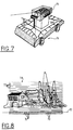
- the field of view of the rangefinder 74 represented in FIG. 8 and designated by the reference 78 then comprises a certain number of horizontal scanning lines 72, the lowest of which is at the level of the first ends of the optical fibers 70. It is possible according to conditions for moving the mobile device 76, sweeping all or part of the observation field 78, including or not including the row of optical fibers 70 therein, and by reducing or increasing the vertical and horizontal dimensions of the observation field .
- this makes it possible to carry out a three-dimensional perception of the environment, a peripheral surveillance gyrotelemeter, or a fiber optic collision avoidance belt.
- a "reflectance" image of the video type of a space area at the same time as the telemetric image of this area.
- This video image can be obtained from the photoreceptor output signal, the intensity of which corresponds to the reflectances of the points in the observed area.
- the video image or the reflectance image thus obtained is independent of the ambient lighting, which can be very useful in certain cases.
- the device according to the invention can be used in "passive" imaging, the laser diode being off and the scanning means operating normally to provide the image of a scene comprising dots or bright or bright objects.
- This technique is interesting in particular in robotics for the monitoring of a joint or weld bead.
- optical fibers used for connection to the scanning means have entry and exit ends treated anti-reflection or whose faces are inclined relative to normal to avoid parasitic reflections. For the same reason, the optical fibers will preferably be separated for the outward and return journeys.
- Optical fibers can also be used in combination with appropriate lenses, to connect the source 10 to the lens 12 and the lens 22 to the receiver 20, these connections being able to have any length, for example between 10 and 100 m, being able to reach 1.000 m, which proves to be interesting when the optical system (12, 22, 64) is placed in a dangerous environment.
- the invention provides for using, instead of a single photoreceptor, an array 20 of photodetectors, such as avalanche photodiodes, comprising for example from 32 to 64 pixels or elementary photodetectors (these components currently being available). It is then also necessary to illuminate the field to be observed with the emission laser diode, which can be done using suitable cylindrical optics. To maintain an appropriate flux balance, we will have to use more powerful laser diodes than in the applications described above, or larger optical pupils.
- the assembly constituted by the laser diode 10, the array 20 of photodetectors, their associated optics and the scanning means is mounted in rotation about a vertical axis to cover a field of 360 ° and is associated with means drive motors in rotation about this axis.
- the scanning means produce a rapid angular deflection of the beam emitted in a substantially vertical plane (in fact, slightly inclined relative to the vertical as a function of the speed of rotation of the above-mentioned assembly) over 15 ° for example , or more depending on the conditions of use.
- the output signals from the photodetectors of the strip are processed in parallel, by means or circuits of the same type as those described in the foregoing. It is thus possible to obtain very high rates of distance measurement, for example from 5 to 10 MHz.
- the speed of the distance calculations makes it possible to carry out a large number of measurements and to take the average. For example 10,000 measurements of a distance make it possible to increase the accuracy by a factor of 100 on the measurement of this distance and to obtain this measurement in a calculation time of approximately 0.15 ms.
Applications Claiming Priority (2)
| Application Number | Priority Date | Filing Date | Title |
|---|---|---|---|
| FR9306971 | 1993-06-10 | ||
| FR9306971A FR2706602B1 (fr) | 1993-06-10 | 1993-06-10 | Télémètre. |
Publications (1)
| Publication Number | Publication Date |
|---|---|
| EP0629880A1 true EP0629880A1 (de) | 1994-12-21 |
Family
ID=9447961
Family Applications (1)
| Application Number | Title | Priority Date | Filing Date |
|---|---|---|---|
| EP94401292A Withdrawn EP0629880A1 (de) | 1993-06-10 | 1994-06-09 | Entfernungsmesser |
Country Status (2)
| Country | Link |
|---|---|
| EP (1) | EP0629880A1 (de) |
| FR (1) | FR2706602B1 (de) |
Cited By (2)
| Publication number | Priority date | Publication date | Assignee | Title |
|---|---|---|---|---|
| CN105372668A (zh) * | 2015-11-16 | 2016-03-02 | 中国电子科技集团公司第二十八研究所 | 一种相位式激光测距方法 |
| CN109633669A (zh) * | 2018-12-28 | 2019-04-16 | 湘潭大学 | 一种利用双波段激光提高焊接中测距精度的方法 |
Families Citing this family (1)
| Publication number | Priority date | Publication date | Assignee | Title |
|---|---|---|---|---|
| FR2761782B1 (fr) * | 1997-04-02 | 1999-05-07 | Commissariat Energie Atomique | Velocimetre et telemetre laser utilisant une detection coherente |
Citations (3)
| Publication number | Priority date | Publication date | Assignee | Title |
|---|---|---|---|---|
| EP0035755A2 (de) * | 1980-03-10 | 1981-09-16 | Tokyo Kogaku Kikai Kabushiki Kaisha | Elektro-optischer Distanzmesser mit drei Modulationsfrequenzen |
| EP0428027A2 (de) * | 1989-11-09 | 1991-05-22 | Firma Carl Zeiss | Optische Entfernungsmessvorrichtung |
| GB2241399A (en) * | 1990-02-13 | 1991-08-28 | Optical Metrology Ltd | Radar measurement apparatus |
-
1993
- 1993-06-10 FR FR9306971A patent/FR2706602B1/fr not_active Expired - Fee Related
-
1994
- 1994-06-09 EP EP94401292A patent/EP0629880A1/de not_active Withdrawn
Patent Citations (3)
| Publication number | Priority date | Publication date | Assignee | Title |
|---|---|---|---|---|
| EP0035755A2 (de) * | 1980-03-10 | 1981-09-16 | Tokyo Kogaku Kikai Kabushiki Kaisha | Elektro-optischer Distanzmesser mit drei Modulationsfrequenzen |
| EP0428027A2 (de) * | 1989-11-09 | 1991-05-22 | Firma Carl Zeiss | Optische Entfernungsmessvorrichtung |
| GB2241399A (en) * | 1990-02-13 | 1991-08-28 | Optical Metrology Ltd | Radar measurement apparatus |
Non-Patent Citations (2)
| Title |
|---|
| VIGNERI: "Dual-Frequency Laser Ranging", INSTRUMENTS AND CONTROL SYSTEMS, vol. 44, no. 4, April 1971 (1971-04-01), RADNOR US, pages 117 - 118 * |
| VOSS ET AL: "Messung des Verschleissprofils in der Spülkante von Glasschmelzwannen mit Hilfe eines lasertechnischen Verfahrens", GLASTECHNISCHE BERICHTE, vol. 54, no. 6, June 1981 (1981-06-01), FRANKFURT DE, pages 149 - 156 * |
Cited By (2)
| Publication number | Priority date | Publication date | Assignee | Title |
|---|---|---|---|---|
| CN105372668A (zh) * | 2015-11-16 | 2016-03-02 | 中国电子科技集团公司第二十八研究所 | 一种相位式激光测距方法 |
| CN109633669A (zh) * | 2018-12-28 | 2019-04-16 | 湘潭大学 | 一种利用双波段激光提高焊接中测距精度的方法 |
Also Published As
| Publication number | Publication date |
|---|---|
| FR2706602A1 (fr) | 1994-12-23 |
| FR2706602B1 (fr) | 1995-09-01 |
Similar Documents
| Publication | Publication Date | Title |
|---|---|---|
| US7193720B2 (en) | Optical vibration imager | |
| US20190025431A1 (en) | Precisely controlled chirped diode laser and coherent lidar system | |
| FR2677834A1 (fr) | Systeme d'imagerie laser a barrette detectrice. | |
| JP2004527765A5 (de) | ||
| FR2585484A1 (fr) | Procede et dispositif de pilotage optique | |
| JP2004527765A (ja) | 距離測定用光学センサー | |
| FR2639124A1 (fr) | Velocimetre doppler optique a faisceau de reference pour des mesures multidimensionnelles | |
| FR2615281A1 (fr) | Dispositif de mesure d'une distance en mouvement relatif de deux objets mobiles l'un par rapport a l'autre | |
| EP0255792A1 (de) | Erkennungssystem zusammen mit einem Retroreflektor und einem Laserstrahl-Modulator | |
| FR2568688A1 (fr) | Systeme emetteur-recepteur pour imagerie laser | |
| FR2490808A1 (fr) | Interferometre et dispositif comportant cet interferometre | |
| EP1183549B1 (de) | Verfahren und vorrichtung zur dopplergeschwindigkeitsmessung | |
| EP0629880A1 (de) | Entfernungsmesser | |
| FR2724464A1 (fr) | Dispositif embarquable de mesure de retrodiffusion de lumiere | |
| EP0669535B1 (de) | Verfahren und Vorrichtung zur Messung der relativen Lageveränderung zwischen zwei Bauteilen | |
| EP0282399B1 (de) | System zum Sammeln von durch n bewegliche Stationen optisch übertragenen Daten in einer Feststation | |
| EP0720028B1 (de) | Multifunktionelles, unauffälliges Entfernungsmessgerät | |
| EP4078217B1 (de) | Lidar-system mit zwei diffraktiven komponenten | |
| EP3488227B1 (de) | System und verfahren zur messung eines physikalischen parameters eines mediums | |
| EP3977158A1 (de) | Lidar-system mit einem interferenziellen diffraktiven element und lidar-abbildungsverfahren | |
| EP0591911B1 (de) | Interferometer bestehend aus einer integrierten Anordnung und einem reflektierenden Teil, die durch eine Messzone voneinander getrennt sind | |
| FR2654218A1 (fr) | Systeme optronique de poursuite tridimensionnelle avec alignement automatique d'un telemetre optique sur la cible. | |
| EP1079239B1 (de) | Verfahren und Anordnung zur Zieldiskriminierung mittels Laserbestrahlung | |
| FR2677456A1 (fr) | Systeme laser a detection heterodyne avec reduction des effets de la lumiere parasite. | |
| FR2688317A1 (fr) | Dispositif d'analyse spatiale a onde laser, notamment pour autodirecteur de missile. |
Legal Events
| Date | Code | Title | Description |
|---|---|---|---|
| PUAI | Public reference made under article 153(3) epc to a published international application that has entered the european phase |
Free format text: ORIGINAL CODE: 0009012 |
|
| AK | Designated contracting states |
Kind code of ref document: A1 Designated state(s): AT BE CH DE DK ES FR GB GR IE IT LI LU MC NL PT SE |
|
| RIN1 | Information on inventor provided before grant (corrected) |
Inventor name: MILLET, JOCELYN Inventor name: LEQUIME, MICHEL Inventor name: DEBRIE, JEAN Inventor name: LEBLAY, PIERRICK Inventor name: ABITBOL, MARC |
|
| STAA | Information on the status of an ep patent application or granted ep patent |
Free format text: STATUS: THE APPLICATION IS DEEMED TO BE WITHDRAWN |
|
| 18D | Application deemed to be withdrawn |
Effective date: 19950622 |