EP0629520A2 - Glass run guides for slidable vehicle windows - Google Patents
Glass run guides for slidable vehicle windows Download PDFInfo
- Publication number
- EP0629520A2 EP0629520A2 EP94303752A EP94303752A EP0629520A2 EP 0629520 A2 EP0629520 A2 EP 0629520A2 EP 94303752 A EP94303752 A EP 94303752A EP 94303752 A EP94303752 A EP 94303752A EP 0629520 A2 EP0629520 A2 EP 0629520A2
- Authority
- EP
- European Patent Office
- Prior art keywords
- guide
- glass run
- window
- vehicle window
- run guide
- Prior art date
- Legal status (The legal status is an assumption and is not a legal conclusion. Google has not performed a legal analysis and makes no representation as to the accuracy of the status listed.)
- Granted
Links
Images

Classifications
-
- E—FIXED CONSTRUCTIONS
- E05—LOCKS; KEYS; WINDOW OR DOOR FITTINGS; SAFES
- E05F—DEVICES FOR MOVING WINGS INTO OPEN OR CLOSED POSITION; CHECKS FOR WINGS; WING FITTINGS NOT OTHERWISE PROVIDED FOR, CONCERNED WITH THE FUNCTIONING OF THE WING
- E05F11/00—Man-operated mechanisms for operating wings, including those which also operate the fastening
- E05F11/38—Man-operated mechanisms for operating wings, including those which also operate the fastening for sliding windows, e.g. vehicle windows, to be opened or closed by vertical movement
- E05F11/382—Man-operated mechanisms for operating wings, including those which also operate the fastening for sliding windows, e.g. vehicle windows, to be opened or closed by vertical movement for vehicle windows
- E05F11/385—Fixing of window glass to the carrier of the operating mechanism
-
- B—PERFORMING OPERATIONS; TRANSPORTING
- B60—VEHICLES IN GENERAL
- B60J—WINDOWS, WINDSCREENS, NON-FIXED ROOFS, DOORS, OR SIMILAR DEVICES FOR VEHICLES; REMOVABLE EXTERNAL PROTECTIVE COVERINGS SPECIALLY ADAPTED FOR VEHICLES
- B60J10/00—Sealing arrangements
- B60J10/15—Sealing arrangements characterised by the material
- B60J10/17—Sealing arrangements characterised by the material provided with a low-friction material on the surface
-
- B—PERFORMING OPERATIONS; TRANSPORTING
- B60—VEHICLES IN GENERAL
- B60J—WINDOWS, WINDSCREENS, NON-FIXED ROOFS, DOORS, OR SIMILAR DEVICES FOR VEHICLES; REMOVABLE EXTERNAL PROTECTIVE COVERINGS SPECIALLY ADAPTED FOR VEHICLES
- B60J10/00—Sealing arrangements
- B60J10/20—Sealing arrangements characterised by the shape
- B60J10/23—Sealing arrangements characterised by the shape assembled from two or more parts
- B60J10/235—Sealing arrangements characterised by the shape assembled from two or more parts the parts being joined along their longitudinal direction
-
- B—PERFORMING OPERATIONS; TRANSPORTING
- B60—VEHICLES IN GENERAL
- B60J—WINDOWS, WINDSCREENS, NON-FIXED ROOFS, DOORS, OR SIMILAR DEVICES FOR VEHICLES; REMOVABLE EXTERNAL PROTECTIVE COVERINGS SPECIALLY ADAPTED FOR VEHICLES
- B60J10/00—Sealing arrangements
- B60J10/70—Sealing arrangements specially adapted for windows or windscreens
- B60J10/74—Sealing arrangements specially adapted for windows or windscreens for sliding window panes, e.g. sash guides
-
- E—FIXED CONSTRUCTIONS
- E05—LOCKS; KEYS; WINDOW OR DOOR FITTINGS; SAFES
- E05Y—INDEXING SCHEME RELATING TO HINGES OR OTHER SUSPENSION DEVICES FOR DOORS, WINDOWS OR WINGS AND DEVICES FOR MOVING WINGS INTO OPEN OR CLOSED POSITION, CHECKS FOR WINGS AND WING FITTINGS NOT OTHERWISE PROVIDED FOR, CONCERNED WITH THE FUNCTIONING OF THE WING
- E05Y2201/00—Constructional elements; Accessories therefore
- E05Y2201/60—Suspension or transmission members; Accessories therefore
- E05Y2201/622—Suspension or transmission members elements
- E05Y2201/684—Rails
-
- E—FIXED CONSTRUCTIONS
- E05—LOCKS; KEYS; WINDOW OR DOOR FITTINGS; SAFES
- E05Y—INDEXING SCHEME RELATING TO HINGES OR OTHER SUSPENSION DEVICES FOR DOORS, WINDOWS OR WINGS AND DEVICES FOR MOVING WINGS INTO OPEN OR CLOSED POSITION, CHECKS FOR WINGS AND WING FITTINGS NOT OTHERWISE PROVIDED FOR, CONCERNED WITH THE FUNCTIONING OF THE WING
- E05Y2600/00—Mounting or coupling arrangements for elements provided for in this subclass
- E05Y2600/10—Adjustable or movable
-
- E—FIXED CONSTRUCTIONS
- E05—LOCKS; KEYS; WINDOW OR DOOR FITTINGS; SAFES
- E05Y—INDEXING SCHEME RELATING TO HINGES OR OTHER SUSPENSION DEVICES FOR DOORS, WINDOWS OR WINGS AND DEVICES FOR MOVING WINGS INTO OPEN OR CLOSED POSITION, CHECKS FOR WINGS AND WING FITTINGS NOT OTHERWISE PROVIDED FOR, CONCERNED WITH THE FUNCTIONING OF THE WING
- E05Y2900/00—Application of doors, windows, wings or fittings thereof
- E05Y2900/50—Application of doors, windows, wings or fittings thereof for vehicles
- E05Y2900/53—Application of doors, windows, wings or fittings thereof for vehicles characterised by the type of wing
- E05Y2900/55—Windows
Definitions
- This specification relates generally to glass run guide members disposed within an automotive vehicle door having a slidable window, and which serve to smoothly guide the window as it is being lowered into or raised from the well of the door.
- Automotive vehicle doors are almost invariably provided with a sliding window which can be raised to a position sealingly closing a window opening and which can be lowered to a position wherein the window is stored in a cavity within the vehicle door.
- the periphery of the window opening in a vehicle door is generally provided with a plurality of polymeric sealing elements having resilient elastomeric characteristics to allow for smooth movement of the window and to ensure sealing engagement between the window and that portion of the door frame defining the window opening, even after thousands of cycles between the open and closed positions over many years of service.
- the sealing elements surrounding the window opening generally include a header and pillar or side elements which typically have a substantially U-shaped portion into which the edges of the window are received, and a pair of opposing inner and outer beltline sealing elements which are attached to the door frame along the lower edge of the window opening.
- the header, pillar and beltline sealing elements are generally attached to a pinchweld flange or U-shaped channel formed by the sheet metal defining the doorframe, with the door frame serving as a reinforcement for the sealing elements to stabilize or counter forces exerted by the window along its edges as it is being raised or lowered.
- the window is typically guided by a pair of spaced parallel rails or glass runs.
- the belowbelt glass runs generally comprise an elastic U-shaped member of, for example, rubber which does not serve a sealing function, but instead provides a nonabrasive, low-friction guide liner which promotes smooth movement of the window as it is being raised or lowered.
- the edges of the door frame below the beltline are not in close proximity to the belowbelt glass runs and are therefore unavailable for providing reinforcing support to the elastic member or guide liner to stabilize or counter forces exerted by the window along its edges when it is being raised or lowered as is the case with the window sealing elements.
- conventional belowbelt guide means generally include a rigid retainer having a U-shaped cross section into which the guide liner is received.
- the rigid retainer is generally made of a tough, high modulus material such as steel and is rigidly fixed to the frame as by welding or mechanical fasteners.
- the rigid retainer supports the guide liner and acts to stabilize forces exerted onto the belowbelt glass run by the window especially when it is being raised or lowered.
- a typical prior art belowbelt glass run 45 comprising an underlying steel support member having a U-shaped channel and an elastomeric liner received within the U-shaped channel is shown.
- Conventional belowbelt glass runs comprising a support member and separate guide liner are generally adequate for holding the glass on track with a smooth, consistent motion as the window is being raised or lowered in the door.
- Automobile and automotive component manufacturers are, however, continually endeavoring to provide high quality components which meet or exceed consumer expectations while simultaneously reducing manufacturing and assembly costs. Accordingly, a below-belt glass run design which is capable of smoothly guiding a window of a vehicle door and which incorporates a simpler design comprising fewer components, and so with low manufacturing and assembly costs, would be highly desirable.
- the guide consists essentially of an elongate polymeric member for mounting in the vehicle body extending in the sliding direction of the window pane, the member having a base and opposed side walls defining a stiff, self-supporting channel to receive the edge of the window pane and restrain it against movement transverse to the sliding direction.
- the guide has longitudinally local securing locations or securing means, spaced along its length, for securing it to the vehicle body.
- each of its side walls carries (preferably formed in one piece therewith) a relatively flexible contact lip which bears slidably and resiliently against the respective window pane surface, for fine guiding of the sliding movement.
- the contact lip is preferably formed as a cantilever or "finger" portion, desirably having a arcuate cross-section which is convex where it contacts the window pane.
- each side wall may comprise, in one piece, a thick, stiff side wall portion to restrain the pane against undesired lateral or "skew” movements, and a thin, flexible contact lip portion for fine guiding of the sliding movement.
- a low-friction coating or flocking is preferred on the contact lip, and optionally elsewhere as well.
- the pane-receiving portion of the member may be of substantially uniform cross-section along its length.
- the polymeric member Since the polymeric member has sufficient rigidity to support its own shape and restrain the pane against undesired movements, it can be mounted in the vehicle body without the coextensive rigid support required in the prior art.
- the polymer member may be formed in one piece, or more preferably in two pieces which are subsequently joined along a longitudinal joint. Moulding is the preferred method. Fibre-reinforced plastic is the preferred material.
- Another general aspect is an automobile door window assembly in which a window pane is slidable in a vehicle body window opening under of the control of a window regulator mechanism, and front and rear glass run guides as described above are mounted in the vehicle door to extend below the window opening in the sliding direction, to receive the front and rear pane edges and thereby guide and restrain the movement of the pane.
- Each guide member may be fixed to the door structure only at longitudinally-localised portions thereof.
- Another general aspect is a moulding method in which inboard and outboard portions of the element are separately formed and then joined to one another to form the channel section. Preferred features are described later.
- a glass run channel including an integrated one-piece glass run guide member, is made from a polymer based composition and has sufficient rigidity to stabilize and effectively counteract forces exerted by the slidable window, along the edges thereof, on to the glass run channel, especially while the window is either being raised from or lowered into the door cavity or well.
- the polymer based composition in addition to having sufficient rigidity to eliminate the need for a separate underlying support member has sufficient resilience and a non-abrasive, low friction surface suitable for promoting smooth tracking of the window as- it is being raised or lowered.
- the glass run channel of the invention is preferably made of a fiber reinforced thermoplastic material to provide the aforementioned desirable combination of properties.
- a one-piece glass run channel of another aspect proposed herein comprises a curved strip having a substantially constant generally U-shaped cross section.
- Each leg of the U-shaped cross section has a projecting lip portion, one of which engages the inner surface of the window pane near its edge, while the other engages the outer surface of the window pane near its edge to smoothly guide the window during travel between the fully raised or closed position and the fully lowered position of the window.
- the one-piece glass run channel in addition to smoothly guiding the window also has sufficient strength and rigidity to counter forces exerted from the side edges of the sliding window, thereby eliminating the need for separate belowbelt retainers.
- a simple efficient one-piece glass run guide assembly for a slidable vehicle window which reduces the number of components needed, thereby reducing the amount of time and effort required for installation of the glass run guides, and providing an effective lower cost alternative to conventional glass run assemblies having separate guide and retainer means, can be provided.
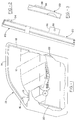
- a left front door 10 of an automobile provided with a slidable glass window 12.
- the window is capable of being raised or lowered by any of various door window regulator means (not shown) e.g. as well known in the art.
- the window opening is defined by an upper or header section 14 of the door frame, a pair of laterally spaced pillars 16 and 18, respectively known in the art as the A and B-pillars, and the upper edge of the sheet metal door panels, known in the art as the beltline 19.
- the window is guided by sealing elements attached to the door frame along the periphery of the window opening, and retained or restrained from undesirable inboard, outboard, forward and backward movement by the header and pillar sections of the door frame.
- the window is guided by a pair of parallel laterally spaced guide members 20 and 22. Because the guide means 20 and 22, particularly the forward guide means 20, are spaced away from the edges of the door frame, the door frame is generally not capable of serving as a retainer means for restraining the window against undesirable inboard, outboard, forward and backward movement of the window. Accordingly, the guide means 20 and 22 must serve the dual functions of providing a resilient, non-abrasive surface which smoothly guides the window along its edges during raising or lowering of the window, and of providing reinforcement or support to counter forces exerted from the edges of the sliding window to prevent undesirable movement thereof.
- Each guide means 20 and 22 comprises a one-piece component molded from a polymeric material.
- the guide means 20 and 22 are generally similar and will therefore be described with reference to the forward guide means 20, shown in Figs. 2-4; the details of the rearward guide means 22 being readily determinable and obvious from the description of the forward guide means 20.
- Fig. 2 there is shown a side elevational view of forward guide means 20 as seen when facing the inboard side of the guide means.
- Current vehicle body designs generally include doors and door windows having a small amount of outward curvature, i.e. the exterior surfaces of the door and door window have a generally large radius curved surface about an axis generally parallel with the longitudinal axis of the vehicle.
- the guide means 20 is preferably a curved strip as shown in Fig. 3 to accommodate the curvature of the window 12.
- the guide means 20 generally has a substantially U-shaped overall transverse cross section including a base 24, an inboard leg 26 and an outboard leg 28.
- the inboard and outboard legs, 26 and 28 respectively, include projecting lip portions 30 and 32 which engage the interior and exterior surfaces respectively of window 12 to smoothly guide it during its upward or downward travel.
- mounting means are integrally formed during the molding of the guide means.
- the mounting means preferably includes an integral clip 34 near the upper end of the guide means 20 and 22, and a fastening lug 36 near the bottom end of the guide means and having a central hole 38 for receiving a conventional fastener, such as a threaded bolt which can also, for example, pass through a corresponding hole in the door frame, to fasten the guide means to the door frame.
- the clip 34 can be adapted to be received in a slotted opening of the door frame, thus simplifying installation procedure so as to include, for example, the steps of sliding the clip through the slotted opening of the frame, and using a single bolt to rigidly secure the guide means 20 to the door frame.
- the disclosed cross-sectional shapes for the guide means and the mounting means for securing the guide means to the vehicle door can be readily modified, or adapted to be used in vehicle doors having a variety of different shapes and designs.
- the guide means 20 and 22 are each formed with separate inboard and outboard guide elements 40 and 42, respectively, which are subsequently fused or otherwise joined to one another to provide for a practical, cost effective means of mass production.
- Such guide means may be produced by a split mold process wherein the inboard and outboard guide elements 40 and 42 are simultaneously injection molded in a mold assembly having two mold cavities separated by a removable divider plate. The mold is opened after the two guide elements are formed and the divider plate is removed. After the divider plate has been removed, adhesives are applied to selected surfaces of one or both of the guide elements 40 and 42.
- the mold With the adhesive having been applied to at least one of the guide elements, the mold is reclosed without the divider and the two guide elements are bonded to one another to form a one-piece guide member, such as 20 or 22, which is adapted to facilitate smooth movement of the glass window 12 as it is being raised or lowered and to provide rigid retaining means whereby forces exerted from the edges of the window are countered to inhibit or prevent undesirable inboard, outboard, forward or rearward movement of the window.
- the guide elements 40 and 42 are preferably formed with interlocking means, such as a tongue 43 and groove 44, which facilitate or enhance joining of the guide elements.
- interlocking means such as a tongue 43 and groove 44
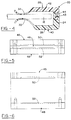
- FIG. 5 - 8 An embodiment of injection press molding apparatus suitable for forming glass run guide members as set out above is shown in Figs. 5 - 8.
- the mold generally comprises an upper die plate 45, a removable divider plate 46, and a lower die plate 48.
- the upper die plate and one side of the removable divider plate together define the mold cavity 50 for one of the guide elements 40 or 42, and the lower die plate and the other side of the removable divider plate together define the mold cavity 52 for the other guide element.
- a suitable moldable thermoplastic or thermosetting polymeric composition preferably containing fiber reinforcement, is substantially simultaneously injected into both of the mold cavities 50 and 52.
- Thermoplastic polymers are generally preferred because they have lower cycle times and are more easily compounded to consistently and repeatedly produce seal assemblies having any of a wide variety of desirable properties.
- the mold is opened and the divider plate 46 is removed as shown in Fig. 6.
- adhesive materials are then applied to selected surfaces of the inboard, outboard, or both guide elements, preferably by preprogrammed robotic means 54 as shown in Fig. 7.
- functional coating such as flocking adhesive or low friction coating, can be applied if desired, also preferably by preprogrammed robotic means 56.
- the mold is again closed, without the divider between the inner and outer dies, to secure the guide elements 40 and 42 together.
- heat can be applied to the mold to, for example, cure the adhesive if a heat curable adhesive is selected, or to fuse the elements together to form a one-piece guide means, such as 20 or 22.
- the mold is then opened and optionally flocking can be applied if desired.
- an optional low friction coating can be applied to selected surfaces such as the surfaces of the lip portions 30 and 32 which contact the surfaces of window 12.
- the completed guide means 20 or 22 is then removed from the mold and the process can then be repeated to produce additional guide means.
- the guide means can be formed in a mold assembly having a single mold cavity.
- the aforementioned split mold process is preferred.
- the guide means be provided with a low friction, non-abrasive surface for engaging the interior and exterior surfaces of the window near the edges thereof to provide for smooth movement of the window along the guide during raising or lowering of the window, while simultaneously having sufficient strength and rigidity to counter the forces exerted by the edges of the window to prevent undesirable inboard, outboard, forward or rearward movement during normal operation of the window.
- the window guide means should be of a resilient polymeric material simultaneously possessing a low coefficient of friction with glass, and a relatively high modulus, flexural and tensile strength.
- Suitable thermoplastics include polypropylene, polyamide, polyester, polyurethane, polyacetal, polyethylene, polyvinyl chloride, acrylonitrile-butadiene-styrene, acrylic-styrene-acrylonitrile, fluoro polymers, and other typical thermoplastics or alloys thereof.
- Suitable thermosetting compositions include crosslinked polyurethane, high modulus elastomers, such as EPDM, and other suitable thermosets with plastic characteristics such as epoxies.
- the polymeric materials used to form the vehicle door window guide means may be compounded with additives e.g. as known in the art, including antioxidants, antimicrobials, lubricants, mold release agents, plasticizers, and the like, as desired.
- additives e.g. as known in the art, including antioxidants, antimicrobials, lubricants, mold release agents, plasticizers, and the like, as desired.
Abstract
Description
- This specification relates generally to glass run guide members disposed within an automotive vehicle door having a slidable window, and which serve to smoothly guide the window as it is being lowered into or raised from the well of the door.
- Automotive vehicle doors are almost invariably provided with a sliding window which can be raised to a position sealingly closing a window opening and which can be lowered to a position wherein the window is stored in a cavity within the vehicle door. The periphery of the window opening in a vehicle door is generally provided with a plurality of polymeric sealing elements having resilient elastomeric characteristics to allow for smooth movement of the window and to ensure sealing engagement between the window and that portion of the door frame defining the window opening, even after thousands of cycles between the open and closed positions over many years of service. The sealing elements surrounding the window opening generally include a header and pillar or side elements which typically have a substantially U-shaped portion into which the edges of the window are received, and a pair of opposing inner and outer beltline sealing elements which are attached to the door frame along the lower edge of the window opening. The header, pillar and beltline sealing elements are generally attached to a pinchweld flange or U-shaped channel formed by the sheet metal defining the doorframe, with the door frame serving as a reinforcement for the sealing elements to stabilize or counter forces exerted by the window along its edges as it is being raised or lowered.
- Below the beltline, within the door cavity or well, the window is typically guided by a pair of spaced parallel rails or glass runs. The belowbelt glass runs generally comprise an elastic U-shaped member of, for example, rubber which does not serve a sealing function, but instead provides a nonabrasive, low-friction guide liner which promotes smooth movement of the window as it is being raised or lowered. Typically, the edges of the door frame below the beltline are not in close proximity to the belowbelt glass runs and are therefore unavailable for providing reinforcing support to the elastic member or guide liner to stabilize or counter forces exerted by the window along its edges when it is being raised or lowered as is the case with the window sealing elements. Accordingly, conventional belowbelt guide means generally include a rigid retainer having a U-shaped cross section into which the guide liner is received. The rigid retainer is generally made of a tough, high modulus material such as steel and is rigidly fixed to the frame as by welding or mechanical fasteners. The rigid retainer supports the guide liner and acts to stabilize forces exerted onto the belowbelt glass run by the window especially when it is being raised or lowered.
- In Fig. 3 of U.S. Patent No. 4,098,134, a typical prior art
belowbelt glass run 45 comprising an underlying steel support member having a U-shaped channel and an elastomeric liner received within the U-shaped channel is shown. Conventional belowbelt glass runs comprising a support member and separate guide liner are generally adequate for holding the glass on track with a smooth, consistent motion as the window is being raised or lowered in the door. Automobile and automotive component manufacturers are, however, continually endeavoring to provide high quality components which meet or exceed consumer expectations while simultaneously reducing manufacturing and assembly costs. Accordingly, a below-belt glass run design which is capable of smoothly guiding a window of a vehicle door and which incorporates a simpler design comprising fewer components, and so with low manufacturing and assembly costs, would be highly desirable. - Some aspects of the present proposal are set out in the claims.
- Further independent aspects are set out below.
- One general aspect is a glass run guide for guiding the sliding edge of a slidable vehicle window pane at a location beyond (typically below) the level of a vehicle body window opening, e.g. in a vehicle door. The guide consists essentially of an elongate polymeric member for mounting in the vehicle body extending in the sliding direction of the window pane, the member having a base and opposed side walls defining a stiff, self-supporting channel to receive the edge of the window pane and restrain it against movement transverse to the sliding direction. Typically the guide has longitudinally local securing locations or securing means, spaced along its length, for securing it to the vehicle body.
- Preferably the stiff channel is transversely substantially oversize for the window pane, and each of its side walls carries (preferably formed in one piece therewith) a relatively flexible contact lip which bears slidably and resiliently against the respective window pane surface, for fine guiding of the sliding movement. The contact lip is preferably formed as a cantilever or "finger" portion, desirably having a arcuate cross-section which is convex where it contacts the window pane. Thus, each side wall may comprise, in one piece, a thick, stiff side wall portion to restrain the pane against undesired lateral or "skew" movements, and a thin, flexible contact lip portion for fine guiding of the sliding movement. A low-friction coating or flocking is preferred on the contact lip, and optionally elsewhere as well.
- The pane-receiving portion of the member may be of substantially uniform cross-section along its length.
- Since the polymeric member has sufficient rigidity to support its own shape and restrain the pane against undesired movements, it can be mounted in the vehicle body without the coextensive rigid support required in the prior art.
- The polymer member may be formed in one piece, or more preferably in two pieces which are subsequently joined along a longitudinal joint. Moulding is the preferred method. Fibre-reinforced plastic is the preferred material.
- Another general aspect is an automobile door window assembly in which a window pane is slidable in a vehicle body window opening under of the control of a window regulator mechanism, and front and rear glass run guides as described above are mounted in the vehicle door to extend below the window opening in the sliding direction, to receive the front and rear pane edges and thereby guide and restrain the movement of the pane. Each guide member may be fixed to the door structure only at longitudinally-localised portions thereof.
- Another general aspect is a moulding method in which inboard and outboard portions of the element are separately formed and then joined to one another to form the channel section. Preferred features are described later.
- In accordance with one aspect proposed herein, a glass run channel, including an integrated one-piece glass run guide member, is made from a polymer based composition and has sufficient rigidity to stabilize and effectively counteract forces exerted by the slidable window, along the edges thereof, on to the glass run channel, especially while the window is either being raised from or lowered into the door cavity or well. The polymer based composition, in addition to having sufficient rigidity to eliminate the need for a separate underlying support member has sufficient resilience and a non-abrasive, low friction surface suitable for promoting smooth tracking of the window as- it is being raised or lowered. The glass run channel of the invention is preferably made of a fiber reinforced thermoplastic material to provide the aforementioned desirable combination of properties.
- A one-piece glass run channel of another aspect proposed herein comprises a curved strip having a substantially constant generally U-shaped cross section. Each leg of the U-shaped cross section has a projecting lip portion, one of which engages the inner surface of the window pane near its edge, while the other engages the outer surface of the window pane near its edge to smoothly guide the window during travel between the fully raised or closed position and the fully lowered position of the window. The one-piece glass run channel in addition to smoothly guiding the window also has sufficient strength and rigidity to counter forces exerted from the side edges of the sliding window, thereby eliminating the need for separate belowbelt retainers.
- A simple efficient one-piece glass run guide assembly for a slidable vehicle window, which reduces the number of components needed, thereby reducing the amount of time and effort required for installation of the glass run guides, and providing an effective lower cost alternative to conventional glass run assemblies having separate guide and retainer means, can be provided.
-
- Fig. 1 is a side elevation view of a vehicle door having a slidable window, portions are broken away to show the guide members contained within the door well;
- Fig. 2 is a side elevation view of a guide member;
- Fig. 3 is a front elevation view of the guide member of Fig. 2;
- Fig. 4 is a transverse cross-sectional view of the guide member shown in Figs. 2 and 3;
- Fig. 5 is an elevation view of a molding apparatus for molding a guide member;
- Fig. 6 is an elevation view of the molding apparatus of Fig. 5 with the mold open and with the divider plate removed;
- Fig. 7 is an elevation view of the molding apparatus of Fig. 5 with the mold open and showing robotic means in phantom for applying adhesive and optional functional coating; and
- Fig. 8 is an elevation view of the molding apparatus of Fig. 5 showing the mold closed with the divider plate removed.
- There is shown in Fig. 1 a left
front door 10 of an automobile provided with aslidable glass window 12. The window is capable of being raised or lowered by any of various door window regulator means (not shown) e.g. as well known in the art. The window opening is defined by an upper orheader section 14 of the door frame, a pair of laterally spacedpillars beltline 19. Above the beltline, the window is guided by sealing elements attached to the door frame along the periphery of the window opening, and retained or restrained from undesirable inboard, outboard, forward and backward movement by the header and pillar sections of the door frame. Below the beltline, the window is guided by a pair of parallel laterally spacedguide members - Each guide means 20 and 22 comprises a one-piece component molded from a polymeric material. The guide means 20 and 22 are generally similar and will therefore be described with reference to the forward guide means 20, shown in Figs. 2-4; the details of the rearward guide means 22 being readily determinable and obvious from the description of the forward guide means 20.
- In Fig. 2, there is shown a side elevational view of forward guide means 20 as seen when facing the inboard side of the guide means. Current vehicle body designs generally include doors and door windows having a small amount of outward curvature, i.e. the exterior surfaces of the door and door window have a generally large radius curved surface about an axis generally parallel with the longitudinal axis of the vehicle. Accordingly, the guide means 20 is preferably a curved strip as shown in Fig. 3 to accommodate the curvature of the
window 12. - A transverse cross sectional view of the guide means 20 is shown in Fig. 4. The guide means generally has a substantially U-shaped overall transverse cross section including a
base 24, aninboard leg 26 and anoutboard leg 28. The inboard and outboard legs, 26 and 28 respectively, include projectinglip portions window 12 to smoothly guide it during its upward or downward travel. - In accordance with a preferred aspect herein, mounting means are integrally formed during the molding of the guide means. The mounting means preferably includes an
integral clip 34 near the upper end of the guide means 20 and 22, and afastening lug 36 near the bottom end of the guide means and having acentral hole 38 for receiving a conventional fastener, such as a threaded bolt which can also, for example, pass through a corresponding hole in the door frame, to fasten the guide means to the door frame. Theclip 34 can be adapted to be received in a slotted opening of the door frame, thus simplifying installation procedure so as to include, for example, the steps of sliding the clip through the slotted opening of the frame, and using a single bolt to rigidly secure the guide means 20 to the door frame. - As will be readily appreciated by those of ordinary skill in the art, the disclosed cross-sectional shapes for the guide means and the mounting means for securing the guide means to the vehicle door can be readily modified, or adapted to be used in vehicle doors having a variety of different shapes and designs.
- In accordance with one preferred version the guide means 20 and 22 are each formed with separate inboard and
outboard guide elements outboard guide elements guide elements glass window 12 as it is being raised or lowered and to provide rigid retaining means whereby forces exerted from the edges of the window are countered to inhibit or prevent undesirable inboard, outboard, forward or rearward movement of the window. Theguide elements tongue 43 andgroove 44, which facilitate or enhance joining of the guide elements. Thus, while it is presently preferred that the guide elements be joined by a combination of adhesives and interlocking means, it is also possible to secure the guide elements together using adhesives alone or interlocking means alone. - An embodiment of injection press molding apparatus suitable for forming glass run guide members as set out above is shown in Figs. 5 - 8. The mold generally comprises an
upper die plate 45, aremovable divider plate 46, and alower die plate 48. The upper die plate and one side of the removable divider plate together define themold cavity 50 for one of theguide elements mold cavity 52 for the other guide element. With the mold closed as shown in Fig. 5, a suitable moldable thermoplastic or thermosetting polymeric composition, preferably containing fiber reinforcement, is substantially simultaneously injected into both of themold cavities - After the inboard and outboard guide elements have been formed, the mold is opened and the
divider plate 46 is removed as shown in Fig. 6. With the mold open, adhesive materials are then applied to selected surfaces of the inboard, outboard, or both guide elements, preferably by preprogrammedrobotic means 54 as shown in Fig. 7. Additionally, functional coating, such as flocking adhesive or low friction coating, can be applied if desired, also preferably by preprogrammedrobotic means 56. Thereafter, as shown in Fig. 8, the mold is again closed, without the divider between the inner and outer dies, to secure theguide elements lip portions window 12. The completed guide means 20 or 22 is then removed from the mold and the process can then be repeated to produce additional guide means. - Alternatively, the guide means can be formed in a mold assembly having a single mold cavity. However, due to the complicated geometry of the guide means, the aforementioned split mold process is preferred.
- An important characteristic is that the guide means be provided with a low friction, non-abrasive surface for engaging the interior and exterior surfaces of the window near the edges thereof to provide for smooth movement of the window along the guide during raising or lowering of the window, while simultaneously having sufficient strength and rigidity to counter the forces exerted by the edges of the window to prevent undesirable inboard, outboard, forward or rearward movement during normal operation of the window. Accordingly, the window guide means should be of a resilient polymeric material simultaneously possessing a low coefficient of friction with glass, and a relatively high modulus, flexural and tensile strength. Suitable thermoplastics include polypropylene, polyamide, polyester, polyurethane, polyacetal, polyethylene, polyvinyl chloride, acrylonitrile-butadiene-styrene, acrylic-styrene-acrylonitrile, fluoro polymers, and other typical thermoplastics or alloys thereof. Suitable thermosetting compositions include crosslinked polyurethane, high modulus elastomers, such as EPDM, and other suitable thermosets with plastic characteristics such as epoxies.
- The polymeric materials used to form the vehicle door window guide means may be compounded with additives e.g. as known in the art, including antioxidants, antimicrobials, lubricants, mold release agents, plasticizers, and the like, as desired.
Claims (19)
- A one-piece glass run guide for a slidable vehicle window, comprising a molded polymeric strip having a substantially U-shaped transverse cross section including a base, an inboard leg and an outboard leg, each of the legs having a projecting lip portion which engages interior and exterior surfaces, respectively, of a slid-able vehicle window.
- A glass run guide as set forth in claim 1, which comprises separate molded inboard and outboard guide elements which are joined to each other.
- A glass run guide as set forth in claim 2, wherein the guide elements are joined to each other by an adhesive composition.
- A glass run guide of claim 2 or 3 wherein the guide elements are joined to each other by interlocking means integrally formed during molding of the guide elements.
- A glass run guide as set forth in claim 4, wherein the interlocking means are a groove formed on one of the elements and a cooperating interlocking tongue formed on the other element.
- A glass run guide of any preceding claim, comprising mounting means integrally formed during molding of the guide.
- A glass run guide as set forth in claim 6, wherein the mounting means includes a clip.
- A glass run guide of claim 6 or 7 wherein the mounting means includes a fastening lug having a hole through which a fastener can be passed for securing the glass run guide to a vehicle door frame.
- A glass run guide of any preceding claim, which has sufficient strength and rigidity to counter forces exerted by a sliding vehicle window during normal operation thereof to prevent undesirable inboard, outboard, forward and rearward movement of the window.
- A glass run guide of any preceding claim, wherein at least the surfaces of the lip portions which contact the surfaces of the slidable vehicle window are low friction, non-abrasive surfaces which provide for smooth movement of the window along the guide during raising or lowering of the window.
- A glass run guide as set forth in claim 10, wherein a low friction coating is applied to the surfaces of the lip portions which contact the surfaces of the slidable vehicle window.
- A glass run guide as set forth in claim 10, wherein flocking is applied to the surfaces of the lip portions which contact the surfaces of the slidable vehicle window.
- A glass run guide of any prededing claim, which is formed from a fiber reinforced thermoplastic polymer composition.
- A glass run guide as set forth in claim 13, wherein the fiber reinforcement is glass fiber, and wherein the thermoplastic is selected from the group consisting of EPDM, polypropylene, polyamide, polyester, polyurethane, polyacetal, polyethylene, polyvinyl chloride, acrylonitrile-butadiene-styrene, acrylic-styreneacrylonitrile, fluoro polymers, and other typical thermoplastics and alloys thereof.
- A glass run guide of any of claims 1 - 12 which is formed from a fiber reinforced thermosetting polymer composition.
- A glass run guide as set forth in claim 15, wherein the fiber reinforcement is glass fiber, and wherein the thermosetting polymer is selected from the group consisting of unsaturated polyesters, crosslinked polyurethane, high modulus elastomers, and epoxy resins.
- A one-piece glass run guide for a slidable vehicle window, comprising a molded polymeric strip having a substantially U-shaped transverse cross section including a base, an inboard leg having a projecting lip portion which engages an interior surface of a slidable vehicle window, an outboard leg having a projecting lip portion which engages an exterior surface of the slidable vehicle window; the surfaces of the lip portions which contact the surfaces of the slidable vehicle window being low friction, non-abrasive surfaces to provide for smooth movement of the window along the guide during raising or lowering of the window; the guide being formed of a fiber reinforced polymer having sufficient strength and rigidity to counter forces exerted by the sliding vehicle window to prevent undesirable inboard, outboard, forward and rearward movement of the window; and integral mounting means for fastening the guide to a vehicle door frame.
- A glass run guide as set forth in claim 17, which is formed from a glass fiber reinforced thermoplastic polymer composition, and wherein the thermoplastic polymer is selected from the group consisting of EPDM, polypropylene, polyamide, polyester, polyurethane, polyacetal, polyethylene, polyvinyl chloride, acrylonitrile-butadiene-styrene, acrylic-styrene-acrylonitrile, fluoro polymers, and other typical thermoplastics and alloys thereof.
- A glass run guide as set forth in claim 17, which is formed from a glass fiber reinforced thermosetting polymer composition, and wherein the thermosetting polymer is crosslinked polyurethane, high modulus elastomers, or epoxy resin.
Applications Claiming Priority (2)
| Application Number | Priority Date | Filing Date | Title |
|---|---|---|---|
| US08/067,197 US5345718A (en) | 1993-05-25 | 1993-05-25 | Glass run guide for slidable vehicle window |
| US67197 | 1998-04-27 |
Publications (3)
| Publication Number | Publication Date |
|---|---|
| EP0629520A2 true EP0629520A2 (en) | 1994-12-21 |
| EP0629520A3 EP0629520A3 (en) | 1995-03-01 |
| EP0629520B1 EP0629520B1 (en) | 1998-04-08 |
Family
ID=22074358
Family Applications (1)
| Application Number | Title | Priority Date | Filing Date |
|---|---|---|---|
| EP94303752A Expired - Lifetime EP0629520B1 (en) | 1993-05-25 | 1994-05-25 | Glass run guides for slidable vehicle windows |
Country Status (6)
| Country | Link |
|---|---|
| US (2) | US5345718A (en) |
| EP (1) | EP0629520B1 (en) |
| JP (1) | JP2836010B2 (en) |
| KR (1) | KR0143377B1 (en) |
| CA (1) | CA2123066C (en) |
| DE (1) | DE69409432T2 (en) |
Cited By (1)
| Publication number | Priority date | Publication date | Assignee | Title |
|---|---|---|---|---|
| US5461830A (en) * | 1993-05-25 | 1995-10-31 | Gencorp Inc. | Glass run guide for slidable vehicle window |
Families Citing this family (21)
| Publication number | Priority date | Publication date | Assignee | Title |
|---|---|---|---|---|
| FR2743028B1 (en) * | 1996-01-03 | 1998-03-20 | Billard Catherine | SEALING ELEMENT, IN PARTICULAR FOR MOUNTING AROUND THE OPENING OF DOORS OF MOTOR VEHICLES |
| US5651217A (en) * | 1996-01-25 | 1997-07-29 | The Standard Products Company | Flexible glass run with rigid molded support |
| JP3294494B2 (en) * | 1996-03-05 | 2002-06-24 | オーエム工業株式会社 | Resin lower sash |
| JPH10129896A (en) * | 1996-10-30 | 1998-05-19 | Nec Data Terminal Ltd | Skewing correcting mechanism for continuous paper |
| US5943823A (en) * | 1997-02-06 | 1999-08-31 | Om Corporation | Lower sash made of synthetic resin for automotive vehicle door |
| DE19833185A1 (en) * | 1998-07-23 | 2000-02-03 | Ticona Gmbh | Door module for motor vehicles with functional elements made of plastic |
| GB2388866B (en) * | 1999-06-03 | 2004-01-07 | Gencorp Property Inc | Sealing or guiding arrangements |
| ES2288187T3 (en) | 2002-04-03 | 2008-01-01 | Grupo Antolin-Ingenieria, S.A. | ELEVALUNAS LIGHT FOR VEHICLES. |
| US6962350B2 (en) | 2002-08-13 | 2005-11-08 | Cooper-Standard Automotive Inc. | Insertable wear strip for glass run seals |
| KR100424725B1 (en) * | 2002-10-17 | 2004-03-27 | 이환덕 | Manufacturing method of insert injection molding of automobile |
| DE20304270U1 (en) * | 2003-03-18 | 2003-05-15 | Baedje K H Meteor Gummiwerke | Sealing strip for a vehicle frame structure |
| US7762614B2 (en) * | 2006-09-28 | 2010-07-27 | Toyoda Gosei Co., Ltd. | Glass run |
| JP2008149739A (en) * | 2006-12-14 | 2008-07-03 | Toyoda Gosei Co Ltd | Glass run |
| JP4858225B2 (en) * | 2007-02-26 | 2012-01-18 | 豊田合成株式会社 | Glass run |
| US20080209814A1 (en) * | 2007-03-02 | 2008-09-04 | Timothy Tarjeft | Retainer assembly |
| US20090039672A1 (en) * | 2007-07-30 | 2009-02-12 | Toyoda Gosei Co., Ltd. | Glass run and manufacturing method thereof |
| JP4548457B2 (en) * | 2007-07-30 | 2010-09-22 | 豊田合成株式会社 | Glass run |
| JP4548458B2 (en) * | 2007-07-30 | 2010-09-22 | 豊田合成株式会社 | Glass run |
| DE102015209762A1 (en) * | 2015-05-28 | 2016-12-01 | Bayerische Motoren Werke Aktiengesellschaft | Method for producing SMC hollow components |
| DE102016002681B3 (en) * | 2016-03-04 | 2017-03-23 | CADEA-Gesellschaft für Anwendung und Realisierung computerunterstützter Systeme mbH | Sealing and cover strip for the B-pillar of a passenger car |
| WO2023225193A1 (en) * | 2022-05-18 | 2023-11-23 | Henniges Automotive Sealing Systemsnorth America, Inc. | Flush glass system |
Citations (1)
| Publication number | Priority date | Publication date | Assignee | Title |
|---|---|---|---|---|
| US4969293A (en) * | 1988-07-28 | 1990-11-13 | Hutchinson | Guiding slideway strip for a moving glass, in particular the glass of a car window |
Family Cites Families (28)
| Publication number | Priority date | Publication date | Assignee | Title |
|---|---|---|---|---|
| US3858356A (en) * | 1973-02-14 | 1975-01-07 | Johnson & Son Inc S C | Sashless window structure |
| JPS5215018A (en) * | 1975-07-25 | 1977-02-04 | Toyota Motor Corp | Apparatus to move curved plate |
| DE2807115C2 (en) * | 1978-02-20 | 1979-12-06 | Schlegel Gmbh, 2000 Hamburg | Method for applying a self-locking profile strip to a retaining flange and profile strips for carrying out the method |
| JPS5919877U (en) * | 1982-07-30 | 1984-02-07 | 橋本フオ−ミング工業株式会社 | Car door - Satsushi lower - |
| JPS59102870U (en) * | 1982-12-28 | 1984-07-11 | 橋本フオ−ミング工業株式会社 | Installation structure of window glass guide parts |
| JPS60164580U (en) * | 1984-04-10 | 1985-11-01 | 盟和産業株式会社 | grass run |
| JPS6123461U (en) * | 1984-07-18 | 1986-02-12 | 三菱自動車工業株式会社 | fuel injection pump |
| JPS6194417U (en) * | 1984-11-28 | 1986-06-18 | ||
| JPS61109822U (en) * | 1984-12-25 | 1986-07-11 | ||
| JPS6261723U (en) * | 1985-10-08 | 1987-04-16 | ||
| US4649668A (en) * | 1986-02-06 | 1987-03-17 | Sheller-Globe, Inc. | Sealing element for flush mounted movable automobile window |
| JPS62253516A (en) * | 1986-04-28 | 1987-11-05 | Toyoda Gosei Co Ltd | Windshield pane runner for automobile |
| JPS6321135U (en) * | 1986-07-28 | 1988-02-12 | ||
| JPS6423851U (en) * | 1987-08-03 | 1989-02-08 | ||
| US5013379A (en) * | 1988-01-25 | 1991-05-07 | Gencorp Inc. | Cohesive bonding process for forming a laminate of a wear resistant thermoplastic and a weather resistant rubber |
| JPH01131613U (en) * | 1988-02-29 | 1989-09-06 | ||
| US4827669A (en) * | 1988-05-23 | 1989-05-09 | General Motors Corporation | Glass stabilizer for vehicle door assembly |
| GB8914301D0 (en) * | 1989-06-22 | 1989-08-09 | Draftex Ind Ltd | Window sealing and guiding arrangements |
| US5067281A (en) * | 1989-09-26 | 1991-11-26 | Gen Corp Inc. | Door glass cassette for vehicles |
| JP2634934B2 (en) * | 1990-08-31 | 1997-07-30 | 鬼怒川ゴム工業 株式会社 | Forming method of glass run integrated glass guide |
| US5262114A (en) * | 1991-03-13 | 1993-11-16 | Schlegel Corporation | Method of making an injection molded glass guidance component |
| JP2996358B2 (en) * | 1991-04-15 | 1999-12-27 | 井関農機株式会社 | Tractor front window frame |
| US5086586A (en) * | 1991-04-23 | 1992-02-11 | General Motors Corporation | Vehicle side door flush glass system |
| US5095655A (en) * | 1991-04-23 | 1992-03-17 | General Motors Corporation | Vehicle side door assembly having four sided flush glass window |
| JPH0531785A (en) * | 1991-07-30 | 1993-02-09 | Kinugawa Rubber Ind Co Ltd | Manufacture of weatherstrip |
| US5345718A (en) * | 1993-05-25 | 1994-09-13 | Gencorp Inc. | Glass run guide for slidable vehicle window |
| JP3019713U (en) * | 1995-06-22 | 1996-01-12 | 株式会社愛洋産業 | Bucket inner wall protection member |
| JP3051616U (en) * | 1998-02-19 | 1998-09-02 | 始 小林 | Baked cooker |
-
1993
- 1993-05-25 US US08/067,197 patent/US5345718A/en not_active Expired - Lifetime
-
1994
- 1994-05-06 CA CA002123066A patent/CA2123066C/en not_active Expired - Fee Related
- 1994-05-25 JP JP6135071A patent/JP2836010B2/en not_active Expired - Fee Related
- 1994-05-25 EP EP94303752A patent/EP0629520B1/en not_active Expired - Lifetime
- 1994-05-25 DE DE69409432T patent/DE69409432T2/en not_active Expired - Fee Related
- 1994-05-25 KR KR1019940011437A patent/KR0143377B1/en not_active IP Right Cessation
- 1994-09-02 US US08/300,673 patent/US5461830A/en not_active Expired - Fee Related
Patent Citations (1)
| Publication number | Priority date | Publication date | Assignee | Title |
|---|---|---|---|---|
| US4969293A (en) * | 1988-07-28 | 1990-11-13 | Hutchinson | Guiding slideway strip for a moving glass, in particular the glass of a car window |
Cited By (1)
| Publication number | Priority date | Publication date | Assignee | Title |
|---|---|---|---|---|
| US5461830A (en) * | 1993-05-25 | 1995-10-31 | Gencorp Inc. | Glass run guide for slidable vehicle window |
Also Published As
| Publication number | Publication date |
|---|---|
| CA2123066A1 (en) | 1994-11-26 |
| JP2836010B2 (en) | 1998-12-14 |
| DE69409432T2 (en) | 1998-09-03 |
| CA2123066C (en) | 1997-11-18 |
| EP0629520B1 (en) | 1998-04-08 |
| DE69409432D1 (en) | 1998-05-14 |
| EP0629520A3 (en) | 1995-03-01 |
| US5345718A (en) | 1994-09-13 |
| US5461830A (en) | 1995-10-31 |
| KR0143377B1 (en) | 1998-08-01 |
| JPH079858A (en) | 1995-01-13 |
Similar Documents
| Publication | Publication Date | Title |
|---|---|---|
| EP0629520B1 (en) | Glass run guides for slidable vehicle windows | |
| EP0420617B1 (en) | Door window cassette for vehicles | |
| US5174066A (en) | Door glass cassette for vehicles | |
| US5038521A (en) | Sealing strips | |
| US8915018B2 (en) | Slider window assembly | |
| US5067281A (en) | Door glass cassette for vehicles | |
| US5317835A (en) | Window enclosure for an automotive upper door frame | |
| US9027282B2 (en) | Modifiable slider glass assemblies for utility cabs and vehicles, and/or methods of making the same | |
| US20040134131A1 (en) | Horizontal slider window assembly | |
| US20030182866A1 (en) | Horizontal slider window assembly | |
| US5519968A (en) | Vehicle window sealing strip with integral downward retaining flange | |
| US20060254149A1 (en) | Long trim member for vehicle and attaching method of the same | |
| CN112118980B (en) | Device for guiding a sliding window in a door of a motor vehicle | |
| US7188659B2 (en) | Injection-molded plastic guide rail | |
| EP1630024A1 (en) | Ascending/descending door glass support structure | |
| PL204410B1 (en) | Joining of a vehicle pane to a contiguous element | |
| JP2004074830A (en) | Weather strip of door for vehicle | |
| KR20090053699A (en) | A belt-molding for a vehicle | |
| US20050120633A1 (en) | Glass run for vehicle | |
| EP1301365A1 (en) | Door and/or window frame | |
| US5500264A (en) | Hollow extrudate | |
| JP2004098768A (en) | Inner belt molding for vehicle and mounting structure thereof | |
| US11247546B2 (en) | Vehicle rear slider window assembly with upper rail co-extruded filler | |
| US5065545A (en) | Panel assembly for vehicles with molded regulator attachment | |
| EP0822109A1 (en) | Window sealing arrangements |
Legal Events
| Date | Code | Title | Description |
|---|---|---|---|
| PUAI | Public reference made under article 153(3) epc to a published international application that has entered the european phase |
Free format text: ORIGINAL CODE: 0009012 |
|
| 17P | Request for examination filed |
Effective date: 19940614 |
|
| AK | Designated contracting states |
Kind code of ref document: A2 Designated state(s): DE |
|
| PUAL | Search report despatched |
Free format text: ORIGINAL CODE: 0009013 |
|
| AK | Designated contracting states |
Kind code of ref document: A3 Designated state(s): DE FR GB IT |
|
| RHK1 | Main classification (correction) |
Ipc: B60J 10/04 |
|
| 17Q | First examination report despatched |
Effective date: 19960403 |
|
| GRAG | Despatch of communication of intention to grant |
Free format text: ORIGINAL CODE: EPIDOS AGRA |
|
| GRAG | Despatch of communication of intention to grant |
Free format text: ORIGINAL CODE: EPIDOS AGRA |
|
| GRAH | Despatch of communication of intention to grant a patent |
Free format text: ORIGINAL CODE: EPIDOS IGRA |
|
| GRAH | Despatch of communication of intention to grant a patent |
Free format text: ORIGINAL CODE: EPIDOS IGRA |
|
| RBV | Designated contracting states (corrected) |
Designated state(s): DE |
|
| GRAA | (expected) grant |
Free format text: ORIGINAL CODE: 0009210 |
|
| AK | Designated contracting states |
Kind code of ref document: B1 Designated state(s): DE |
|
| REF | Corresponds to: |
Ref document number: 69409432 Country of ref document: DE Date of ref document: 19980514 |
|
| PGFP | Annual fee paid to national office [announced via postgrant information from national office to epo] |
Ref country code: DE Payment date: 19980728 Year of fee payment: 5 |
|
| PLBE | No opposition filed within time limit |
Free format text: ORIGINAL CODE: 0009261 |
|
| STAA | Information on the status of an ep patent application or granted ep patent |
Free format text: STATUS: NO OPPOSITION FILED WITHIN TIME LIMIT |
|
| 26N | No opposition filed | ||
| PG25 | Lapsed in a contracting state [announced via postgrant information from national office to epo] |
Ref country code: DE Free format text: LAPSE BECAUSE OF NON-PAYMENT OF DUE FEES Effective date: 20000301 |