EP0628233B1 - Videobildverarbeitung - Google Patents
Videobildverarbeitung Download PDFInfo
- Publication number
- EP0628233B1 EP0628233B1 EP93905479A EP93905479A EP0628233B1 EP 0628233 B1 EP0628233 B1 EP 0628233B1 EP 93905479 A EP93905479 A EP 93905479A EP 93905479 A EP93905479 A EP 93905479A EP 0628233 B1 EP0628233 B1 EP 0628233B1
- Authority
- EP
- European Patent Office
- Prior art keywords
- field
- input
- picture
- generating
- transition
- Prior art date
- Legal status (The legal status is an assumption and is not a legal conclusion. Google has not performed a legal analysis and makes no representation as to the accuracy of the status listed.)
- Expired - Lifetime
Links
- 239000002131 composite material Substances 0.000 claims abstract description 19
- 239000013598 vector Substances 0.000 claims description 33
- 238000000034 method Methods 0.000 claims description 23
- 230000007704 transition Effects 0.000 claims description 18
- 238000009499 grossing Methods 0.000 claims description 11
- 230000002123 temporal effect Effects 0.000 claims description 3
- 230000001419 dependent effect Effects 0.000 claims description 2
- 238000001514 detection method Methods 0.000 claims 1
- 230000000063 preceeding effect Effects 0.000 claims 1
- 230000011664 signaling Effects 0.000 claims 1
- 238000001914 filtration Methods 0.000 abstract description 2
- 238000006073 displacement reaction Methods 0.000 description 6
- 230000000694 effects Effects 0.000 description 3
- 238000006243 chemical reaction Methods 0.000 description 1
- 238000005259 measurement Methods 0.000 description 1
- 238000002156 mixing Methods 0.000 description 1
- 239000000203 mixture Substances 0.000 description 1
Images

Classifications
-
- H—ELECTRICITY
- H04—ELECTRIC COMMUNICATION TECHNIQUE
- H04N—PICTORIAL COMMUNICATION, e.g. TELEVISION
- H04N5/00—Details of television systems
- H04N5/14—Picture signal circuitry for video frequency region
- H04N5/144—Movement detection
- H04N5/145—Movement estimation
-
- H—ELECTRICITY
- H04—ELECTRIC COMMUNICATION TECHNIQUE
- H04N—PICTORIAL COMMUNICATION, e.g. TELEVISION
- H04N19/00—Methods or arrangements for coding, decoding, compressing or decompressing digital video signals
- H04N19/50—Methods or arrangements for coding, decoding, compressing or decompressing digital video signals using predictive coding
- H04N19/503—Methods or arrangements for coding, decoding, compressing or decompressing digital video signals using predictive coding involving temporal prediction
- H04N19/51—Motion estimation or motion compensation
- H04N19/577—Motion compensation with bidirectional frame interpolation, i.e. using B-pictures
-
- H—ELECTRICITY
- H04—ELECTRIC COMMUNICATION TECHNIQUE
- H04N—PICTORIAL COMMUNICATION, e.g. TELEVISION
- H04N19/00—Methods or arrangements for coding, decoding, compressing or decompressing digital video signals
- H04N19/80—Details of filtering operations specially adapted for video compression, e.g. for pixel interpolation
-
- H—ELECTRICITY
- H04—ELECTRIC COMMUNICATION TECHNIQUE
- H04N—PICTORIAL COMMUNICATION, e.g. TELEVISION
- H04N7/00—Television systems
- H04N7/01—Conversion of standards, e.g. involving analogue television standards or digital television standards processed at pixel level
- H04N7/0127—Conversion of standards, e.g. involving analogue television standards or digital television standards processed at pixel level by changing the field or frame frequency of the incoming video signal, e.g. frame rate converter
- H04N7/0132—Conversion of standards, e.g. involving analogue television standards or digital television standards processed at pixel level by changing the field or frame frequency of the incoming video signal, e.g. frame rate converter the field or frame frequency of the incoming video signal being multiplied by a positive integer, e.g. for flicker reduction
-
- H—ELECTRICITY
- H04—ELECTRIC COMMUNICATION TECHNIQUE
- H04N—PICTORIAL COMMUNICATION, e.g. TELEVISION
- H04N7/00—Television systems
- H04N7/01—Conversion of standards, e.g. involving analogue television standards or digital television standards processed at pixel level
- H04N7/0135—Conversion of standards, e.g. involving analogue television standards or digital television standards processed at pixel level involving interpolation processes
- H04N7/014—Conversion of standards, e.g. involving analogue television standards or digital television standards processed at pixel level involving interpolation processes involving the use of motion vectors
Definitions
- This invention relates to video image processing, and in particular to a method of and apparatus for analysing a plurality of input fields used to generate a motion compensated composite picture temporally spaced from the input fields, and to a method of and apparatus for processing a motion compensated composite picture generated from a plurality of input fields.
- an output image is created by cutting and pasting one or more parts of various video images onto a background.
- the parts of the video images may include motion within themselves and the parts as a whole may be moving over the background.
- a method of analysing a plurality of input fields used to generate a motion compensated composite picture temporally spaced from the input fields comprising the step of generating at least one field of motion vectors from a plurality of the input fields, each motion vector being assigned to a respective elementary area of at least one of the input fields.
- the method is characterised by the steps of: generating a shift field of values by projecting the motion vectors each in accordance with the value of the respective motion vector and the temporal spacing between the, or the respective, input field and the composite picture; and detecting areas in the shift field in which there are transitions in the shift field values compared with adjacent areas.
- the composite picture may be processed so as to improve the image.
- a method of processing a motion compensated composite picture generated from a plurality of input fields comprising the steps of: performing a method according to the first aspect of the invention; and applying a smoothing filter to areas of the composite picture corresponding to the detected areas.
- a discontinuity does not occur if an area of the picture is simply shifted, i.e. all of the image was moved by the same amount.
- a discontinuity will however occur if the shift between two adjacent elements of a picture is different.
- the shift applied to a picture element is the motion velocity of that pixel multiplied by time between the input and output pictures.
- the time vector is distorted so that parts of the image are taken from either the input field before or the input field after the output field time. This is called the cross-fade signal.
- the output picture is made from two sequential input fields and two motion vector fields.
- the two vector fields are associated with the forward projection of the earlier input fields and the backward projection of the following picture field.
- the first step in identifying a discontinuity in an output field is to calculate the displacement from the velocity vectors multiplied by the distance in time. This displacement is termed the shift field and is then passed to a small two dimensional differentiating filter to look for transitions in the shift field. If the output of the filter is above a predetermined threshold then a discontinuity has been found. The threshold is set at a level of say half a pixel. A low pass filter is then applied to the discontiniuity to soften the transition between the two pictures. This softening is equivalent to a blending of the two pictures by taking different proportions of each image when generating a pixel.
- the softening filter only operates on significant fractures in the picture. Tiny differences between various measurements of the same motion are invisble in the output picture and the unnecessary use of a blurring filter may do more damage than good.
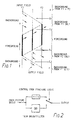
- Figure 1 shows the situation of a foreground object moving upwards and the background moving downwards.
- the technique used detects the cut and paste edges in the picture and applies filtering subject to the probability of the edges being visible i.e. aliases being present.
- the output picture is made from the weighted sum of two input pictures.
- the picture is made primarily from the nearest field in time.
- the nearest field is unlikely to have many positional fractures because the picture elements have not yet moved far.
- the further field is quite likely to have fractures but the contribution from this field is less because it is further away in time.
- the output picture is co-timed with the input picture then there is no fracture in the output picture as the input pictures makes 100% of the output picture. There are, however, lots of fractures in the other picture but that makes 0% of the output.
- Another rule is used to stop the low pass filter being applied to perfectly good output. According to this rule there is a fracture existing in the output picture if there is a fracture in the displacement field belonging to an input picture and the contribution from that picture is more than F% (F may be set to about 20% but this can be optimised for a particular application).
- the low pass filter Since any one may cause a visible fracture the low pass filter is assumed to be necessary.
- the filter itself is a very small aperture and the side effect is quite small but quite effective at breaking up the sharp discontinuities caused by cut and paste.
- a switch signal is derived in the way outlined above and is used to select either sharp unfiltered picture or the softer filtered picture.
- the switch signal along a fracture line is normally only a few pixels wide, say six at the most, so that the area of the picture affected by the airbrush filter is a minimum. It is difficult to see the effect of the filter on picture sharpness because it may affect only two or three samples.
- Figure 2 shows the arrangement of the low-pass filter and switch. A delay to match any delay introduced by the filter is provided in parallel for unfiltered output.
- the system described can be applied to any system which uses motion compensation.
- Figure 3 shows a more sophisticated embodiment of the invention. This embodiment searches for five different types of fracture and performs softening if one of these is detected. The five types are x and y directional fractures in data from a forward projected vector field. x and y fractures in data form a reverse projected vector field. And finally fractures in crossfaded areas of the picture. Thus forward fracture logic, reverse fracture logic, and crossfade fracture logic are shown.
- the forward and reverse projected vector fields are derived as follows. Vectors are assigned to each elementary area of the input fields for forward and reverse projection. These vectors are then assigned to elementary areas of an output field in a shifted vector field by multiplying them by the distance to the output field to give a total displacement which is then added to the base address of the pixel assigned to that vector in the input field.
- the shifted vector field thus comprises a set of unscaled vectors each assigned to an elementary area of the output field.
- the x and y components of a forward projected vector field are each put through 2D differentiating filters 10 and 12 respectively. This generates a signal, in each case, whose magnitude is dependent upon the difference between vectors assigned to adjacent elementary areas (or pixels) of the picture.
- the output of the differentiating filters is then scaled in multipliers 11 and 13 which multiply the differential by the distance of the output field from the input field. This is necessary to determine the size of the fracture. Any sign changes in the differentials are then removed in the modulus detectors 15 and 17.
- a pair of threshold detectors 14 and 16 receive the outputs of these modulus detectors and if the output of either is above a threshold B, i.e. a discontinuity above a predetermined value has been detected, then a control signal is generated at the output of the respective detector.
- the control signals at the outputs of the two detectors are passed to an OR gate 18 which generates an output if a signal is produced by either detector.
- the output of the OR gate then forms one input to an AND gate 20.
- the other input receives the crossfade factor between the input fields. If F1, which is the proportion of the output field generated by the forward projected input field, is greater than 20%, then the AND gate 20 will produce an output labelled F when a discontinuity is detected.
- 2D filters 22 and 24, multipliers 21 and 23, modulus detectors 27 and 29, threshold detectors 26 and 28, an OR gate 30, and an AND gate 32 operate on the backwards projected vector fields.
- the outputs of the differentiating filters 22 and 27 are multiplied by 1 minus distance from the input field.
- F2 the proportion of the output field generated by the backwards projected vector field is 1-CROSSFADE FACTOR.
- the AND gate 32 has an output labelled R which is generated when a discontinuity is detected.
- the multipliers may be omitted by varying the thrssholds of the threshold detectors in dependence on the distance of the output field from the input field and storing a scaled vector in the shifted vector field.
- the signals F, R, and CF all form inputs to an OR gate 38 and the presence of any one of them generates an output which controls a switch 40 to switch an input video signal through an airbrush filter 40. (see fig. 2).
- the 2D differentiating filters used are typically 5-tap filters and give a weighting of 4 to the central pixel and weightings of -1 to each adjacent pixel in the x and y directions.
- a smoothing filter is selected in accordance with the direction of the discontinuity. If a discontinuity only appears in the x direction then smoothing will only be performed in the x direction. Correspondingly a discontinuity in the y direction will be smoothed in the y direction.
- the smoothing filter used can be selected with reference to a look-up table. Alternatively the filter direction could be calculated in dependence on the direction of the fracture detected.
Landscapes
- Engineering & Computer Science (AREA)
- Multimedia (AREA)
- Signal Processing (AREA)
- Studio Circuits (AREA)
- Closed-Circuit Television Systems (AREA)
- Apparatus For Radiation Diagnosis (AREA)
- Ultra Sonic Daignosis Equipment (AREA)
- Image Processing (AREA)
- Image Analysis (AREA)
- Cameras Adapted For Combination With Other Photographic Or Optical Apparatuses (AREA)
- Color Television Image Signal Generators (AREA)
- Lubrication Of Internal Combustion Engines (AREA)
- Picture Signal Circuits (AREA)
- Television Signal Processing For Recording (AREA)
- Photoreceptors In Electrophotography (AREA)
Claims (20)
- Verfahren zur Analyse einer Anzahl von Eingangshalbbildern, das verwendet wird, um ein bewegungskompensiertes, zusammengesetztes Bild, zeitlich beabstandet zu den Eingangshalbbildem, zu erzeugen, welches die Schritte umfaßt: es wird zumindest ein Halbbild von Bewegungsvektoren aus einer Anzahl der Eingangshalbbilder erzeugt, wobei jeder Bewegungsvektor jeweils einem Elementarbereich von zumindest einem der Eingangshalbbilder zugeordnet ist; gekennzeichnet durch durch die Schritte: ein Verschiebungshalbbild von Werten wird durch Projektion der Bewegungsvektoren gemäß dem Wert des jeweiligen Bewegungsvektors und gemäß dem zeitlichen Abstand zwischen dem oder dem jeweiligen Eingangshalbbild und dem zusammengesetzten Bild erzeugt; und Bereiche in dem Verschiebungshalbbild werden festgestellt, in denen im Vergleich zu benachbarten Bereichen Wechsel bzw. Übergänge in den Verschiebungshalbbildwerten vorliegen.
- Verfahren nach Anspruch 1, bei dem die festgestellten Wechsel- bzw. Übergangsbereiche diejenigen sind, für die der Wechsel bzw. Übergang einen vorbestimmten Schwellenwert überschreitet.
- Verfahren nach Anspruch 1 oder 2, bei dem die Werte des Verschiebungshalbbildes Vektoren sind.
- Verfahren nach einem der vorhergehenden Ansprüche zur Erzeugung eines zusammengesetzten Ausgangsbildes zwischen einem ersten Halbbild und einem zweiten Halbbild, in dem das erste Halbbild vorwärts projiziert und das zweite Halbbild rückwärts projiziert wird, welches Verfahren femer den Schritt umfaßt, daß ein Überblendfaktor erzeugt wird, der die relativen Anteile der ersten und zweiten Halbbilder darstellt, die bei der Erzeugung des Ausgangsbildes verwendet werden sollen.
- Verfahren nach Anspruch 4, welches femer der Schritt umfaßt, daß Bereiche festgestellt werden, in denen Änderungen im Überblendfaktor größer als ein gegebener Schwellenwert sind.
- Verfahren nach Anspruch 5, bei dem für Bereiche festgestellt wird, daß diese Diskontinuitäten aufweisen, falls:(1) ein Wechsel bzw. Übergang in dem von dem ersten Eingangshalbbild projizierten Verschiebungshalbbild festgestellt wird und der Beitrag des ersten Eingangshalbbildes zum Ausgangsbild oberhalb eines ersten vorbestimmten Schwellenwertes liegt; oder(2) ein Übergang in dem von dem zweiten Eingangshalbbild projizierten Verschiebungshalbbild festgestellt wird und der Beitrag des zweiten Eingangshalbbildes zum Ausgangsbild oberhalb eines zweiten vorbestimmten Schwellenwertes liegt; oder(3) eine Änderung im Überblendfaktor festgestellt wird, die größer als ein gegebener Schwellenwert ist.
- Verfahren zur Verarbeitung eines bewegungskompensierten, zusammengesetzten Bildes, das aus einer Anzahl von Eingangshalbbildem erzeugt wurde, welches Verfahren die Schritte umfaßt: ein Verfahren nach einem der vorhergehenden Ansprüche wird durchgeführt; und ein Glättungsfilter wird auf Bereiche des zusammengesetzten Bildes angewendet, die den festgestellten Bereichen entsprechen.
- Verfahren nach Anspruch 7, bei dem der Glättungsfilter nur auf einen Wechsel bzw. Übergang angewendet wird, der von solch einem Eingangshalbbild festgestellt wurde, das mit einem größeren als dem vorbestimmten Anteil des zusammengesetzten Bildes beiträgt.
- Verfahren nach Anspruch 7 oder 8, bei dem die Richtung eines Wechsels bzw. Übergangs festgestellt wird und der Glättungsfilter in Abhängigkeit von der Richtung des Wechsels bzw. Überganges angelegt wird.
- Verfahren nach Anspruch 9, bei dem der Glättungsfilter durch Verweis auf eine Nachschlagetabelle ausgewählt wird.
- Verfahren nach Anspruch 9, bei dem die Filterrichtung in Abhängigkeit von der Richtung des Wechsels bzw. Übergangs berechnet wird.
- Verfahren nach einem der Ansprüche 7 bis 11, bei dem der Glättungsfilter einen Tiefpaßfilter umfaßt.
- Verfahren nach einem der vorhergehenden Ansprüche, bei dem ein 2D differenzierender Filter verwendet wird, um die Wechsel bzw. Übergänge festzustellen.
- Vorrichtung zur Analyse einer Anzahl von Eingangshalbbildem, welche Vorrichtung verwendet wird, um ein bewegungskompensiertes, zusammengesetztes Bild, zeitlich beabstandet zu den Eingangshalbbildem, zu erzeugen, welche Vorrichtung umfaßt: Mittel zur Erzeugung von zumindest einem Halbbild von Bewegungsvektoren aus einer Anzahl der Eingangshalbbilder, wobei jeder Bewegungsvektor einem jeweiligen Elementarbereich von zumindest einem der Eingangshalbbilder zugeordnet ist; gekennzeichnet durch: Mittel zur Erzeugung eines Verschiebungshalbbildes von Werten durch Projektion der Bewegungsvektoren, jeweils entsprechend dem Wert des jeweiligen Bewegungsvektors und entsprechend dem zeitlichen Abstand zwischen dem oder dem jeweiligen Eingangshalbbild und dem zusammengesetzten Bild; und Mittel (10 bis 32, 38) zum Feststellen von Bereichen in dem Verschiebungshalbbild, in denen im Vergleich zu benachbarten Bereichen Wechsel bzw. Übergänge in den Verschiebungshalbbildwerten vorliegen.
- Vorrichtung nach Anspruch 14, bei der das Mittel zur Erzeugung des Verschiebungshalbbildes betreibbar ist, um solche Werte zu erzeugen, die Vektoren darstellen.
- Vorrichtung nach Anspruch 14 oder 15, welche ausgelegt ist, um ein Steuersignal zu erzeugen, das eine projizierte Diskontinuität in dem Ausgangsbild anzeigt.
- Vorrichtung nach Anspruch 16, bei der das Feststellungsmittel umfaßt: einen Filter (10, 12, 22, 24) zum Differenzieren des Verschiebungshalbbildes; und Mittel (14 bis 20, 26 bis 32, 38) zum Erzeugen des Steuersignals, wenn ein Ausgangssignal des differenzierenden Filters einen vorbestimmten Schwellenwert überschreitet.
- Vorrichtung zur Verarbeitung eines bewegungskompensierten, zusammengesetzten Bildes, das aus einer Anzahl von Eingangshalbbildern erzeugt wurde, welche Vorrichtung umfaßt: eine Vorrichtung, wie in einem der Ansprüche 16 oder 17 beansprucht; sowie Mittel, die auf das Steuersignal ansprechen, um einen Glättungsfilter auf das zusammengesetzte Bild anzuwenden.
- Vorrichtung nach einem der Ansprüche 14 bis 18 zur Erzeugung eines zusammengesetzten Ausgangsbildes zwischen einem ersten Halbbild und einem zweiten Halbbild durch Vorwärtsprojektion des ersten Halbbildes und Rückwärtsprojektion des zweiten Halbbildes, welche Vorrichtung außerdem ein Mittel zur Erzeugung eines Überblendfaktors umfaßt, welcher den relativen Anteil des ersten und zweiten Halbbildes darstellt, der bei der Erzeugung des Ausgangsbildes verwendet werden soll.
- Vorrichtung nach Anspruch 19, wenn dieser von Anspruch 16, 17 oder 18 abhängig ist, bei welcher Vorrichtung das Steuersignal erzeugt wird, wenn festgestellt wird:(1) ein Wechsel bzw. Übergang in dem von dem ersten Eingangshalbbild projizierten Verschiebungshalbbild, falls der Beitrag des ersten Eingangshalbbildes zum Ausgangsbild oberhalb eines ersten vorbestimmten Schwellenwertes liegt; oder(2) ein Übergang in dem von dem zweiten Eingangshalbbild projizierten Verschiebungshalbbild, falls der Beitrag des zweiten Eingangshalbbildes zum Ausgangsbild oberhalb eines zweiten vorbestimmten Schwellenwertes liegt; oder(3) eine Änderung in dem Überblendfaktor, größer als ein gegebener Schwellenwert.
Applications Claiming Priority (3)
| Application Number | Priority Date | Filing Date | Title |
|---|---|---|---|
| GB929204115A GB9204115D0 (en) | 1992-02-26 | 1992-02-26 | Video image processing |
| GB9204115 | 1992-02-26 | ||
| PCT/GB1993/000402 WO1993017520A1 (en) | 1992-02-26 | 1993-02-26 | Video image processing |
Publications (2)
| Publication Number | Publication Date |
|---|---|
| EP0628233A1 EP0628233A1 (de) | 1994-12-14 |
| EP0628233B1 true EP0628233B1 (de) | 1998-06-17 |
Family
ID=10711091
Family Applications (1)
| Application Number | Title | Priority Date | Filing Date |
|---|---|---|---|
| EP93905479A Expired - Lifetime EP0628233B1 (de) | 1992-02-26 | 1993-02-26 | Videobildverarbeitung |
Country Status (13)
| Country | Link |
|---|---|
| US (1) | US5633956A (de) |
| EP (1) | EP0628233B1 (de) |
| JP (1) | JPH07504540A (de) |
| CN (1) | CN1076070A (de) |
| AT (1) | ATE167604T1 (de) |
| AU (1) | AU3639093A (de) |
| CA (1) | CA2130817A1 (de) |
| DE (1) | DE69319227T2 (de) |
| DK (1) | DK0628233T3 (de) |
| FI (1) | FI943913A7 (de) |
| GB (1) | GB9204115D0 (de) |
| NO (1) | NO943153L (de) |
| WO (1) | WO1993017520A1 (de) |
Families Citing this family (15)
| Publication number | Priority date | Publication date | Assignee | Title |
|---|---|---|---|---|
| KR0134325B1 (ko) * | 1993-12-16 | 1998-04-23 | 배순훈 | 영상 데이타 전처리 필터 |
| US6340994B1 (en) | 1998-08-12 | 2002-01-22 | Pixonics, Llc | System and method for using temporal gamma and reverse super-resolution to process images for use in digital display systems |
| WO2000010326A2 (en) * | 1998-08-12 | 2000-02-24 | Focus Enhancements, Inc. | Two-dimensional adjustable flicker filter |
| US6782132B1 (en) | 1998-08-12 | 2004-08-24 | Pixonics, Inc. | Video coding and reconstruction apparatus and methods |
| EP1048170A1 (de) | 1998-08-21 | 2000-11-02 | Koninklijke Philips Electronics N.V. | Lokalisierung von problematischen bereichen in einem bildsignal |
| US6466624B1 (en) | 1998-10-28 | 2002-10-15 | Pixonics, Llc | Video decoder with bit stream based enhancements |
| WO2001045036A1 (en) * | 1999-12-14 | 2001-06-21 | Dynapel Systems, Inc. | Slow motion system |
| KR100904340B1 (ko) * | 2001-06-15 | 2009-06-23 | 소니 가부시끼 가이샤 | 화상 처리 장치 및 방법과 촬상 장치 |
| JP4596223B2 (ja) * | 2001-06-27 | 2010-12-08 | ソニー株式会社 | 画像処理装置および方法、記録媒体、並びにプログラム |
| US7266150B2 (en) * | 2001-07-11 | 2007-09-04 | Dolby Laboratories, Inc. | Interpolation of video compression frames |
| CN1922873A (zh) * | 2004-02-23 | 2007-02-28 | 皇家飞利浦电子股份有限公司 | 通过合并图像的内插与外推来减少图像信号的扫描速率变换中的赝像 |
| US9659353B2 (en) * | 2010-03-01 | 2017-05-23 | Stmicroelectronics, Inc. | Object speed weighted motion compensated interpolation |
| CN116708827A (zh) * | 2019-02-28 | 2023-09-05 | 华为技术有限公司 | 编码器、解码器及相应的帧间预测方法 |
| US11936992B2 (en) * | 2022-01-18 | 2024-03-19 | Apple Inc. | Multi-mode demosaicing for raw image data |
| US12477120B2 (en) * | 2022-10-17 | 2025-11-18 | Alibaba Damo (Hangzhou) Technology Co., Ltd. | Keypoints based video compression |
Family Cites Families (5)
| Publication number | Priority date | Publication date | Assignee | Title |
|---|---|---|---|---|
| FR2599205B1 (fr) * | 1981-11-27 | 1990-08-24 | Thomson Csf | Procede recursif de caracterisation de zones isotropes dans une image video; dispositif detecteur de mouvement et detecteur de bruit dans une sequence d'images |
| DE3408061A1 (de) * | 1984-03-05 | 1985-09-05 | ANT Nachrichtentechnik GmbH, 7150 Backnang | Verfahren zur bewegungsadaptiven interpolation von fernsehbildsequenzen und anwendungen dieses verfahrens |
| EP0294961B1 (de) * | 1987-06-09 | 1994-10-12 | Sony Corporation | Auswahl eines Bewegungsvektors in Fernsehbildern |
| EP0337565B1 (de) * | 1988-04-15 | 1993-03-10 | Laboratoires D'electronique Philips | Einrichtung zur Kodierung von Signalen, die eine Folge von Bildern darstellen und Übertragungssystem von Fernsehbildern mit hoher Auflösung mit einer solchen Einrichtung |
| US5134480A (en) * | 1990-08-31 | 1992-07-28 | The Trustees Of Columbia University In The City Of New York | Time-recursive deinterlace processing for television-type signals |
-
1992
- 1992-02-26 GB GB929204115A patent/GB9204115D0/en active Pending
-
1993
- 1993-02-26 CN CN93102006.9A patent/CN1076070A/zh active Pending
- 1993-02-26 US US08/290,968 patent/US5633956A/en not_active Expired - Lifetime
- 1993-02-26 FI FI943913A patent/FI943913A7/fi unknown
- 1993-02-26 EP EP93905479A patent/EP0628233B1/de not_active Expired - Lifetime
- 1993-02-26 AT AT93905479T patent/ATE167604T1/de not_active IP Right Cessation
- 1993-02-26 AU AU36390/93A patent/AU3639093A/en not_active Withdrawn
- 1993-02-26 JP JP5514671A patent/JPH07504540A/ja active Pending
- 1993-02-26 CA CA002130817A patent/CA2130817A1/en not_active Abandoned
- 1993-02-26 WO PCT/GB1993/000402 patent/WO1993017520A1/en not_active Ceased
- 1993-02-26 DE DE69319227T patent/DE69319227T2/de not_active Expired - Fee Related
- 1993-02-26 DK DK93905479T patent/DK0628233T3/da active
-
1994
- 1994-08-25 NO NO943153A patent/NO943153L/no unknown
Also Published As
| Publication number | Publication date |
|---|---|
| CA2130817A1 (en) | 1993-09-02 |
| US5633956A (en) | 1997-05-27 |
| NO943153D0 (no) | 1994-08-25 |
| FI943913A0 (fi) | 1994-08-25 |
| DE69319227D1 (de) | 1998-07-23 |
| FI943913L (fi) | 1994-10-20 |
| ATE167604T1 (de) | 1998-07-15 |
| WO1993017520A1 (en) | 1993-09-02 |
| FI943913A7 (fi) | 1994-10-20 |
| DE69319227T2 (de) | 1998-10-22 |
| DK0628233T3 (da) | 1999-03-01 |
| CN1076070A (zh) | 1993-09-08 |
| EP0628233A1 (de) | 1994-12-14 |
| JPH07504540A (ja) | 1995-05-18 |
| AU3639093A (en) | 1993-09-13 |
| GB9204115D0 (en) | 1992-04-08 |
| NO943153L (no) | 1994-10-26 |
Similar Documents
| Publication | Publication Date | Title |
|---|---|---|
| EP0628233B1 (de) | Videobildverarbeitung | |
| US7406208B2 (en) | Edge enhancement process and system | |
| US8358878B2 (en) | Method and apparatus for interpolating an image | |
| KR930701888A (ko) | 비디오 영상 프로세싱 방법 및 장치 | |
| US5606631A (en) | Method for detecting and removing errors exceeding a specific contrast in digital video signals | |
| JP2007502454A (ja) | マルチビュー画像の生成 | |
| JPH02294170A (ja) | 反復映像にじみ効果装置 | |
| EP1042919B1 (de) | Verfahren und vorrichtung zur erzeugung eines stehbildes | |
| CN102918830A (zh) | 图像处理装置和方法、图像显示装置和方法 | |
| WO2001043069A2 (en) | Method and apparatus for past and future motion classification | |
| JP2001061152A (ja) | 動き検出方法および動き検出装置 | |
| GB2184628A (en) | Video signal processing | |
| KR100311472B1 (ko) | 영상 데이터 보간 장치 및 방법 | |
| JPH09224249A (ja) | 動きベクトル検出装置 | |
| GB2245795A (en) | Generating convoluted digital video signals | |
| Moriyama et al. | Edge-Enhanced Deformable Attention Network for Video Deblurring | |
| JPH07336563A (ja) | 画像フィルタリング方法及び画像フィルタリング装置 | |
| Thomas | Motion estimation and its application to HDTV transmission and up-conversion using DATV | |
| KR930011140B1 (ko) | 휘도/색 신호 분리회로 및 방법 | |
| JPS59210773A (ja) | テレビジヨン信号処理回路 | |
| GB2361372A (en) | Motion compensated standards conversion | |
| JPH0646298A (ja) | 映像信号の雑音除去装置およびこれに用いる動き検出回路 | |
| JPH0429488A (ja) | 動き検出回路およびこの動き検出回路を用いた画像処理装置 | |
| JPH03256490A (ja) | 動き検出回路および輝度信号色信号分離回路 | |
| US20030165195A1 (en) | Block based video processing |
Legal Events
| Date | Code | Title | Description |
|---|---|---|---|
| PUAI | Public reference made under article 153(3) epc to a published international application that has entered the european phase |
Free format text: ORIGINAL CODE: 0009012 |
|
| 17P | Request for examination filed |
Effective date: 19940831 |
|
| AK | Designated contracting states |
Kind code of ref document: A1 Designated state(s): AT DE DK FR GB IT NL SE |
|
| 17Q | First examination report despatched |
Effective date: 19961121 |
|
| GRAG | Despatch of communication of intention to grant |
Free format text: ORIGINAL CODE: EPIDOS AGRA |
|
| GRAG | Despatch of communication of intention to grant |
Free format text: ORIGINAL CODE: EPIDOS AGRA |
|
| GRAH | Despatch of communication of intention to grant a patent |
Free format text: ORIGINAL CODE: EPIDOS IGRA |
|
| GRAH | Despatch of communication of intention to grant a patent |
Free format text: ORIGINAL CODE: EPIDOS IGRA |
|
| GRAA | (expected) grant |
Free format text: ORIGINAL CODE: 0009210 |
|
| AK | Designated contracting states |
Kind code of ref document: B1 Designated state(s): AT DE DK FR GB IT NL SE |
|
| REF | Corresponds to: |
Ref document number: 167604 Country of ref document: AT Date of ref document: 19980715 Kind code of ref document: T |
|
| ITF | It: translation for a ep patent filed | ||
| REF | Corresponds to: |
Ref document number: 69319227 Country of ref document: DE Date of ref document: 19980723 |
|
| ET | Fr: translation filed | ||
| PGFP | Annual fee paid to national office [announced via postgrant information from national office to epo] |
Ref country code: AT Payment date: 19990224 Year of fee payment: 7 |
|
| PG25 | Lapsed in a contracting state [announced via postgrant information from national office to epo] |
Ref country code: SE Free format text: LAPSE BECAUSE OF NON-PAYMENT OF DUE FEES Effective date: 19990227 |
|
| REG | Reference to a national code |
Ref country code: DK Ref legal event code: T3 |
|
| PG25 | Lapsed in a contracting state [announced via postgrant information from national office to epo] |
Ref country code: DK Free format text: LAPSE BECAUSE OF NON-PAYMENT OF DUE FEES Effective date: 19990331 |
|
| PLBE | No opposition filed within time limit |
Free format text: ORIGINAL CODE: 0009261 |
|
| STAA | Information on the status of an ep patent application or granted ep patent |
Free format text: STATUS: NO OPPOSITION FILED WITHIN TIME LIMIT |
|
| 26N | No opposition filed | ||
| EUG | Se: european patent has lapsed |
Ref document number: 93905479.7 |
|
| REG | Reference to a national code |
Ref country code: DK Ref legal event code: EBP |
|
| PG25 | Lapsed in a contracting state [announced via postgrant information from national office to epo] |
Ref country code: AT Free format text: LAPSE BECAUSE OF NON-PAYMENT OF DUE FEES Effective date: 20000226 |
|
| REG | Reference to a national code |
Ref country code: GB Ref legal event code: IF02 |
|
| PGFP | Annual fee paid to national office [announced via postgrant information from national office to epo] |
Ref country code: NL Payment date: 20090224 Year of fee payment: 17 Ref country code: DE Payment date: 20090219 Year of fee payment: 17 |
|
| PGFP | Annual fee paid to national office [announced via postgrant information from national office to epo] |
Ref country code: GB Payment date: 20090126 Year of fee payment: 17 |
|
| PGFP | Annual fee paid to national office [announced via postgrant information from national office to epo] |
Ref country code: IT Payment date: 20090212 Year of fee payment: 17 |
|
| PGFP | Annual fee paid to national office [announced via postgrant information from national office to epo] |
Ref country code: FR Payment date: 20090128 Year of fee payment: 17 |
|
| REG | Reference to a national code |
Ref country code: NL Ref legal event code: V1 Effective date: 20100901 |
|
| GBPC | Gb: european patent ceased through non-payment of renewal fee |
Effective date: 20100226 |
|
| REG | Reference to a national code |
Ref country code: FR Ref legal event code: ST Effective date: 20101029 |
|
| PG25 | Lapsed in a contracting state [announced via postgrant information from national office to epo] |
Ref country code: NL Free format text: LAPSE BECAUSE OF NON-PAYMENT OF DUE FEES Effective date: 20100901 Ref country code: FR Free format text: LAPSE BECAUSE OF NON-PAYMENT OF DUE FEES Effective date: 20100301 |
|
| PG25 | Lapsed in a contracting state [announced via postgrant information from national office to epo] |
Ref country code: DE Free format text: LAPSE BECAUSE OF NON-PAYMENT OF DUE FEES Effective date: 20100901 |
|
| PG25 | Lapsed in a contracting state [announced via postgrant information from national office to epo] |
Ref country code: IT Free format text: LAPSE BECAUSE OF NON-PAYMENT OF DUE FEES Effective date: 20100226 Ref country code: GB Free format text: LAPSE BECAUSE OF NON-PAYMENT OF DUE FEES Effective date: 20100226 |