EP0628143B1 - Channel system with a cross-section with rounded corners - Google Patents
Channel system with a cross-section with rounded corners Download PDFInfo
- Publication number
- EP0628143B1 EP0628143B1 EP93904039A EP93904039A EP0628143B1 EP 0628143 B1 EP0628143 B1 EP 0628143B1 EP 93904039 A EP93904039 A EP 93904039A EP 93904039 A EP93904039 A EP 93904039A EP 0628143 B1 EP0628143 B1 EP 0628143B1
- Authority
- EP
- European Patent Office
- Prior art keywords
- basic
- basic part
- channel
- channel system
- parts
- Prior art date
- Legal status (The legal status is an assumption and is not a legal conclusion. Google has not performed a legal analysis and makes no representation as to the accuracy of the status listed.)
- Expired - Lifetime
Links
Images


Classifications
-
- F—MECHANICAL ENGINEERING; LIGHTING; HEATING; WEAPONS; BLASTING
- F16—ENGINEERING ELEMENTS AND UNITS; GENERAL MEASURES FOR PRODUCING AND MAINTAINING EFFECTIVE FUNCTIONING OF MACHINES OR INSTALLATIONS; THERMAL INSULATION IN GENERAL
- F16L—PIPES; JOINTS OR FITTINGS FOR PIPES; SUPPORTS FOR PIPES, CABLES OR PROTECTIVE TUBING; MEANS FOR THERMAL INSULATION IN GENERAL
- F16L9/00—Rigid pipes
- F16L9/003—Rigid pipes with a rectangular cross-section
Definitions
- the invention relates to a channel system with a cross-section with rounded corners, comprising various elements, such as straight, branch, corner, reducing fittings and/or the like with planar and arched, such as convex, concave or corresponding walls, and which elements are manufactured of a material preferably with thin walls, such as sheet metal, plastic or the like.
- a cross-section with rounded corners at least part of the elements of the channel system are formed by using joining arrangements to connect at least arched wall parts with each other, preferably substantially the edges thereof, wherein the elements connected with each other form a flow or wiring channel or the like.
- channels with a cross-section with rounded corners are more advantageous for flowing than acute-angled, e.g. rectangular or quadratic channels.
- acute-angled e.g. rectangular or quadratic channels.
- the flow is naturally not evenly distributed onto all parts of the wall, as compared with a channel with rounded corners, and turbulence is induced by acute angles.
- impurities are gradually accumulated in the ducts.
- channels with rounded corners are spiral tubes which are manufactured for each standardized tube size.
- the various branch, corner, reducing and corresponding fittings are manufactured by applying ordinary sheet working techniques.
- the manufacture of the said elements requires good professional skills and/or specially tailored equipment, such as moulds, templates or the like.
- tools for each size must be used.
- such channel systems made of spiral tubes usually have a clumsy general appearance due to elements manufactured with most various techniques and skills.
- GB-1,301,858 and GB-1,552,916 disclose elements formed by planar parts joined together, applicable for use in a channel system with a cross-section with sharp edges.
- GB-1,301,858 presents a fireproof channel element, the wall being formed by flat plates joined together by corrosion-resistant connecting means fixed at the inner edges and tne outer surfaces of the joints being welded.
- GB-1,552,916 presents a solution for forming the walls of an element of flat plates notched and bent into a right angle, which are fixed to each other by U-shaped connecting means and support frames.
- the solutions of both publications are only applicable for manufacturing elements with a cross-section with sharp edges. Further, the application requires precise dimensioning of the wall parts and the use of particular connecting means. Consequently, the said solutions are demanding with respect to both their manufacturing - to secure sufficient compatibility of elements - and their installation - because several operations are needed.
- Finnish Patent Application No. 497/71 presents a method and device for connecting elements in ventilation systems with high requirements for tightness.
- the method presented in the publication can also be applied for manufacturing elements of a channel system with a cross-section with rounded corners.
- the invention of the publication relates to manufacturing elements of separate wall surfaces, the edges being equipped with joint arrangements.
- the joint arrangements are formed by a U-shaped joint part at the edge of another wall surface, the edge of the opposite wall surface being placed therebetween.
- the publication discloses applications with a cross-section with rounded corners of a straight element, a T-branch and an angle of 90°, each being formed by two arched wall surfaces placed against each other.
- the joint solution presented in the publication is useful in principle, but it does not, however, offer a comprehensive solution for manufacturing elements with different shapes and sizes.
- the most important advantages of the channel system of the invention are the simplicity and uniformity of the basic parts used therein, whereby the entire channel system with elements of different sizes and shapes can be composed of the same basic parts. There is thus no need e.g. to manufacture separate tools to correspond to each element size or shape as in the present methods.
- the channel system of the invention is thus also uniform in appearance, whereby it has, most preferably, rounded corners in all elements.
- the invention makes it possible to manufacture elements of the channel system by a simple set of tools, because a uniform channel system of the invention can be composed of basic parts having the same basic shapes.
- the elements of different sizes and shapes are formed simply by combining planar basic parts and arched basic parts, the latter being most preferably made in only three shapes.
- the application of the method does not require difficult or additional operations, and all elements can be assembled and joined to each other by simple joining arrangements suitable for each purpose.
- Figs. 1 to 4 are examples of a channel system of the invention having a cross-section with rounded corners and including different elements, such as straight, branch, corner, reducing fittings and/or the like.
- the elements have planar 1 and arched 2, such as convex, concave or corresponding walls, and they are manufactured of a material preferably with thin walls, such as sheet metal, plastic or the like.
- the elements of the channel system are formed by connecting at least arched wall parts 2 by their edges with each other using joining arrangements, wherein the elements connected with each other form a flow or wiring channel or the like.
- the elements of the channel system having different sizes and/or shapes according to the invention are formed by combining basic parts 1a, 2a, 2b, 2c forming planar 1 and arched 2 wall parts.
- FIG. 1a A closed channel with a cross-section with rounded corners is shown in Fig. 1a and in an exploded view in Fig. 1b.
- the planar wall parts 1 of the channel are formed by first basic parts which in this embodiment are rectangular flat plates 1a.
- the arched wall parts 2 are formed by second basic parts 2a which extend in the longitudinal direction s and are arched in the transverse direction, thus forming the rounded corners of the channel as their longitudinal edges are attached to plates 1a.
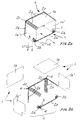
- a corner piece in a 90° angle is shown in Fig. 2a and in an exploded view in Fig. 2b.
- the edges of the internal angle 3 of the piece are formed by third basic parts 2b joining the two longitudinal directions s1, s2 in an arch and arranged in the transverse direction in an arch.
- These third basic parts 2b are connected at their first edges to a second basic part 2a joining them and at their second edges to side plates 1a'.
- edges of the external angle 4 of the corner piece are formed by fourth basic parts 2c arranged to be continuously arched and connected at their edges to second basic parts 2a.
- the upper and back walls of the piece are formed by flat plates 1a joined with second basic parts.
- the arches of the edges of second 2a, third 2b and fourth 2c basic parts forming arched wall parts 2, to be connected with each other are formed using a substantially equal radius R of curvature.
- each third basic part 2b to be joined with a side plate la' is arranged to join the plane t defined by the side plate 1a' in an arch. Further, the said edge is formed by two flat edge parts in angles deviating from each other in the said plane t.
- the angle between the longitudinal directions sl, s2 being 90° in the case in question, it is most advantageous to elect the angle between the straight edge parts also a right angle.
- side plates la' by only deleting the rectangular pieces from the corners.
- the second basic part 2a is preferably formed by 1/4 of a cylindrical surface and the fourth basic part 2c substantially of 1/8 of a spherical surface, correspondingly.
- Figure 3 shows a corner piece corresponding to the Figs. 2a, 2b, the longitudinal directions deviating in an angle of 45°.
- the fourth basic part 2c' is formed by 1/16 of a spherical surface, whereby the third basic part 2b' and the second basic part 2a' are arranged in an angle of 45° correspondingly.
- Both side plates la" are formed of hexagonal plates which are symmetrical in relation to their central line K.
- Figure 4 shows a channel system with a uniform appearance, manufactured by the method of the invention.
- the method of the invention can be used for manufacturing both closed channels and partly open channels.
- Open channels can be used, as presented, as wiring channels or cover plates.
- the invention is thus used to form elements with different shapes by combining planar and arched wall parts suitably with each other in order to manufacture elements with different shapes.
- corresponding elements with different sizes in the channel system are manufactured by using the same basic parts, whereby the dimensions, such as the area and length, of the first and second basic parts are changed correspondingly.
- the corner piece shown in Figs. 2a, 2b can be simply modified into a T-piece open in three directions.
- the basic parts can naturally be connected to each other by a variety of joining arrangements depending on the material used and the purpose of the channel in question.
- the basic parts can be formed e.g. by a joining principle of the type mentioned in the beginning of the description above.
- the joining arrangements can be arranged to be disassembled e.g. for forming various cover plates of temporary art.
- the channel system of the invention can be used in a variety of applications, manufactured of a variety of materials and by a variety of techniques.
Abstract
Description
- The invention relates to a channel system with a cross-section with rounded corners, comprising various elements, such as straight, branch, corner, reducing fittings and/or the like with planar and arched, such as convex, concave or corresponding walls, and which elements are manufactured of a material preferably with thin walls, such as sheet metal, plastic or the like. For achieving a cross-section with rounded corners, at least part of the elements of the channel system are formed by using joining arrangements to connect at least arched wall parts with each other, preferably substantially the edges thereof, wherein the elements connected with each other form a flow or wiring channel or the like.
- Particularly as flow channels, channels with a cross-section with rounded corners are more advantageous for flowing than acute-angled, e.g. rectangular or quadratic channels. In a channel with acute angles, the flow is naturally not evenly distributed onto all parts of the wall, as compared with a channel with rounded corners, and turbulence is induced by acute angles. Thus for example in ordinary ventilation systems, impurities are gradually accumulated in the ducts.
- Commonly used channels with rounded corners are spiral tubes which are manufactured for each standardized tube size. In a channel system made of spiral tubes, the various branch, corner, reducing and corresponding fittings are manufactured by applying ordinary sheet working techniques. Thus the manufacture of the said elements requires good professional skills and/or specially tailored equipment, such as moulds, templates or the like. For reasons of manufacturing techniques, it is usually necessary to provide certain elements of a channel system having a cross-section with otherwise rounded corners with partly sharp edges, whereby it is not possible to maintain the advantageous cross-section with rounded corners in all parts. Naturally, for different elements needed for each tube size, tools for each size must be used. In practice, such channel systems made of spiral tubes usually have a clumsy general appearance due to elements manufactured with most various techniques and skills.
- The publications GB-1,301,858 and GB-1,552,916 disclose elements formed by planar parts joined together, applicable for use in a channel system with a cross-section with sharp edges. GB-1,301,858 presents a fireproof channel element, the wall being formed by flat plates joined together by corrosion-resistant connecting means fixed at the inner edges and tne outer surfaces of the joints being welded. GB-1,552,916 presents a solution for forming the walls of an element of flat plates notched and bent into a right angle, which are fixed to each other by U-shaped connecting means and support frames. The solutions of both publications are only applicable for manufacturing elements with a cross-section with sharp edges. Further, the application requires precise dimensioning of the wall parts and the use of particular connecting means. Consequently, the said solutions are demanding with respect to both their manufacturing - to secure sufficient compatibility of elements - and their installation - because several operations are needed.
- Finnish Patent Application No. 497/71 presents a method and device for connecting elements in ventilation systems with high requirements for tightness. The method presented in the publication can also be applied for manufacturing elements of a channel system with a cross-section with rounded corners. The invention of the publication relates to manufacturing elements of separate wall surfaces, the edges being equipped with joint arrangements. The joint arrangements are formed by a U-shaped joint part at the edge of another wall surface, the edge of the opposite wall surface being placed therebetween. The publication discloses applications with a cross-section with rounded corners of a straight element, a T-branch and an angle of 90°, each being formed by two arched wall surfaces placed against each other. The joint solution presented in the publication is useful in principle, but it does not, however, offer a comprehensive solution for manufacturing elements with different shapes and sizes.
- Consequently, it is not possible to manufacture different parts of a channel system by present techniques in a way that all parts of the channel system be based on a cross-sectional shape with rounded corners. Thus, for channel systems presently manufactured, combinations must usually be made of both rounded and angulated components, whereby the whole is unsatisfactory in appearance. Aiming at a uniform appearance, the costs of manufacturing rise onto an extremely high level when present solutions are applied, because separate tools are needed for each size and shape.
- An example of a modular channel system corresponding to the preamble of
claim 1 is known from document DE-A- 2 003 139. - It is an aim of the channel system with a cross-section with rounded corners according to the invention to achieve a decisive improvement to the disadvantages presented above and thus to improve the state of prior art in the field substantially. For achieving this aim, the channel system with a cross-section with rounded corners according to the invention is defined in
claim 1. - The most important advantages of the channel system of the invention are the simplicity and uniformity of the basic parts used therein, whereby the entire channel system with elements of different sizes and shapes can be composed of the same basic parts. There is thus no need e.g. to manufacture separate tools to correspond to each element size or shape as in the present methods. The channel system of the invention is thus also uniform in appearance, whereby it has, most preferably, rounded corners in all elements.
- Advantageous embodiments of the channel system of the invention are presented in the dependent claims.
- The invention makes it possible to manufacture elements of the channel system by a simple set of tools, because a uniform channel system of the invention can be composed of basic parts having the same basic shapes. The elements of different sizes and shapes are formed simply by combining planar basic parts and arched basic parts, the latter being most preferably made in only three shapes. The application of the method does not require difficult or additional operations, and all elements can be assembled and joined to each other by simple joining arrangements suitable for each purpose.
- In the following description, the invention is illustrated in detail with reference to the appended drawings. In the drawings,
- Fig. 1a
- shows a sample of a straight element of a channel system according to the invention,
- Fig. 1b
- is an explosion view of the element shown in Fig. 1a,
- Fig. 2a
- shows a corner piece in a 90° angle,
- Fig. 2b
- is a partial explosion view of the corner fitting shown in Fig. 2a,
- Fig. 3
- shows a corner piece in a 45° angle, and
- Fig. 4
- shows a channel system with a uniform appearance, formed by a channel system of the invention.
- The embodiments shown in Figs. 1 to 4 are examples of a channel system of the invention having a cross-section with rounded corners and including different elements, such as straight, branch, corner, reducing fittings and/or the like. The elements have planar 1 and arched 2, such as convex, concave or corresponding walls, and they are manufactured of a material preferably with thin walls, such as sheet metal, plastic or the like. For achieving a cross-section with rounded corners, the elements of the channel system are formed by connecting at least
arched wall parts 2 by their edges with each other using joining arrangements, wherein the elements connected with each other form a flow or wiring channel or the like. The elements of the channel system having different sizes and/or shapes according to the invention are formed by combiningbasic parts - A closed channel with a cross-section with rounded corners is shown in Fig. 1a and in an exploded view in Fig. 1b. The
planar wall parts 1 of the channel are formed by first basic parts which in this embodiment are rectangularflat plates 1a. Thearched wall parts 2 are formed by secondbasic parts 2a which extend in the longitudinal direction s and are arched in the transverse direction, thus forming the rounded corners of the channel as their longitudinal edges are attached toplates 1a. - A corner piece in a 90° angle is shown in Fig. 2a and in an exploded view in Fig. 2b. The edges of the
internal angle 3 of the piece are formed by third basic parts 2b joining the two longitudinal directions s1, s2 in an arch and arranged in the transverse direction in an arch. These third basic parts 2b are connected at their first edges to a secondbasic part 2a joining them and at their second edges toside plates 1a'. - Further, the edges of the
external angle 4 of the corner piece are formed by fourthbasic parts 2c arranged to be continuously arched and connected at their edges to secondbasic parts 2a. The upper and back walls of the piece are formed byflat plates 1a joined with second basic parts. - For achieving an advantageous assembly of a channel system according to the invention, the arches of the edges of second 2a, third 2b and fourth 2c basic parts forming
arched wall parts 2, to be connected with each other, are formed using a substantially equal radius R of curvature. - As shown in Figs. 2a and 2b, one edge of each third basic part 2b to be joined with a side plate la' is arranged to join the plane t defined by the
side plate 1a' in an arch. Further, the said edge is formed by two flat edge parts in angles deviating from each other in the said plane t. The angle between the longitudinal directions sl, s2 being 90° in the case in question, it is most advantageous to elect the angle between the straight edge parts also a right angle. Thus it is also simple to manufacture side plates la' by only deleting the rectangular pieces from the corners. - In the embodiments presented, the second
basic part 2a is preferably formed by 1/4 of a cylindrical surface and the fourthbasic part 2c substantially of 1/8 of a spherical surface, correspondingly. - Figure 3 shows a corner piece corresponding to the Figs. 2a, 2b, the longitudinal directions deviating in an angle of 45°. Thus the fourth
basic part 2c' is formed by 1/16 of a spherical surface, whereby the third basic part 2b' and the secondbasic part 2a' are arranged in an angle of 45° correspondingly. Both side plates la" are formed of hexagonal plates which are symmetrical in relation to their central line K. - Figure 4 shows a channel system with a uniform appearance, manufactured by the method of the invention. The method of the invention can be used for manufacturing both closed channels and partly open channels. Open channels can be used, as presented, as wiring channels or cover plates.
- The invention is thus used to form elements with different shapes by combining planar and arched wall parts suitably with each other in order to manufacture elements with different shapes. Thus, corresponding elements with different sizes in the channel system are manufactured by using the same basic parts, whereby the dimensions, such as the area and length, of the first and second basic parts are changed correspondingly.
- It is obvious that the embodiments presented above can be varied. For example, the corner piece shown in Figs. 2a, 2b can be simply modified into a T-piece open in three directions. The basic parts can naturally be connected to each other by a variety of joining arrangements depending on the material used and the purpose of the channel in question. Thus, for example when sheet metal is used, the basic parts can be formed e.g. by a joining principle of the type mentioned in the beginning of the description above. In a corresponding manner, the joining arrangements can be arranged to be disassembled e.g. for forming various cover plates of temporary art. It is naturally the purpose of the channel that sets the requirements for the tightness etc. of the joining arrangement. Consequently, the channel system of the invention can be used in a variety of applications, manufactured of a variety of materials and by a variety of techniques.
Claims (5)
- A modular channel system for forming a flow or wiring channel or the like having a cross-section with rounded corners, comprising basic channel elements of different sizes defining straight, or branched, or cornered, or reducing fittings, said basic channel elements comprising at least one planar wall (1) and at least one arched (2) wall, made preferably of thin material, whereby for achieving a cross-section with rounded corners, the basic channel elements of the channel system are formed by combining together basic parts, substantially the edges thereof, by joining arrangements, to form wall parts with planar (1) and arched (2) shapes, wherein at least one planar wall part (1) of a basic channel element in the channel system is formed of a first basic part (1a, 1a'), defining a substantially flat sheet, and at least one arched wall part (2) of the same basic channel element is formed by a second basic part (2a) which extends in a longitudinal direction (s) of the channel and is arched transversely with respect to said longitudinal direction, at least one longitudinal edge of said second basic part being attached to the first basic part (1a),
characterized in that said channel system is configurable to form a basic channel element comprised of:- at least one first basic part (1a;1a')- at least one second basic part (2a);- a third basic part (2b) joining two longitudinal directions (s1, s2) in an arch and configured in a transverse direction at least partly in an arch, the third basic part (2b) being connected between first and second substantially longitudinal edges thereof, at least at its first substantially longitudinal edge to a second basic part (2a) of said basic channel element, or to another third basic part (2b) and at its second substantially longitudinal edge to a first basic part (1a') of said basic channel element; and- a fourth basic part (2c) configured to be continuously arched and connected at least at one of its edges to a second basic part (2a), a third basic part (2b) and/or another fourth basic part (2c). - The modular channel system according to claim 1, wherein the arches of at least the edges to be connected with each other of second (2a), third (2b) and fourth (2c) basic parts forming arched wall parts (2) of an element in the channel system, are formed using a substantially equal radius (R) of curvature.
- The modular channel system according to claim 1 or 2, wherein the second edge of a third basic part (2b) to be joined with a first basic part (1a') is configured to join the plane (t) defined by the first basic part (la') in an arch, whereby the said edge is formed by two flat edge parts in angles deviating from each other in the said plane (t).
- The modular channel system according to claim 1 or 2, wherein the second basic part (2a) is formed substantially by 1/4 of a cylindrical surface.
- The modular channel system according to claim 1 or 2, wherein the fourth basic part (2c) is formed substantially by 1/8 of a spherical surface.
Applications Claiming Priority (3)
| Application Number | Priority Date | Filing Date | Title |
|---|---|---|---|
| FI920605A FI91101C (en) | 1992-02-13 | 1992-02-13 | Duct system with a circular cross-section and a method for manufacturing the elements belonging to it |
| FI920605 | 1992-02-13 | ||
| PCT/FI1993/000038 WO1993016313A1 (en) | 1992-02-13 | 1993-02-11 | Channel system with a cross-section with rounded corners and method for manufacturing elements therein |
Publications (2)
| Publication Number | Publication Date |
|---|---|
| EP0628143A1 EP0628143A1 (en) | 1994-12-14 |
| EP0628143B1 true EP0628143B1 (en) | 1997-10-08 |
Family
ID=8534576
Family Applications (1)
| Application Number | Title | Priority Date | Filing Date |
|---|---|---|---|
| EP93904039A Expired - Lifetime EP0628143B1 (en) | 1992-02-13 | 1993-02-11 | Channel system with a cross-section with rounded corners |
Country Status (11)
| Country | Link |
|---|---|
| US (1) | US5682926A (en) |
| EP (1) | EP0628143B1 (en) |
| AT (1) | ATE159088T1 (en) |
| AU (1) | AU3500193A (en) |
| DE (1) | DE69314476T2 (en) |
| DK (1) | DK0628143T3 (en) |
| ES (1) | ES2110084T3 (en) |
| FI (1) | FI91101C (en) |
| NO (1) | NO304754B1 (en) |
| RU (1) | RU2076983C1 (en) |
| WO (1) | WO1993016313A1 (en) |
Families Citing this family (9)
| Publication number | Priority date | Publication date | Assignee | Title |
|---|---|---|---|---|
| GB2323556B (en) | 1995-01-18 | 1999-02-03 | Uponor Ltd | Method of manufacture of plastics pipe |
| US5804769A (en) * | 1995-09-12 | 1998-09-08 | Morena; Carmen G. | Telephone line protection device |
| DE10116883C2 (en) * | 2001-04-04 | 2003-04-17 | Kunststofftechnik Vogelsang Gm | Exhaust air pipe for extractor hoods |
| US6972367B2 (en) | 2001-10-31 | 2005-12-06 | Hellermanntyton Corporation | Multi-channel raceway |
| CN1295997C (en) * | 2004-10-21 | 2007-01-24 | 常州灵通展览用品有限公司 | Assembling type square pole member |
| DE102007034595B3 (en) * | 2007-07-25 | 2009-03-19 | Südluft Systemtechnik GmbH & Co. KG | Flat channel for the conduction of gaseous media |
| EP2194303A1 (en) * | 2008-12-05 | 2010-06-09 | R. Nussbaum AG | Medium-lead component for steering a media flow |
| DK2447585T3 (en) * | 2010-10-27 | 2014-06-02 | I Özpolat Kunststofferzeugnisse Gmbh Dipl Ing | Tube |
| JP7240636B2 (en) * | 2019-05-15 | 2023-03-16 | 茂己 西 | Rectangular pipes for piping inside and outside buildings and parts for their joints |
Family Cites Families (11)
| Publication number | Priority date | Publication date | Assignee | Title |
|---|---|---|---|---|
| DE74402C (en) * | R. HEATHFIELD in Dariaston, Stafford, England | Process for cleaning metals to be electrolytically coated | ||
| US1959756A (en) * | 1931-08-19 | 1934-05-22 | Pittsburgh Crucible Steel Comp | Columnar structure |
| US2389468A (en) * | 1943-04-12 | 1945-11-20 | Augustus P Terry | Fastener for duct forms and the like |
| US2912013A (en) * | 1956-03-23 | 1959-11-10 | Ind Park Corp | Duct construction |
| GB1301858A (en) * | 1969-10-28 | 1973-01-04 | ||
| DE2003139A1 (en) * | 1970-01-24 | 1971-07-29 | Vahlbrauk Karl Heinz | Plastic pipeline for gaseous media |
| US3761603A (en) * | 1972-11-14 | 1973-09-25 | Amp Inc | Wiring raceway |
| GB1552916A (en) * | 1977-01-07 | 1979-09-19 | Hargeaves & Sons Ltd Henry | Ducting |
| DE3032174C1 (en) * | 1980-08-26 | 1982-03-25 | Bloom Engineering (Europa) GmbH, 4000 Düsseldorf | Fireproof sheathing made of insulating molded parts for vertical support members in heat treatment furnaces |
| FR2556517B1 (en) * | 1983-12-07 | 1986-09-26 | Legrand Sa | COMPOSITE TRUNK, WITH SYNTHETIC BODY AND METAL COATING ELEMENT (S), PARTICULARLY FOR HOUSING ELECTRIC CABLES |
| FR2686142B1 (en) * | 1992-01-14 | 1994-04-22 | Mavil | COMBINATION OF SUCCESSIVE SECTION OF PLASTIC CABLE TRAY AND MEANS FOR ASSEMBLING THE SAID SECTION, AND METHOD FOR IMPLEMENTING SUCH A COMBINATION. |
-
1992
- 1992-02-13 FI FI920605A patent/FI91101C/en not_active IP Right Cessation
-
1993
- 1993-02-11 DK DK93904039.0T patent/DK0628143T3/en active
- 1993-02-11 AU AU35001/93A patent/AU3500193A/en not_active Abandoned
- 1993-02-11 WO PCT/FI1993/000038 patent/WO1993016313A1/en active IP Right Grant
- 1993-02-11 US US08/284,598 patent/US5682926A/en not_active Expired - Fee Related
- 1993-02-11 DE DE69314476T patent/DE69314476T2/en not_active Expired - Fee Related
- 1993-02-11 AT AT93904039T patent/ATE159088T1/en not_active IP Right Cessation
- 1993-02-11 RU RU9394043430A patent/RU2076983C1/en not_active IP Right Cessation
- 1993-02-11 ES ES93904039T patent/ES2110084T3/en not_active Expired - Lifetime
- 1993-02-11 EP EP93904039A patent/EP0628143B1/en not_active Expired - Lifetime
-
1994
- 1994-08-10 NO NO942962A patent/NO304754B1/en unknown
Also Published As
| Publication number | Publication date |
|---|---|
| RU94043430A (en) | 1996-07-10 |
| ES2110084T3 (en) | 1998-02-01 |
| AU3500193A (en) | 1993-09-03 |
| NO942962L (en) | 1994-08-10 |
| NO304754B1 (en) | 1999-02-08 |
| DE69314476T2 (en) | 1998-04-09 |
| FI920605A (en) | 1993-08-14 |
| US5682926A (en) | 1997-11-04 |
| NO942962D0 (en) | 1994-08-10 |
| FI91101C (en) | 1994-05-10 |
| ATE159088T1 (en) | 1997-10-15 |
| WO1993016313A1 (en) | 1993-08-19 |
| EP0628143A1 (en) | 1994-12-14 |
| DE69314476D1 (en) | 1997-11-13 |
| FI91101B (en) | 1994-01-31 |
| RU2076983C1 (en) | 1997-04-10 |
| DK0628143T3 (en) | 1998-05-25 |
| FI920605A0 (en) | 1992-02-13 |
Similar Documents
| Publication | Publication Date | Title |
|---|---|---|
| KR100481930B1 (en) | Low Viscosity Fluid Mixer Tubes | |
| EP0628143B1 (en) | Channel system with a cross-section with rounded corners | |
| US7404417B2 (en) | Modular surface mount manifold | |
| US7771259B2 (en) | Flush mounted frame for an access panel or register | |
| US5103872A (en) | Structure of air conduit flange and shock-absorbing connector | |
| DE102017206670B4 (en) | heat exchanger | |
| US5352000A (en) | Flange connector for air duct with detent adjacent sealing material | |
| US5378028A (en) | Apparatus for connecting oval duct sections | |
| EP1788259A1 (en) | Bend for a fluid duct | |
| GB2283071A (en) | Joining of panels | |
| AU737836B2 (en) | Partition system, in particular for exhibition pavilions | |
| EP0676580A2 (en) | Lagging element | |
| US5987829A (en) | Construction block | |
| US4509306A (en) | Panel for self-supporting roof structures comprising elongated extruded profile elements of plastics material closed at their ends, and closing member for such profile elements | |
| US20100071296A1 (en) | Construction kit comprising a plurality of panel elements | |
| GB2041190A (en) | Heat exchanger | |
| JP2002310337A (en) | Pipe material holder | |
| DE202019105617U1 (en) | Air duct component and crossing part for an air exchange device | |
| DE3105493A1 (en) | Sealing device for installing a heat exchanger in a heating and/or air conditioning system, in particular for motor vehicles | |
| TW442326B (en) | Quiescent fluid mixer | |
| DE69737180T2 (en) | Connecting piece for cable duct and the like | |
| JP2571844Y2 (en) | Flexible static mixer | |
| CA2244568A1 (en) | Adjustable connector assembly for vertically coupling the adjacent lateral edges of construction wall panels | |
| DE69933899T2 (en) | Surface mountable distributor | |
| DE202009016748U1 (en) | Connecting element for connecting two ventilation channels |
Legal Events
| Date | Code | Title | Description |
|---|---|---|---|
| PUAI | Public reference made under article 153(3) epc to a published international application that has entered the european phase |
Free format text: ORIGINAL CODE: 0009012 |
|
| 17P | Request for examination filed |
Effective date: 19940801 |
|
| AK | Designated contracting states |
Kind code of ref document: A1 Designated state(s): AT CH DE DK ES FR GB IT LI NL SE |
|
| 17Q | First examination report despatched |
Effective date: 19960112 |
|
| GRAG | Despatch of communication of intention to grant |
Free format text: ORIGINAL CODE: EPIDOS AGRA |
|
| GRAH | Despatch of communication of intention to grant a patent |
Free format text: ORIGINAL CODE: EPIDOS IGRA |
|
| GRAH | Despatch of communication of intention to grant a patent |
Free format text: ORIGINAL CODE: EPIDOS IGRA |
|
| GRAA | (expected) grant |
Free format text: ORIGINAL CODE: 0009210 |
|
| AK | Designated contracting states |
Kind code of ref document: B1 Designated state(s): AT CH DE DK ES FR GB IT LI NL SE |
|
| REF | Corresponds to: |
Ref document number: 159088 Country of ref document: AT Date of ref document: 19971015 Kind code of ref document: T |
|
| REG | Reference to a national code |
Ref country code: CH Ref legal event code: EP |
|
| REF | Corresponds to: |
Ref document number: 69314476 Country of ref document: DE Date of ref document: 19971113 |
|
| ITF | It: translation for a ep patent filed |
Owner name: SOCIETA' ITALIANA BREVETTI S.P.A. |
|
| REG | Reference to a national code |
Ref country code: CH Ref legal event code: NV Representative=s name: LUCHS & PARTNER PATENTANWAELTE |
|
| ET | Fr: translation filed | ||
| REG | Reference to a national code |
Ref country code: ES Ref legal event code: FG2A Ref document number: 2110084 Country of ref document: ES Kind code of ref document: T3 |
|
| REG | Reference to a national code |
Ref country code: DK Ref legal event code: T3 |
|
| PLBE | No opposition filed within time limit |
Free format text: ORIGINAL CODE: 0009261 |
|
| STAA | Information on the status of an ep patent application or granted ep patent |
Free format text: STATUS: NO OPPOSITION FILED WITHIN TIME LIMIT |
|
| 26N | No opposition filed | ||
| REG | Reference to a national code |
Ref country code: GB Ref legal event code: IF02 |
|
| PGFP | Annual fee paid to national office [announced via postgrant information from national office to epo] |
Ref country code: GB Payment date: 20060130 Year of fee payment: 14 |
|
| PGFP | Annual fee paid to national office [announced via postgrant information from national office to epo] |
Ref country code: NL Payment date: 20060131 Year of fee payment: 14 |
|
| PGFP | Annual fee paid to national office [announced via postgrant information from national office to epo] |
Ref country code: AT Payment date: 20060228 Year of fee payment: 14 |
|
| PGFP | Annual fee paid to national office [announced via postgrant information from national office to epo] |
Ref country code: CH Payment date: 20060529 Year of fee payment: 14 |
|
| PGFP | Annual fee paid to national office [announced via postgrant information from national office to epo] |
Ref country code: ES Payment date: 20070223 Year of fee payment: 15 Ref country code: DK Payment date: 20070223 Year of fee payment: 15 |
|
| PG25 | Lapsed in a contracting state [announced via postgrant information from national office to epo] |
Ref country code: LI Free format text: LAPSE BECAUSE OF NON-PAYMENT OF DUE FEES Effective date: 20070228 Ref country code: CH Free format text: LAPSE BECAUSE OF NON-PAYMENT OF DUE FEES Effective date: 20070228 |
|
| PGFP | Annual fee paid to national office [announced via postgrant information from national office to epo] |
Ref country code: SE Payment date: 20070228 Year of fee payment: 15 |
|
| PGFP | Annual fee paid to national office [announced via postgrant information from national office to epo] |
Ref country code: DE Payment date: 20070310 Year of fee payment: 15 |
|
| REG | Reference to a national code |
Ref country code: CH Ref legal event code: PL |
|
| GBPC | Gb: european patent ceased through non-payment of renewal fee |
Effective date: 20070211 |
|
| NLV4 | Nl: lapsed or anulled due to non-payment of the annual fee |
Effective date: 20070901 |
|
| PG25 | Lapsed in a contracting state [announced via postgrant information from national office to epo] |
Ref country code: AT Free format text: LAPSE BECAUSE OF NON-PAYMENT OF DUE FEES Effective date: 20070211 |
|
| PGFP | Annual fee paid to national office [announced via postgrant information from national office to epo] |
Ref country code: IT Payment date: 20070523 Year of fee payment: 15 |
|
| PG25 | Lapsed in a contracting state [announced via postgrant information from national office to epo] |
Ref country code: NL Free format text: LAPSE BECAUSE OF NON-PAYMENT OF DUE FEES Effective date: 20070901 |
|
| PG25 | Lapsed in a contracting state [announced via postgrant information from national office to epo] |
Ref country code: GB Free format text: LAPSE BECAUSE OF NON-PAYMENT OF DUE FEES Effective date: 20070211 |
|
| PGFP | Annual fee paid to national office [announced via postgrant information from national office to epo] |
Ref country code: FR Payment date: 20070330 Year of fee payment: 15 |
|
| REG | Reference to a national code |
Ref country code: DK Ref legal event code: EBP |
|
| EUG | Se: european patent has lapsed | ||
| REG | Reference to a national code |
Ref country code: FR Ref legal event code: ST Effective date: 20081031 |
|
| PG25 | Lapsed in a contracting state [announced via postgrant information from national office to epo] |
Ref country code: SE Free format text: LAPSE BECAUSE OF NON-PAYMENT OF DUE FEES Effective date: 20080212 Ref country code: DK Free format text: LAPSE BECAUSE OF NON-PAYMENT OF DUE FEES Effective date: 20080229 Ref country code: DE Free format text: LAPSE BECAUSE OF NON-PAYMENT OF DUE FEES Effective date: 20080902 |
|
| PG25 | Lapsed in a contracting state [announced via postgrant information from national office to epo] |
Ref country code: FR Free format text: LAPSE BECAUSE OF NON-PAYMENT OF DUE FEES Effective date: 20080229 |
|
| REG | Reference to a national code |
Ref country code: ES Ref legal event code: FD2A Effective date: 20080212 |
|
| PG25 | Lapsed in a contracting state [announced via postgrant information from national office to epo] |
Ref country code: ES Free format text: LAPSE BECAUSE OF NON-PAYMENT OF DUE FEES Effective date: 20080212 |
|
| PG25 | Lapsed in a contracting state [announced via postgrant information from national office to epo] |
Ref country code: IT Free format text: LAPSE BECAUSE OF NON-PAYMENT OF DUE FEES Effective date: 20080211 |