EP0627997B1 - High strength automotive seat frame and method - Google Patents
High strength automotive seat frame and method Download PDFInfo
- Publication number
- EP0627997B1 EP0627997B1 EP93906201A EP93906201A EP0627997B1 EP 0627997 B1 EP0627997 B1 EP 0627997B1 EP 93906201 A EP93906201 A EP 93906201A EP 93906201 A EP93906201 A EP 93906201A EP 0627997 B1 EP0627997 B1 EP 0627997B1
- Authority
- EP
- European Patent Office
- Prior art keywords
- tube
- further characterized
- seat back
- frame
- wall thickness
- Prior art date
- Legal status (The legal status is an assumption and is not a legal conclusion. Google has not performed a legal analysis and makes no representation as to the accuracy of the status listed.)
- Expired - Lifetime
Links
Images


Classifications
-
- B—PERFORMING OPERATIONS; TRANSPORTING
- B60—VEHICLES IN GENERAL
- B60N—SEATS SPECIALLY ADAPTED FOR VEHICLES; VEHICLE PASSENGER ACCOMMODATION NOT OTHERWISE PROVIDED FOR
- B60N2/00—Seats specially adapted for vehicles; Arrangement or mounting of seats in vehicles
- B60N2/02—Seats specially adapted for vehicles; Arrangement or mounting of seats in vehicles the seat or part thereof being movable, e.g. adjustable
- B60N2/04—Seats specially adapted for vehicles; Arrangement or mounting of seats in vehicles the seat or part thereof being movable, e.g. adjustable the whole seat being movable
- B60N2/06—Seats specially adapted for vehicles; Arrangement or mounting of seats in vehicles the seat or part thereof being movable, e.g. adjustable the whole seat being movable slidable
- B60N2/067—Seats specially adapted for vehicles; Arrangement or mounting of seats in vehicles the seat or part thereof being movable, e.g. adjustable the whole seat being movable slidable by linear actuators, e.g. linear screw mechanisms
-
- B—PERFORMING OPERATIONS; TRANSPORTING
- B21—MECHANICAL METAL-WORKING WITHOUT ESSENTIALLY REMOVING MATERIAL; PUNCHING METAL
- B21C—MANUFACTURE OF METAL SHEETS, WIRE, RODS, TUBES, PROFILES OR LIKE SEMI-MANUFACTURED PRODUCTS OTHERWISE THAN BY ROLLING; AUXILIARY OPERATIONS USED IN CONNECTION WITH METAL-WORKING WITHOUT ESSENTIALLY REMOVING MATERIAL
- B21C37/00—Manufacture of metal sheets, rods, wire, tubes, profiles or like semi-manufactured products, not otherwise provided for; Manufacture of tubes of special shape
- B21C37/06—Manufacture of metal sheets, rods, wire, tubes, profiles or like semi-manufactured products, not otherwise provided for; Manufacture of tubes of special shape of tubes or metal hoses; Combined procedures for making tubes, e.g. for making multi-wall tubes
- B21C37/15—Making tubes of special shape; Making tube fittings
- B21C37/16—Making tubes with varying diameter in longitudinal direction
-
- B—PERFORMING OPERATIONS; TRANSPORTING
- B21—MECHANICAL METAL-WORKING WITHOUT ESSENTIALLY REMOVING MATERIAL; PUNCHING METAL
- B21K—MAKING FORGED OR PRESSED METAL PRODUCTS, e.g. HORSE-SHOES, RIVETS, BOLTS OR WHEELS
- B21K21/00—Making hollow articles not covered by a single preceding sub-group
- B21K21/12—Shaping end portions of hollow articles
-
- B—PERFORMING OPERATIONS; TRANSPORTING
- B60—VEHICLES IN GENERAL
- B60N—SEATS SPECIALLY ADAPTED FOR VEHICLES; VEHICLE PASSENGER ACCOMMODATION NOT OTHERWISE PROVIDED FOR
- B60N2/00—Seats specially adapted for vehicles; Arrangement or mounting of seats in vehicles
- B60N2/02—Seats specially adapted for vehicles; Arrangement or mounting of seats in vehicles the seat or part thereof being movable, e.g. adjustable
- B60N2/04—Seats specially adapted for vehicles; Arrangement or mounting of seats in vehicles the seat or part thereof being movable, e.g. adjustable the whole seat being movable
- B60N2/06—Seats specially adapted for vehicles; Arrangement or mounting of seats in vehicles the seat or part thereof being movable, e.g. adjustable the whole seat being movable slidable
- B60N2/07—Slide construction
- B60N2/0702—Slide construction characterised by its cross-section
- B60N2/072—Complex cross-section, e.g. obtained by extrusion
-
- B—PERFORMING OPERATIONS; TRANSPORTING
- B60—VEHICLES IN GENERAL
- B60N—SEATS SPECIALLY ADAPTED FOR VEHICLES; VEHICLE PASSENGER ACCOMMODATION NOT OTHERWISE PROVIDED FOR
- B60N2/00—Seats specially adapted for vehicles; Arrangement or mounting of seats in vehicles
- B60N2/68—Seat frames
- B60N2/682—Joining means
-
- B—PERFORMING OPERATIONS; TRANSPORTING
- B60—VEHICLES IN GENERAL
- B60N—SEATS SPECIALLY ADAPTED FOR VEHICLES; VEHICLE PASSENGER ACCOMMODATION NOT OTHERWISE PROVIDED FOR
- B60N2/00—Seats specially adapted for vehicles; Arrangement or mounting of seats in vehicles
- B60N2/68—Seat frames
- B60N2/688—Particular seat belt attachment and guiding
-
- Y—GENERAL TAGGING OF NEW TECHNOLOGICAL DEVELOPMENTS; GENERAL TAGGING OF CROSS-SECTIONAL TECHNOLOGIES SPANNING OVER SEVERAL SECTIONS OF THE IPC; TECHNICAL SUBJECTS COVERED BY FORMER USPC CROSS-REFERENCE ART COLLECTIONS [XRACs] AND DIGESTS
- Y10—TECHNICAL SUBJECTS COVERED BY FORMER USPC
- Y10T—TECHNICAL SUBJECTS COVERED BY FORMER US CLASSIFICATION
- Y10T29/00—Metal working
- Y10T29/49—Method of mechanical manufacture
- Y10T29/49616—Structural member making
- Y10T29/49622—Vehicular structural member making
-
- Y—GENERAL TAGGING OF NEW TECHNOLOGICAL DEVELOPMENTS; GENERAL TAGGING OF CROSS-SECTIONAL TECHNOLOGIES SPANNING OVER SEVERAL SECTIONS OF THE IPC; TECHNICAL SUBJECTS COVERED BY FORMER USPC CROSS-REFERENCE ART COLLECTIONS [XRACs] AND DIGESTS
- Y10—TECHNICAL SUBJECTS COVERED BY FORMER USPC
- Y10T—TECHNICAL SUBJECTS COVERED BY FORMER US CLASSIFICATION
- Y10T29/00—Metal working
- Y10T29/49—Method of mechanical manufacture
- Y10T29/49995—Shaping one-piece blank by removing material
Definitions
- the present invention relates to automotive vehicle seat systems and, more particularly, to lightweight, high strength, economical frames employed in such systems (see for example US-A-2 720 914, on which the pre-characterising portions of claims 1 and 16 are based.)
- the present invention relates to the inventions of U.S. Serial No. 07/808,503 filed December 17, 1991 entitled “Extruded Automotive Seat Track”, as well as an application entitled “High Strength Motor Vehicle Seat Recliner”, attorney docket number Rees 4, filed concurrently herewith, the latter corresponding to EP-A-0 627 996.
- Automotive seating systems are typically designed as part of a host vehicle occupant's protection or safety system. Accordingly, various requirements are imposed on such seating systems. The must have high strength and structural integrity so that the seat remains anchored to the vehicle in the event of a crash, i.e., the seat tracks should not separate from the vehicle, from each other or from the seat. Furthermore, the seat back should either remain in its pre-crash set position, or under certain conditions collapse in a predictable, energy absorbing manner. Test results embodied in U.S. Federal Motor Vehicle Safety Standards 208 and 210 require that the seat belts and their anchorages withstand loads of 1500 to 3000 pounds (approx, 680 to 1360 kg) without failure. If any anchorange is mounted to the seat structure, the structure must withstand such loads als well.
- the outboard (adjacent the door) upper and lower seat belts and anchorages should withstand the load of 1500 pounds (approx, 680 kg) and the inboard (adjacent the center line) lower part should withstand 3000 pounds (approx, 1360 kg).
- increased emphasis on fuel economy necessitates vehicle weight reduction. This, of course, makes it highly desirable to reduce the weight of the seating system, but mere weight reduction can adversely impact the strength of the seating system.
- Cost containment is still another requirement imposed upon automotive vehicle seating systems and prior art attempts to meet all three requirements, high strength - lightweight - low cost, have not been satisfactory.
- Some attempts have been made to substitute aluminium for steel in the design of seat fram assemblies. These designs typically required steel reinforcements to provide the necessary structural strength and such reinforcements add weight, package size and cost to the systems.
- Another desirable advantage of automotive seating systems is the integration of the seat restraints or safety belt means so that the track assemblies, seat and seat belts are a self-contained unit. If the seat belts were integrated with seat and track assemblies, adjustment of the seat by the occupant would not require readjustment of the seat elts. It would also facilitate the installation of the seat belts in convertible vehicles where no pillars are readily available. Usually the seat belts are anchored to the vehicle body pillar and floor to reduce the loads imposed on the seat track assemblies during a crash. Attempts to integrate all of the seat belts with the seat and track assemblies aggravate the strength and weight consideration noted above.
- a seat back frame which can be used for fully structural seat applications, which is lightweight and overcomes the shortcomings of the prior art described hereinabove.
- This object is achieved by a seat back frame having the features set forth in claim 16 and being formed by means of the method set forth in claim 1.
- a seat back frame having the features set forth in claim 16 and being formed by means of the method set forth in claim 1.
- such a seat would include a back frame having tubular inboard and outboard vertical leg members and a tubular horizontal base member which integrally interconnects the upper portions of the leg members in a generally inverted U-shaped configuration.
- the leg members extend downwardly fron the base member and terminate in open ended portions adapted for inter-connection with an associated seat cushion frame, the base member and upper portions of the leg members having a characteristic minimum wall thickness and lower portions of the leg members having a characteristic maximum wall thickness which paters upwardly threalong to said minimum wall thickness.
- the seat back frame is formed from a single piece of metal tube having open ends and a substantially constant diameter and wall thickness therealong.
- the metal tube is mechanically worked to effect localized changes in the wall thickness to taper from a maximum dimension adjacent at least one of the ends to a lesser dimension ocated intermediate the ends.
- the tube is bent in at least two locations of lesser wall, thickness to form a substantially U-shaped frame configuration.
- the upper portions of the seat back frame vertical leg members have a substantially circular cross-section and the lower portions are characterized by flat-sided ellipsoid cross-sections.
- This arrangement has the advantage of providing the seat back frame with a substantially A-frame configuration which greatly enhances strength without adding weight or cost.
- a seat back frame 73 made from an inverted, generally U-shaped tube formed of high strength of the upper structure is formed from a single piece of aluminium tube that is either extruded with a varying wall thickness or, preferably, double-butted (rolling and working) a constant diameter and constant wall thickness tube to produce a variable thickness wall. In either event, the resulting tube form varies in wall thickness from a maximum of approximately 4.5 millimeters to a minimum of 2.5 millimeters.
- the seat back frame 73 comprises inboard and outboard vertically extending leg members 74 and 76, interconnected by a generally horizontal base member 78.
- a laterally disposed reinforcement member 80 bridges the free ends of leg members 74 and 76 to provide structural integrity and is affixed thereto by welding or other suitable fastening means.
- the portion of leg members 74 and 76 below reinforcement member 80 are of relatively thick constant wall section to enhance strength at the point of mounting upon lower structure 36 while the section of the tubing above reinforcement member 80 tapers down to a thinner gage to reduce overall weight and lower the center of gravity of the assembly.
- the central portion of base member 78 has a flattened portion 82 to facilitate mounting of a headrest in the final trimmed seat assembly.
- the upper portions of leg member 74 and 76 are generally circular in cross-section and transition into a flat sided oval shape at the lowermost end thereof as best seen in Figure 2.
- Reinforcement member 80 is curved to accommodate contours of the occupant's back for comfort and is attached to leg members 74 and 76 at their neutral stress axis.
- a vertically elongated aluminium strap brace 84 is rigidly fastened at the lower end thereof to reinforcement member 80 and, at the upper and thereof supports anchor member 24. Strap brace 84 is secured to anchor member 24 and reinforcement member 80 by blind rivets 107 or other suitable fasteners. Shoulder belt 26 extends from anchor member 24 behind base member 78 and over the occupant's shoulder. Thus, frontal impact induced forces will place strap brace 84 in pure tension. As a result, relatively thin material can be employed allowing anchor member 24 to longitudinally float within the back rest 22 padding as indicated by arrow 85 to facilitate occupant comfort.
- Opposed seat back dump handles 86 and 88 are pivotally mounted to brackets 90 and 92, respectively, carried within the upper part of leg members 74 and 76, respectively, of seat back frame 73.
- the handles 86 and 88 are inteconnected by wires 94 and 96 and extend laterally in opposite directions to provide occupant access fron either side of seat 12.
- Guide wires94 and 96 pass through guide holes 91 and 97, and 93 and 95, respectively, formed in leg members 74 and 76.
- a control wire 98 extends from handle 88 to the open bottom end of leg member 76 to affect dumping of seat back frame 73 upon lifting to the exposed portion of either handle 86 or 88, as indicated by arrows 100 and 102.
- Handles 86 and 88 extend through vertical slots 104 and 106 in the wall of leg members 74 and 76, respectively.
- seat system 20 is described herein as including a power seat back recliner only on the outboard portion thereof.
- control wire 98 is operatively connected with said recliner. It is contemplated that if required, dual recliners can be employed. In such case, a second control wire (not illustrated) would be interconnected from handle 86 to the inboard recliner mechanism within leg member 74.
- seat back frame 73 stems from its A-shaped profile transitioning from a small longitudinal dimension (approximately 6.4 cm) near its top to a greater dimenion (approximately 8.7 cm) adjacent the bottom ends of leg members 74 and 76. This feature is believed to substantially increase the overall structural integrity of frame 73 without adding significant cost or weight thereto, and also provide greater room between the sides of the seat back frame for the occupant.
- leg members 74 and 76 form openings 108 and 110 and define a vertically tapered (from front to rear) end surface 112 to provide clearance for the seat back hinge and recliner mechanism. Openings 108 and 110 provide access to a cavity 114 within frame 73.
- the inner surface of the longitudinally forward most wall portion of leg members 74 and 76 define an abutment surface 116 adjacent each opening 108 and 110.
- Large, registering lateral through bores 118 and 120 are formed near openings 108 and 110, respectively.
- a second pair of samller, laterally extending registering through bores 122 and 124 are formed slightly beneath bores 118 and 120.
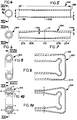
- FIG. 4 through 13 the various steps employed in forming the seat back frame 73 are illustrated.
- the complex shape of frame 73 could be drawn in a variable geometry extrusion die or possibly cast to net shape
- the preferred approach is to start with a conventionally extruded metal tube as illustrated in Figures 4 and 5 having a substantially constant nominal diameter (d) and gauge or wall thickness (t).
- the extrusion is trimmed to a predetermined length (1) to form a tube blank 194 having open ends 196 and 198 and a middle portion, designated 200, intermediate said ends.
- the next step in the method is to re-extrude or mechanically work tube 194 such as by "double butting", hydraulic reduction or other suitable mechanical process which results in varying the wall thickness (t) to establish a thickness profile along length (1) of tube 194.
- the wall thickness profile has a five distinct regions. In two end regions 202 and 204, wall thickness assumes a maximum value (t max ) which is constant throughout the region
- t max maximum value
- a middle region 210 generally centered in tube 194 in the middle portion 200 thereof has a wall thickness that assumes a minium value (t min ) which is constant throughout.
- Intermediate end regions 202 and 204 and middle region 210 are two transition regions 206 and 208 in which the characteristic wall thickness (t) tapers from t max to t min .
- tube 194 is symmetrical about its centerline (c1), it is contemplated that in seat frames only employing a single recliner mechanism, an end region and transition region as described hereinabove maybe formed only on one end of tube 194 and the other tube end remains at a t min dimension.
- the next step in the method is that of forming two substantially right angle corners 212,214 within the middle region 210 of blank 194, whereby the blank assumes a generally inverted U-shape.
- the bending is preferably accomplished by press or punch bending processes wll known in the art.
- the next step in the method involves the forming of blank end regions 202 and 204 into flat sided ellipsoid sections having maximum dimension axes (a-a) which are substantially parallel to one other.
- flat sided it is meant that a substantial portion of the longitudinally extending sides (s) are sufficiently planar to ensure stabilizing surface contact with pivot supports (through intermediate link control bracket).
- a last step involves forming registering pivot pin 50 receiving bores 118 and 120 as well as guide pin 162 receiving bores 122 and 124 as described with reference to the foregoing description with respect to drawing Figures 1 and 3. Bores 118 through 124 are formed in end regions 202 and 204. This step also includes the attachment of reinforcement number 80 to facing mounting locations 216 and 218 within end regions 202 and 204. Mounting locations 216 and 218 straddle a characteristic zero load line (z11). Attachment of reinforcement member 80 is accomplished by welding as close as possible to the zero load line or the use of other suitable fasteners. At this time, additional contours are formed in blank 194 to produce seat back frame 73 as described hereinabove. Such deformation includes forming of flattened portion 82, slots 104 and 106, guide holes 91, 93, 95 and 97 as well as the contours of end surfaces 112 as best viewed in Figure 3.
- Reinforcement member 80 is preferably formed of constant gauge high strength aluminium alloy material which is mechanically worked into its illustrated configuration and has a gauge approximately equal to the maximum thickness t max of the end regions 202 and 204 of blank 194.
- tube 194 can first be annealed, preferably to an "O" or "W" temper prior to working.
- age and work hardening of aluminium is also well-known.
- Shpaing of the blank using a mandrel or other similar tube forming techniques is also contemplated.
- the specifics of such known methodologies is deleted here inasmuch as they are adequately described in numerous treatises.
Landscapes
- Engineering & Computer Science (AREA)
- Mechanical Engineering (AREA)
- Aviation & Aerospace Engineering (AREA)
- Transportation (AREA)
- Seats For Vehicles (AREA)
- Chairs For Special Purposes, Such As Reclining Chairs (AREA)
Abstract
Description
- Fig. 1
- is a front cross-section view taken on the lines IX-IX of Figure 2;
- Fig. 2
- is a top plan view of the seat back frame of the present invention;
- Fig. 3
- is a side, broken cross-section view taken on lines X-X of Figure 1;
- Fig. 4-13
- illustrate various steps in forming the seat back frame.
Claims (35)
- A method for forming a seat back frame (34) for mounting to a seat cushion frame (32) of a motor vehicle seat assembly (10) including the steps of providing a tube (194) having open ends (196,198) and an initially substantially constant diameter and wall thickness therealong, the method characterized in the further steps of:working said wall thickness mechanically to a variable thickness to taper from a maximum wall thickness (202,204) adjacent each end (196,198) to a lesser wall thickness (210) intermediate said ends (196,198); andbending said tube (194) in at least two locations (212,214) of lesser wall thickness (210) to form a substantially U-shaped seat back frame (73) configuration; andforming each of said tube ends (196,198) into flat-sided ellipsoid sections, said flat-sided ellipsoid sections having maximum dimension axes substantially parallel to one another.
- The method of claim 1, further characterized in the step of:forming registering pivot apertures (118,120) adjacent each end (196,198) of said tube (194).
- The method of claim 1, further characterized in the step of:attaching a reinforcement member (80) to said tube (194) to interconnect mounting locations (216,218) near said tube ends (196,198), each location (216,218) disposed substantially on a characteristic zero load line thereof.
- The method of claim 3, further characterized in the step of:attaching a shoulder restraint anchor member (24) to said reinforcement member (80) through an intermediate, vertically elongate tensile loading member (84).
- The method of claim 1, wherein said step of working said tube (194) mechanically effects a wall thickness profile characterized in at least one end region (196,198) of substantially constant, maximum dimension (202,204), a middle region (200) of substantially constant, minimum dimension (210) axially spaced from said end region (202,204), and a transition region (206,208) of substantially constantly varying dimension intermediate said end and middle regions (202,204,210).
- The method of claim 5, wherein said profile is characterized in having an end region (202,204) at each end (196,198) of said tube (194), a single middle region (210) disposed intermediate said end regions (202,204) and a transition region (206,208) disposed intermediate each said end region (202,204) and said middle region (210).
- The method of claim 1, wherein said tube (194) is characterized as having a substantially constant outside diameter after said mechanical working step.
- The method of claim 1, further characterized in the step of:subsequently deforming said tube (194) to establish predetermined contour characteristics.
- The method of claim 1, wherein said tube (194) is characterized in a monolithic, high strength aluminum alloy.
- The method of claim 1 further characterized in the step of:forming said seat back frame (73) from a metal tube (194) having open ends (196,198) and a substantially constant diameter and wall thickness therealong.
- The method of claim 10, further characterized in the step of:forming means for attaching said deformed ends to a vehicle seat cushion frame (32).
- The method of claim 10 further characterized in the steps of:extruding said metal tube (194) having a substantially constant diameter and wall thickness therealong; andtrimming said tube (194) to a predetermined length.
- The method of claim 1 further characterized in the steps of:terminating tubular inboard and outboard vertical leg members (74,76) in open end portions (196,198) adapted to interconnect with said seat cushion frame (32);integrally interconnecting upper portions of said leg members (74,76) with a tubular horizontal base member (200) in a generally inverted U-shape configuration;extending said leg members (74,76) downwardly from said base member (200);minimizing a wall thickness (210) of said base member (200) and upper portions of said leg members (74,76); andmaximizing a wall thickness (202,204) of lower portions (202,204) of said leg members (74,76) which taper upwardly therealong to said minimum wall thickness (210).
- The method of claim 1 further characterized in the steps of:supporting a seat cushion (21) with a lower frame portion (36);supporting a seat back (22)with an upper frame portion (34);forming said upper portion (34) into a generally inverted U-shaped member (73) from a single piece of lightweight, high strength metallic tubing (194) having a base (200) and two substantially parallel legs (74,76) extending from said base (200);pivotally mounting said two parallel legs (74,76) of said upper portion (34) to said lower frame portion (36) adjacent free open ends (196,198) thereof; andtapering a wall thickness of said tubing (194) from a maximum dimension (202,204) adjacent said open ends (196,198) to a minimum dimension (210) adjacent said base (200).
- A seat back frame (34) adapted for mounting to a seat cushion frame (36) for a motor vehicle seat assembly (32), said seat back frame (34) including a tube (194) having open ends (196,198) and an initially substantially constant diameter and wall thickness therealong, the tube characterized in that:said wall thickness is mechanically worked to a variable thickness to taper from a maximum dimension (202,204) adjacent said ends (196,198) to a lesser dimension (210) intermediate said ends (196,198), said tube (194) bent in at least two locations (212,214) of lesser wall thickness (210) to form a substantially U-shaped frame (73) configuration; andsaid tube ends (196,198) is formed into flat-sided ellipsoid sections having maximum dimension axes which are substantially parallel.
- The seat back frame (34) of claim 15 further characterized in that:said tube (194) is formed of metal as one-piece.
- The seat back frame (34) of claim 15 further characterized in that:said tube (194) is formed of extruded metal and trimmed to a predetermined length, said trimmed tube (194) is bent in two locations (212,214) of minimum wall thickness to form two substantially right angle corners whereby said tube (194) assumes a general U-shape and said tube ends (196,198) are deformed into flat-sided ellipsoid sections having maximum dimension axes substantially parallel to one another.
- The seat back frame (34) of claim 15 further characterized in that:said tube includes tubular inboard and outboard vertical leg members (74,76) and a tubular horizontal base portion (200) integrally interconnecting upper portions of said leg members (74,76) in a generally inverted U-shape configuration, said leg members (74,76) extending downwardly from said base portion (200) and terminating in open end portions (196,198) adapted for interconnection with said seat cushion frame (36), said base portion (200) and upper portions of said leg members (74,76) having a characteristic minimum wall thickness (210) and lower portions (196,198) of said leg members (74,76) having a characteristic maximum wall thickness (202,204) which tapers upwardly therealong to said minimum wall thickness (210).
- The seat back frame (34) of claim 18, further characterized in that:said lower portions (196,198) each define a region (202,204) of substantially constant maximum wall thickness.
- The seat back frame (34) of claim 19, further characterized in that:said upper portions are characterized by substantially circular cross-sections and said lower portions (196,198) are characterized by flat-sided ellipsoid cross-sections having substantially parallel maximum dimension axes.
- The seat back frame (34) of claim 20, further characterized in that:said lower portions define registering pivot apertures (118,120).
- The seat back frame (34) of claim 18, further characterized in that:a generally horizontally extending tubular reinforcement member (80) interconnects mounting locations (216,218) defined on said lower portions (196,198).
- The seat back frame (34) of claim 22, further characterized in that:said mounting locations (216,218) longitudinally traverse a characteristic zero load line of each said leg member (74,76).
- The seat back frame (34) of claim 22, further characterized in that:a shoulder restraint anchor member (24) is disposed nearly spaced from said upper portion of one of said leg members (74,76) and interconnected to said reinforcing member (80) through an intermediate, vertically elongate tensile loading member (84).
- The seat back frame (34) of claim 24, furhter characterized in that:said loading member (84) is longitudinally resilient and laterally rigid.
- The seat back frame (34) of claim 18, further characterized in that:said base member (200) defines a generally planar seat headrest mounting surface (82).
- The seat back frame (34) of claim 18, further characterized in that:said vertical leg members (74,76) and base portion (200) are integrally formed from a single piece of tubular metallic material (194).
- The seat back frame (34) of claim 27, further characterized in that:said single piece of tubular metallic material (194) has a substantially constant outside diameter therealong.
- The seat back frame (34) of claim 27, further characterized in that:said single piece of tubular metallic material (194) is a monolithic, high strength aluminum alloy.
- The seat back frame (34) of claim 18, further characterized in that:said seat back frame (73) has a generally A-frame profile.
- The seat back frame (34) of claim 15 for assembly in a seat frame (32) including a lower frame portion (36) supporting a seat cushion (21), an upper frame portion (34) supporting a seat back (22), said upper portion (34) including a generally inverted U-shaped member (73) formed from a tube (194) having a base (200) and two substantially parallel legs (74,76) extending from said base (200) and pivotally mounted to said lower frame portion (36) adjacent free open ends (196,198) thereof, said tube (194) further characterized in that:said tube (194) is formed of single piece of lightweight, high strength metallic and has a characteristic wall thickness which tapers from a maximum dimension (202,204) adjacent said open ends (196,198) to a minimum dimension (210) adjacent said base (200).
- The seat frame (32) of claim 31 further characterized in that:adjuster means (40) operates to establish a fixed angular position between said upper and lower frame portions (34,36).
- The seat frame (32) of claim 32, further characterized in that:said adjuster means (40) includes an actuator (62) carried by said lower frame portion (36) and a linkage system (130,154,164) pivotally interconnecting said actuator (62) and upper frame portion (34).
- The seat frame (32) of claim 33, further characterized in that:said linkage system (130,154,164) includes means (154) operative to selectively disengage said adjuster means (40) from said upper frame portion (34).
- The seat frame (32) of claim 33, further characterized in that:at least a portion of said linkage system (130,154,164) is disposed within the open ends (196,198) of said legs (74,76).
Applications Claiming Priority (3)
| Application Number | Priority Date | Filing Date | Title |
|---|---|---|---|
| US07/840,774 US5338100A (en) | 1992-02-24 | 1992-02-24 | High strength automotive seat frame and method |
| US840774 | 1992-02-24 | ||
| PCT/US1993/001647 WO1993016896A1 (en) | 1992-02-24 | 1993-02-23 | High strength automotive seat frame and method |
Publications (2)
| Publication Number | Publication Date |
|---|---|
| EP0627997A1 EP0627997A1 (en) | 1994-12-14 |
| EP0627997B1 true EP0627997B1 (en) | 1998-08-19 |
Family
ID=25283195
Family Applications (1)
| Application Number | Title | Priority Date | Filing Date |
|---|---|---|---|
| EP93906201A Expired - Lifetime EP0627997B1 (en) | 1992-02-24 | 1993-02-23 | High strength automotive seat frame and method |
Country Status (7)
| Country | Link |
|---|---|
| US (2) | US5338100A (en) |
| EP (1) | EP0627997B1 (en) |
| JP (1) | JP2718828B2 (en) |
| CA (1) | CA2126758C (en) |
| DE (1) | DE69320459T2 (en) |
| MX (1) | MX9207499A (en) |
| WO (1) | WO1993016896A1 (en) |
Families Citing this family (21)
| Publication number | Priority date | Publication date | Assignee | Title |
|---|---|---|---|---|
| NO173538C (en) * | 1991-09-06 | 1993-12-29 | Norsk Hydro As | Construction beam and method of production of the same |
| DE4315521C1 (en) * | 1993-05-10 | 1994-05-11 | Austria Metall | Prodn. of frame for vehicle seat - using aluminium@ profiles with ramp-type plate at front frame part forming front seat part and running inclined from back to front |
| US5499863A (en) * | 1993-05-17 | 1996-03-19 | Toyota Shatai Kabushiki Kaisha | Seat back frame |
| US5720511A (en) * | 1993-08-11 | 1998-02-24 | Alumax Extrusions, Inc. | Frame apparatus and process for the manufacture of same |
| FR2720141B1 (en) * | 1994-05-20 | 1996-08-02 | Cesa | Improved element of seat frame, part making use of it and its application in particular to a vehicle seat. |
| US5988741A (en) * | 1995-04-17 | 1999-11-23 | Voss; Darrell W. | Bicycle seat post flare post |
| AT407502B (en) * | 1995-05-10 | 2001-04-25 | Euromotive Gmbh | METHOD FOR PRODUCING A U-SHAPED FRAME OF A REAR OF A MOTOR VEHICLE SEAT, THAT IS COMPOSED OF TWO LONGITUDE AND A CROSS-BAR |
| US5575564A (en) * | 1995-05-26 | 1996-11-19 | Itt Automotive, Inc. | Seat track apparatus |
| FR2736011B1 (en) * | 1995-06-30 | 1997-09-26 | Cesa | METAL TUBE ELEMENT, FRAME FOR MOTOR VEHICLE SEAT PROVIDED WITH THIS ELEMENT, AND SEAT BACKREST PROVIDED WITH THIS FRAME |
| US5895090A (en) * | 1996-09-24 | 1999-04-20 | Lear Corporation | Vehicle with integrated restraint system |
| US5749135A (en) * | 1997-03-19 | 1998-05-12 | General Motors Corporation | Method for extruding integral seat back frame |
| US6293616B1 (en) * | 2000-01-10 | 2001-09-25 | Ford Global Technologies, Inc. | Modular rail for roof and windshield |
| US6789846B2 (en) * | 2002-12-20 | 2004-09-14 | Lear Corporation | Vehicle seat having a movable head restraint |
| JP5339774B2 (en) * | 2008-05-20 | 2013-11-13 | 日本発條株式会社 | Frame structure of vehicle seat back and vehicle seat back having the structure |
| DE102009017374A1 (en) * | 2009-04-14 | 2010-10-21 | GM Global Technology Operations, Inc., Detroit | Method for producing a structural component for a motor vehicle |
| DE102012003367A1 (en) * | 2012-02-22 | 2013-08-22 | Grammer Ag | headrest |
| WO2014115106A1 (en) * | 2013-01-23 | 2014-07-31 | Zodiac Seats France | Compact seat kinematic |
| US20150182027A1 (en) * | 2013-12-27 | 2015-07-02 | Hong-Yuan Chang | Composite chair |
| US9308842B2 (en) * | 2014-02-24 | 2016-04-12 | Ford Global Technologies, Llc | Pyrotechnic fastener seat arrangement for unbelted occupant protection |
| KR101677464B1 (en) * | 2015-09-25 | 2016-11-18 | 주식회사 서연이화 | Vehicle Seat Equipped with Mesh-type String Elements |
| IT201700043293A1 (en) * | 2017-04-20 | 2018-10-20 | F I S A Srl | STRUCTURE OF PASSENGER SEATS FOR VEHICLES |
Family Cites Families (37)
| Publication number | Priority date | Publication date | Assignee | Title |
|---|---|---|---|---|
| US1684062A (en) * | 1924-12-22 | 1928-09-11 | Ashtabula Bow Socket Company | Back for automobile seats and the like |
| US2720914A (en) * | 1952-12-08 | 1955-10-18 | Briggs Mfg Co | Seat structure for vehicles |
| US2783826A (en) * | 1954-07-06 | 1957-03-05 | Haltenberger Jules | Automobile front seat backrest control |
| US2924265A (en) * | 1955-04-14 | 1960-02-09 | Gen Motors Corp | Vehicle seat |
| DE1024816B (en) * | 1955-05-31 | 1958-02-20 | Nsu Werke Ag | Seat for motor vehicles with a frame made of pipes or the like |
| US2915111A (en) * | 1957-08-26 | 1959-12-01 | American Metal Prod | Adjustable seat back |
| US3259435A (en) * | 1964-02-10 | 1966-07-05 | United States Steel Corp | Spring module |
| US3398987A (en) * | 1966-12-01 | 1968-08-27 | Young Spring & Wire Corp | Folding automobile seat |
| US3471197A (en) * | 1967-03-20 | 1969-10-07 | Richard N Ely | Passenger restraining system |
| US3433524A (en) * | 1967-05-02 | 1969-03-18 | Ford Motor Co | Seat back latch mechanism |
| FR1569823A (en) * | 1968-04-04 | 1969-06-06 | ||
| GB1233054A (en) * | 1968-06-13 | 1971-05-26 | ||
| US3638999A (en) * | 1969-12-17 | 1972-02-01 | Young Spring & Wire Corp | Vehicle seat construction |
| DE2031382A1 (en) * | 1970-06-25 | 1971-12-30 | Volkswagenwerk Ag, 3180 Wolfsburg | Adjusting device for a seat arrangement, in particular for motor vehicles |
| US4015812A (en) * | 1975-10-28 | 1977-04-05 | International Telephone And Telegraph Corporation | Seat adjustment mechanism |
| DE2602022A1 (en) * | 1976-01-21 | 1977-07-28 | Bernd Seifert | Safety belt integrated with car seat - has shoulder strap fixed rigidly to rear of back rest and belly band lead through opening under seat |
| US4432583A (en) * | 1981-04-01 | 1984-02-21 | International Telephone And Telegraph Corporation | Vehicle seat track apparatus |
| FR2515946B1 (en) * | 1981-11-11 | 1985-10-11 | Keiper Automobiltechnik Gmbh | BACKREST FRAME FOR SEATS, ESPECIALLY FOR MOTOR VEHICLE SEATS |
| US4492408A (en) * | 1982-01-19 | 1985-01-08 | Allen Industries, Inc. | Vehicle seat construction and method of making the same |
| US4625537A (en) * | 1982-12-06 | 1986-12-02 | Grumman Aerospace Corporation | Localized boss thickening by cold swaging |
| US4875735A (en) * | 1984-03-30 | 1989-10-24 | Moyer George A | Seatback recliner mechanism |
| IT1179651B (en) * | 1984-05-09 | 1987-09-16 | Comind Spa | SEAT BACKREST FOR MOTOR VEHICLES AND PROCEDURE FOR ITS MANUFACTURE |
| US4822100A (en) * | 1984-07-19 | 1989-04-18 | Fisher Dynamics Corporation | Quick release mechanism for gear operated seat recliner |
| US5028091A (en) * | 1985-10-21 | 1991-07-02 | Keiper Recaro, Inc. | Remote seat back adjuster |
| FR2593440B1 (en) * | 1986-01-27 | 1988-05-06 | Peugeot Cycles | MOTOR VEHICLE SEAT FRAME OR THE LIKE |
| FR2611827B1 (en) * | 1987-03-04 | 1989-07-28 | Cousin Cie Ets A & M Freres | CONFORMED SEAT REINFORCEMENT TUBE JOINT PART WITH A BACKREST ADJUSTMENT MECHANISM |
| JPH0640519Y2 (en) * | 1987-07-31 | 1994-10-26 | 池田物産株式会社 | Reclining device |
| US4832409A (en) * | 1987-09-08 | 1989-05-23 | General Motors Corporation | Restraint belt load capacity fore and aft power seat adjuster apparatus |
| US4943116A (en) * | 1987-12-29 | 1990-07-24 | Akira Ohwada | Reclining angle adjustment device |
| US4986514A (en) * | 1988-10-31 | 1991-01-22 | Fujikiko Kabushiki Kaisha | Seat reclining device |
| JPH0628035Y2 (en) * | 1989-02-25 | 1994-08-03 | 池田物産株式会社 | Reclining adjuster cover device |
| US4929024A (en) * | 1989-06-29 | 1990-05-29 | Fisher Dynamics Corporation | Power seat recliner |
| US4962963A (en) * | 1989-07-24 | 1990-10-16 | Fisher Dynamics Corporation | Power linear seat recliner |
| GB2235620B (en) * | 1989-09-06 | 1992-09-23 | Ihw Eng Ltd | Reclining seat frame |
| US4969682A (en) * | 1989-10-02 | 1990-11-13 | General Motors Corporation | Seat assembly with roller seat back hinge |
| US5052752A (en) * | 1990-06-21 | 1991-10-01 | Fisher Dynamics Corporation | Infinitely adjustable linear seat recliner |
| JPH0753556Y2 (en) * | 1990-11-26 | 1995-12-13 | 池田物産株式会社 | Back frame |
-
1992
- 1992-02-24 US US07/840,774 patent/US5338100A/en not_active Expired - Fee Related
- 1992-12-22 MX MX9207499A patent/MX9207499A/en not_active IP Right Cessation
-
1993
- 1993-02-23 EP EP93906201A patent/EP0627997B1/en not_active Expired - Lifetime
- 1993-02-23 JP JP5515055A patent/JP2718828B2/en not_active Expired - Lifetime
- 1993-02-23 DE DE69320459T patent/DE69320459T2/en not_active Expired - Fee Related
- 1993-02-23 WO PCT/US1993/001647 patent/WO1993016896A1/en not_active Ceased
- 1993-02-23 CA CA002126758A patent/CA2126758C/en not_active Expired - Fee Related
- 1993-12-03 US US08/162,345 patent/US5528829A/en not_active Expired - Fee Related
Also Published As
| Publication number | Publication date |
|---|---|
| MX9207499A (en) | 1993-09-01 |
| CA2126758C (en) | 1996-05-28 |
| CA2126758A1 (en) | 1993-09-02 |
| DE69320459D1 (en) | 1998-09-24 |
| US5338100A (en) | 1994-08-16 |
| DE69320459T2 (en) | 1999-05-06 |
| US5528829A (en) | 1996-06-25 |
| EP0627997A1 (en) | 1994-12-14 |
| JP2718828B2 (en) | 1998-02-25 |
| WO1993016896A1 (en) | 1993-09-02 |
| JPH07503212A (en) | 1995-04-06 |
Similar Documents
| Publication | Publication Date | Title |
|---|---|---|
| US5306073A (en) | High strength motor vehicle seat recliner | |
| US5528829A (en) | Method of making a high strength automotive seat frame | |
| US6296300B1 (en) | Vehicle body structure | |
| US5447360A (en) | Side impact seat back structure | |
| US5564785A (en) | Seat frame assembly for a motor vehicle | |
| US6334643B1 (en) | Vehicle seat | |
| US6447052B2 (en) | Body structure for vehicle | |
| US6554356B1 (en) | Shock absorbing vehicle seat frame | |
| JP5550367B2 (en) | Vehicle roof column assembly | |
| JP7320949B2 (en) | vehicle seat | |
| EP0590237A1 (en) | Automotive seat having integrally mounted seat belt assembly | |
| JP6662184B2 (en) | Vehicle seat | |
| AU753427B2 (en) | A retractable automotive seat assembly | |
| US5288134A (en) | Seat assembly with integrated seat cushion and seat track frame | |
| US5570508A (en) | Method of making a high strength automotive seat frame | |
| EP1428707B1 (en) | Vehicle door assembly | |
| JPH06506418A (en) | Passenger car body support structure | |
| US6019412A (en) | Seat assembly | |
| JPH036013B2 (en) | ||
| JPH1044843A (en) | Energy absorption of rear-seat-back hinge bracket | |
| JP3146544B2 (en) | Cab-over type car seat structure | |
| JP2000103274A (en) | Car seat | |
| JPH0672392A (en) | Seat leg structure to absorb impact energy | |
| KR20050047681A (en) | Structure for mounting of seatback in rearseat for automobile |
Legal Events
| Date | Code | Title | Description |
|---|---|---|---|
| PUAI | Public reference made under article 153(3) epc to a published international application that has entered the european phase |
Free format text: ORIGINAL CODE: 0009012 |
|
| 17P | Request for examination filed |
Effective date: 19940629 |
|
| AK | Designated contracting states |
Kind code of ref document: A1 Designated state(s): DE FR GB IT |
|
| 17Q | First examination report despatched |
Effective date: 19960710 |
|
| GRAG | Despatch of communication of intention to grant |
Free format text: ORIGINAL CODE: EPIDOS AGRA |
|
| RAP1 | Party data changed (applicant data changed or rights of an application transferred) |
Owner name: LEAR CORPORATION |
|
| GRAG | Despatch of communication of intention to grant |
Free format text: ORIGINAL CODE: EPIDOS AGRA |
|
| GRAG | Despatch of communication of intention to grant |
Free format text: ORIGINAL CODE: EPIDOS AGRA |
|
| GRAH | Despatch of communication of intention to grant a patent |
Free format text: ORIGINAL CODE: EPIDOS IGRA |
|
| GRAH | Despatch of communication of intention to grant a patent |
Free format text: ORIGINAL CODE: EPIDOS IGRA |
|
| GRAA | (expected) grant |
Free format text: ORIGINAL CODE: 0009210 |
|
| AK | Designated contracting states |
Kind code of ref document: B1 Designated state(s): DE FR GB IT |
|
| REF | Corresponds to: |
Ref document number: 69320459 Country of ref document: DE Date of ref document: 19980924 |
|
| ET | Fr: translation filed | ||
| PGFP | Annual fee paid to national office [announced via postgrant information from national office to epo] |
Ref country code: GB Payment date: 19990203 Year of fee payment: 7 Ref country code: FR Payment date: 19990203 Year of fee payment: 7 |
|
| PGFP | Annual fee paid to national office [announced via postgrant information from national office to epo] |
Ref country code: DE Payment date: 19990204 Year of fee payment: 7 |
|
| PLBE | No opposition filed within time limit |
Free format text: ORIGINAL CODE: 0009261 |
|
| STAA | Information on the status of an ep patent application or granted ep patent |
Free format text: STATUS: NO OPPOSITION FILED WITHIN TIME LIMIT |
|
| 26N | No opposition filed | ||
| PG25 | Lapsed in a contracting state [announced via postgrant information from national office to epo] |
Ref country code: GB Free format text: LAPSE BECAUSE OF NON-PAYMENT OF DUE FEES Effective date: 20000223 |
|
| GBPC | Gb: european patent ceased through non-payment of renewal fee |
Effective date: 20000223 |
|
| PG25 | Lapsed in a contracting state [announced via postgrant information from national office to epo] |
Ref country code: FR Free format text: LAPSE BECAUSE OF NON-PAYMENT OF DUE FEES Effective date: 20001031 |
|
| PG25 | Lapsed in a contracting state [announced via postgrant information from national office to epo] |
Ref country code: DE Free format text: LAPSE BECAUSE OF NON-PAYMENT OF DUE FEES Effective date: 20001201 |
|
| REG | Reference to a national code |
Ref country code: FR Ref legal event code: ST |
|
| PG25 | Lapsed in a contracting state [announced via postgrant information from national office to epo] |
Ref country code: IT Free format text: LAPSE BECAUSE OF NON-PAYMENT OF DUE FEES;WARNING: LAPSES OF ITALIAN PATENTS WITH EFFECTIVE DATE BEFORE 2007 MAY HAVE OCCURRED AT ANY TIME BEFORE 2007. THE CORRECT EFFECTIVE DATE MAY BE DIFFERENT FROM THE ONE RECORDED. Effective date: 20050223 |