EP0626836B1 - Variable angle screw for spinal implant system - Google Patents
Variable angle screw for spinal implant system Download PDFInfo
- Publication number
- EP0626836B1 EP0626836B1 EP93904847A EP93904847A EP0626836B1 EP 0626836 B1 EP0626836 B1 EP 0626836B1 EP 93904847 A EP93904847 A EP 93904847A EP 93904847 A EP93904847 A EP 93904847A EP 0626836 B1 EP0626836 B1 EP 0626836B1
- Authority
- EP
- European Patent Office
- Prior art keywords
- bone screw
- eyebolt
- variable angle
- head
- washer
- Prior art date
- Legal status (The legal status is an assumption and is not a legal conclusion. Google has not performed a legal analysis and makes no representation as to the accuracy of the status listed.)
- Expired - Lifetime
Links
Images

Classifications
-
- A—HUMAN NECESSITIES
- A61—MEDICAL OR VETERINARY SCIENCE; HYGIENE
- A61B—DIAGNOSIS; SURGERY; IDENTIFICATION
- A61B17/00—Surgical instruments, devices or methods, e.g. tourniquets
- A61B17/56—Surgical instruments or methods for treatment of bones or joints; Devices specially adapted therefor
- A61B17/58—Surgical instruments or methods for treatment of bones or joints; Devices specially adapted therefor for osteosynthesis, e.g. bone plates, screws, setting implements or the like
- A61B17/68—Internal fixation devices, including fasteners and spinal fixators, even if a part thereof projects from the skin
- A61B17/70—Spinal positioners or stabilisers ; Bone stabilisers comprising fluid filler in an implant
- A61B17/7001—Screws or hooks combined with longitudinal elements which do not contact vertebrae
- A61B17/7035—Screws or hooks, wherein a rod-clamping part and a bone-anchoring part can pivot relative to each other
- A61B17/7038—Screws or hooks, wherein a rod-clamping part and a bone-anchoring part can pivot relative to each other to a different extent in different directions, e.g. within one plane only
-
- A—HUMAN NECESSITIES
- A61—MEDICAL OR VETERINARY SCIENCE; HYGIENE
- A61B—DIAGNOSIS; SURGERY; IDENTIFICATION
- A61B17/00—Surgical instruments, devices or methods, e.g. tourniquets
- A61B17/56—Surgical instruments or methods for treatment of bones or joints; Devices specially adapted therefor
- A61B17/58—Surgical instruments or methods for treatment of bones or joints; Devices specially adapted therefor for osteosynthesis, e.g. bone plates, screws, setting implements or the like
- A61B17/68—Internal fixation devices, including fasteners and spinal fixators, even if a part thereof projects from the skin
- A61B17/70—Spinal positioners or stabilisers ; Bone stabilisers comprising fluid filler in an implant
- A61B17/7049—Connectors, not bearing on the vertebrae, for linking longitudinal elements together
-
- A—HUMAN NECESSITIES
- A61—MEDICAL OR VETERINARY SCIENCE; HYGIENE
- A61B—DIAGNOSIS; SURGERY; IDENTIFICATION
- A61B17/00—Surgical instruments, devices or methods, e.g. tourniquets
- A61B17/56—Surgical instruments or methods for treatment of bones or joints; Devices specially adapted therefor
- A61B17/58—Surgical instruments or methods for treatment of bones or joints; Devices specially adapted therefor for osteosynthesis, e.g. bone plates, screws, setting implements or the like
- A61B17/68—Internal fixation devices, including fasteners and spinal fixators, even if a part thereof projects from the skin
- A61B17/70—Spinal positioners or stabilisers ; Bone stabilisers comprising fluid filler in an implant
- A61B17/7001—Screws or hooks combined with longitudinal elements which do not contact vertebrae
- A61B17/7002—Longitudinal elements, e.g. rods
- A61B17/7011—Longitudinal element being non-straight, e.g. curved, angled or branched
-
- A—HUMAN NECESSITIES
- A61—MEDICAL OR VETERINARY SCIENCE; HYGIENE
- A61B—DIAGNOSIS; SURGERY; IDENTIFICATION
- A61B17/00—Surgical instruments, devices or methods, e.g. tourniquets
- A61B17/56—Surgical instruments or methods for treatment of bones or joints; Devices specially adapted therefor
- A61B17/58—Surgical instruments or methods for treatment of bones or joints; Devices specially adapted therefor for osteosynthesis, e.g. bone plates, screws, setting implements or the like
- A61B17/68—Internal fixation devices, including fasteners and spinal fixators, even if a part thereof projects from the skin
- A61B17/70—Spinal positioners or stabilisers ; Bone stabilisers comprising fluid filler in an implant
- A61B17/7001—Screws or hooks combined with longitudinal elements which do not contact vertebrae
- A61B17/7041—Screws or hooks combined with longitudinal elements which do not contact vertebrae with single longitudinal rod offset laterally from single row of screws or hooks
-
- A—HUMAN NECESSITIES
- A61—MEDICAL OR VETERINARY SCIENCE; HYGIENE
- A61B—DIAGNOSIS; SURGERY; IDENTIFICATION
- A61B17/00—Surgical instruments, devices or methods, e.g. tourniquets
- A61B17/56—Surgical instruments or methods for treatment of bones or joints; Devices specially adapted therefor
- A61B17/58—Surgical instruments or methods for treatment of bones or joints; Devices specially adapted therefor for osteosynthesis, e.g. bone plates, screws, setting implements or the like
- A61B17/68—Internal fixation devices, including fasteners and spinal fixators, even if a part thereof projects from the skin
- A61B17/70—Spinal positioners or stabilisers ; Bone stabilisers comprising fluid filler in an implant
- A61B17/7049—Connectors, not bearing on the vertebrae, for linking longitudinal elements together
- A61B17/7052—Connectors, not bearing on the vertebrae, for linking longitudinal elements together of variable angle or length
-
- A—HUMAN NECESSITIES
- A61—MEDICAL OR VETERINARY SCIENCE; HYGIENE
- A61B—DIAGNOSIS; SURGERY; IDENTIFICATION
- A61B17/00—Surgical instruments, devices or methods, e.g. tourniquets
- A61B17/56—Surgical instruments or methods for treatment of bones or joints; Devices specially adapted therefor
- A61B17/58—Surgical instruments or methods for treatment of bones or joints; Devices specially adapted therefor for osteosynthesis, e.g. bone plates, screws, setting implements or the like
- A61B17/68—Internal fixation devices, including fasteners and spinal fixators, even if a part thereof projects from the skin
- A61B17/70—Spinal positioners or stabilisers ; Bone stabilisers comprising fluid filler in an implant
- A61B17/7055—Spinal positioners or stabilisers ; Bone stabilisers comprising fluid filler in an implant connected to sacrum, pelvis or skull
-
- A—HUMAN NECESSITIES
- A61—MEDICAL OR VETERINARY SCIENCE; HYGIENE
- A61B—DIAGNOSIS; SURGERY; IDENTIFICATION
- A61B17/00—Surgical instruments, devices or methods, e.g. tourniquets
- A61B17/56—Surgical instruments or methods for treatment of bones or joints; Devices specially adapted therefor
- A61B17/58—Surgical instruments or methods for treatment of bones or joints; Devices specially adapted therefor for osteosynthesis, e.g. bone plates, screws, setting implements or the like
- A61B17/68—Internal fixation devices, including fasteners and spinal fixators, even if a part thereof projects from the skin
- A61B17/84—Fasteners therefor or fasteners being internal fixation devices
- A61B17/86—Pins or screws or threaded wires; nuts therefor
Definitions
- the present invention relates generally to the field of spinal implant systems of the type which employ spinal rods connected at various locations along the spinal column by various fixation elements including spinal screws and, more particularly, to a spinal screw fixation element which provides variable angle adjustability.
- a bendable rod is longitudinally disposed adjacent the vertebral column and is fixed to various vertebrae along the length of the column by way of a number of fixation elements.
- fixation elements can be provided, such as hooks or bone screws, which are configured to engage specific portions of the vertebra.
- TSRHTM spinal system of Danek Medical, Inc An example of one such system is the TSRHTM spinal system of Danek Medical, Inc.
- the hooks or screws are engaged to the spinal rod by way of eyebolts.
- the eyebolts are received over the spinal rod and captured within a yoke means formed on the head of the fixation hook or screw.
- a nut is threaded onto a threaded post of the eyebolt to clamp the yoke and to provide a three-point shear clamp force positively locking the hook or screw element to the spinal fixation rod. Details of the TSRH spinal implant system are disclosed in the "Surgical Technique Manual" provided by Danek Medical, Inc., published in 1990.
- U. S. Patent No. 4,946,458 to Harms et al. discloses a pedicle screw provided with a ball and socket type arrangement for permitting angulation of the bone screw relative to the receiver.
- U. S. Patent No. 4,987,892 to Krag et al. discloses a spinal fixation system employing pedicle screws having radially splined heads interdigitating with radial splines or teeth integrally formed upon articulating clamps which in turn clamp about a stabilizing rod.
- the articulating clamp arrangement requires the radial splines be offset relative to the stabilizing rod. This offset creates alignment problems which make it difficult, if not impossible, to permit the screws to be angularly rotated in a plane perpendicular to the axis of the stabilizing rod.
- the Krag et al. system requires a specially formed articulating clamp for the pedicle screw.
- German Patent No. 3,219,575 C2 to Kluger discloses a spinal implant system which provides angular adjustment of the bone screws by relative movement of interdigitating disk contact surfaces on corner pieces within which each bone screw is mounted.
- the system is mechanically complex, in that separate adjusting means are needed to angularly adjust the orientation of the bone screws and to fix the position of the bone screws relative to the corner pieces and to one another. Any rotational adjustment of the bone pins in a plane normal to the spinal rods changes the distance between the pins, requiring further adjustment of the sleeve nut. Further, the system is limited to situations where only two pins or other fixation elements are required on the same rod.
- a variable angle bone screw system for use in a spinal implant system to connect a vertebral fixation element to a spinal rod extending adjacent the vertebral column in a patient, comprising:
- An additional object and benefit of the present invention is served by providing an improved spinal implant system which permits three dimensional adjustment of the bone screw fixation elements without undesirably complicating the overall design of the system or rendering installation of the spinal rod more difficult.
- the bone screw has a yoke portion defining an opening to permit top-loading of the eyebolt onto the variable angle screw.
- the open configuration of the screw allows insertion of the screw into the pedicle, for example, and then subsequent engagement to an appropriately contoured spinal rod by way of an eyebolt configured in accordance with the present invention.
- Fig. 1 shows part of the pelvis and spinal column generally designated at 11 receiving a spinal implant system 10.
- the system 10 includes a series of four spinal rods. Two of them, rods 12 and 13, have their lower ends secured in the sacrum while the other two, rods 14 and 16, extend upward along the spinal column.
- a plurality of bone screws and/or hooks are employed at spaced locations along rods 14 and 16 for connection of the rods to the vertebrae, preferably in the pedicle.
- spacer links, screws and/or hooks are connected to the rods 12 and 13. All of the spacers, screws and/or hooks are clamped to the rods by eyebolts.
- the spacer link 17 establishing the space between the rods 12 and 13 at the link location is affixed to the rods 12 and 13 by eyebolts 18 and 19, respectively.
- the rod 14 is connected to the spinal column by fixation elements 15.
- the particular type of spinal fixation element employed may be either a hook type element or a bone screw. If hooks are employed as the fixation elements, the hooks may be constructed in a variety of shapes and sizes such as shown and described in pages 6-10 of the Danek Surgical Technique Manual for the TSRHTM Spinal Implant System, published by Danek Medical, Inc. of Memphis, Tennessee, on February 1, 1990. All screws, hooks and spacers have in common, a "three-point shear" clamp feature when combined with the eyebolt as described in that manual. It should be appreciated, however, that the bone screw of the previous TSRHTM Spinal Implant System, such as described in pages 9-10 of that manual, can not vary its angular orientation relative to the rod axis.
- the screw 20 has a head 21 and threaded shank 22.
- the shank 22 is threaded for engaging the pedicle of a vertebra.
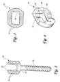
- the head 21 has a U-shape forming an open yoke 23 which receives the threaded stem of an eyebolt.
- the open yoke 23 provides an advantageous top-loading aspect to the screw 20.
- One side of the head 21 is formed to define a series of radially extending teeth or splines 24. In the preferred embodiment each spline 24 circumscribes an arc of six degrees.
- the screws 20 are preferably provided in diameters of 5.5 and 6.5 mm and in lengths ranging from 25 to 50 mm.
- FIGS. 3 and 4 depict the variable angle washer 25.
- One side of the washer 25 defines a series of radially extending teeth or splines 27 which are formed to interdigitate with the splines 24 on a corresponding screw 20.
- the opposed side of washer 25 defines an axially aligned pair of part cylindrical shaped recesses 28 which receive therein the spinal rod when the washer is mounted thereon.
- the through opening 30 in washer 25 is rectangularly shaped and sized to permit washer 25 to be received over the head portion of an eyebolt in a close sliding fit.
- FIG. 5 shows a variable angle screw 20, washer 25 and eyebolt/locknut assembly 26 mounted to a spinal rod 16.
- Eyebolt/locknut assembly 26 includes eyebolt 26a and locknut 26b.
- the eyebolt/locknut assembly is a conventionally known spinal rod fastener and may preferably be a 1/4 inch eyebolt/locknut assembly provided by Danek Medical, Inc. as part number 808-029 for use with the Danek TSRHTM Spinal Implant System.
- Eyebolt 26a is situated at a desired location along rod 16 and washer 25 is mounted onto eyebolt 26a over the threaded stem 31 so that the washer 25 surrounds eyebolt head 32 and abuts rod 16 with the rod 16 received within recesses 28 so as to provide a yoke clamping force which securely fixes the position of eyebolt 26a on rod 16.
- the splines 27 extend from the head 32 a sufficient distance such that with the splines 24 and 27 in interdigitating contact with the head 21 of bone screw 20 can be positioned in any desired angular orientation without interference with head 32.
- the yoked head 21 of bone screw 20 permits top-loading the stem 31 of the eyebolt 26a onto the screw 20 without having to manipulate the screw or spinal rod to pass the stem through a closed of the screw, as in prior devices such as shown in the aforementioned Krag et al. patent No. 4,987,897.
- a locknut 26b is threaded over the threaded stem 31 until it contacts the non-splined side of screw 20. As nut 26b is tightened, it pushes the screw 20 and washer 25 towards the rod 16 so that the rod 16 will be clamped between the eyebolt 26a and washer 25 in the manner of a three-point shear clamp.
- variable angle screws 20 may be mounted to the spinal rod using the same eyebolt fasteners as are used to mount other fixation elements such as hooks and spacers, thus reducing the number of different parts and simplifying the installation procedure.
- variable bone screw of the present invention may be mounted to a lateral offset connector of the type disclosed in U.S. Patent No. 5209752 (application no. 07/803,325) filed December 4, 1991 entitled Lateral Offset Connector for Spinal Implant System.
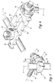
- FIG. 6 shows an offset connector 40 mounted to a spinal rod 16 by an eyebolt/locknut assembly 26.
- the connector 40 includes a pair of arms 45 which serve as a yoke clamping eyebolt 26 and preventing its movement along rod 16.
- the washer 25 and variable angle bone screw 20 are mounted to a guide portion having a rectangular shape for receiving the washer and a threaded post 42 extending therefrom.
- the washer 25 may be dispensed with as a separate element and its radial splines may be integrally incorporated into the connector 40 at the base of threaded post 42.
- a locknut 43 secures the position of the bone screw 20.
- the lateral offset of screw 20 relative to rod 16 may be selectively adjusted by selective positioning of rod 16 in pairs of aligned grooves 44, thereby accommodating abnormal lateral curvatures of the spine in the saggital plane.
- the present invention provides a variable angle screw that can be engaged within the pedicle of a vertebra and then subsequently fastened to a contoured spinal rod without requiring the excessive manipulation characteristic with prior similar devices.
- the spinal screw 20 of the present invention combines a top-loading feature with the capability for interdigitated engagement with the spinal rod to accommodate varying angles of the screw relative to the rod.
- the washer 25 may be trapped on the eyebolt 26a, such as by swaging a retainer onto the threaded stem 31. In this manner, the washer 25 can be loosely retained on the eyebolt until its splined surface engages the corresponding splined surface of the bone screw 20. Retaining the washer on the eyebolt reduces the number of loose pieces that must be manipulated during an implant procedure.
Abstract
Description
- The present invention relates generally to the field of spinal implant systems of the type which employ spinal rods connected at various locations along the spinal column by various fixation elements including spinal screws and, more particularly, to a spinal screw fixation element which provides variable angle adjustability.
- Several systems have been developed for use in correcting and stabilizing spinal curves and facilitating spinal fusion. In one system, a bendable rod is longitudinally disposed adjacent the vertebral column and is fixed to various vertebrae along the length of the column by way of a number of fixation elements. A variety of fixation elements can be provided, such as hooks or bone screws, which are configured to engage specific portions of the vertebra.
- An example of one such system is the TSRH™ spinal system of Danek Medical, Inc. In this system, the hooks or screws are engaged to the spinal rod by way of eyebolts. As is well known in the art, the eyebolts are received over the spinal rod and captured within a yoke means formed on the head of the fixation hook or screw. A nut is threaded onto a threaded post of the eyebolt to clamp the yoke and to provide a three-point shear clamp force positively locking the hook or screw element to the spinal fixation rod. Details of the TSRH spinal implant system are disclosed in the "Surgical Technique Manual" provided by Danek Medical, Inc., published in 1990.
- It is the goal of the surgeon using such spinal implant systems to apply the vertebral fixation elements (hooks and/or screws) to the spine in the appropriate anatomic position, and then to engage each fixation element to the spinal rod. Once the spinal implant system is assembled it is then possible to correct anatomical deformities and stabilize the spine. In order to perform this procedure with a minimum of patient trauma, it is important that the system used be relatively easy to install. Further, it is highly desirable that the system permit three dimensional adjustment of the bone screw fixation elements in order to take advantage of the most desirable fixation sites in the spinal column. Ideally, a mechanism providing such adjustment should be designed in a manner which does not create undue difficulty in installing the spinal rod or detract from the overall rigidity of the system.
- Various mechanisms have been employed in spinal implant systems to provide a three dimensional adjustment capability. U. S. Patent No. 4,946,458 to Harms et al. discloses a pedicle screw provided with a ball and socket type arrangement for permitting angulation of the bone screw relative to the receiver.
- U. S. Patent No. 4,662,365 to Gotzen el al describes an external bone fixator employing radially splined interdigitation elements to vary the angular orientation of bone screws. However, the arrangement is far too cumbersome and complex for internal fixation to the spinal column.
- U. S. Patent No. 4,987,892 to Krag et al. discloses a spinal fixation system employing pedicle screws having radially splined heads interdigitating with radial splines or teeth integrally formed upon articulating clamps which in turn clamp about a stabilizing rod. The articulating clamp arrangement requires the radial splines be offset relative to the stabilizing rod. This offset creates alignment problems which make it difficult, if not impossible, to permit the screws to be angularly rotated in a plane perpendicular to the axis of the stabilizing rod. Furthermore, the Krag et al. system requires a specially formed articulating clamp for the pedicle screw. If hooks, crosslinks or other fixation elements are to be connected to the stabilizing rod, differently configured rod attachment elements would be needed. This undesirably complicates the overall structure and installation method. Another difficulty of the Krag et al. system is that it is not an open design. In other words, the articulating clamp must be engaged on the rod prior to insertion. On the contrary, a more beneficial design would permit dropping the spinal rod into the screw connector.
- German Patent No. 3,219,575 C2 to Kluger discloses a spinal implant system which provides angular adjustment of the bone screws by relative movement of interdigitating disk contact surfaces on corner pieces within which each bone screw is mounted. The system is mechanically complex, in that separate adjusting means are needed to angularly adjust the orientation of the bone screws and to fix the position of the bone screws relative to the corner pieces and to one another. Any rotational adjustment of the bone pins in a plane normal to the spinal rods changes the distance between the pins, requiring further adjustment of the sleeve nut. Further, the system is limited to situations where only two pins or other fixation elements are required on the same rod. According to the present invention there is provided a variable angle bone screw system for use in a spinal implant system to connect a vertebral fixation element to a spinal rod extending adjacent the vertebral column in a patient, comprising:
- an eyebolt including a head defining a passage for receiving said spinal rod therethrough, said eyebolt further including a threaded stem for receiving a nut, the threaded stem extending from said head along an axis perpendicular to and intersecting the axis of said spinal rod;
- a bone screw having a head and a threaded shank adapted to be screw inserted into a desirable vertebral fixation site;
- a yoke clamping means for fixing the mounting of said eyebolt to the rod; and
- an interdigitating locking means, associated with said bone screw, for interlocking of said bone screw and said yoke clamping means in variable angular orientations and restraining pivoting of the interlocked bone screw and yoke clamping means relative to the eyebolt;
- said bone screw and said yoke clamping means being arranged to be clamped together between the nut and the eyebolt head or between a further nut and a portion of the yoke clamping means.
-
- Accordingly, it is an object of the present invention to provide an improved spinal implant system.
- An additional object and benefit of the present invention is served by providing an improved spinal implant system which permits three dimensional adjustment of the bone screw fixation elements without undesirably complicating the overall design of the system or rendering installation of the spinal rod more difficult.
- It is a yet further object of the present invention to provide an improved spinal implant system having the above benefits and which affords the further advantage that all spinal rod attachments for screws, hooks, and crosslinks may be made with a universal eyebolt attachment mechanism.
- Preferably the bone screw has a yoke portion defining an opening to permit top-loading of the eyebolt onto the variable angle screw. The open configuration of the screw allows insertion of the screw into the pedicle, for example, and then subsequent engagement to an appropriately contoured spinal rod by way of an eyebolt configured in accordance with the present invention.
- Related objects and advantages of the present invention will become more apparent by reference to the following drawing figures and detailed description.
-
- FIG. 1 is a fragmentary posterior view of a spinal column with an implant system incorporating the variable angle bone screw system of the present invention.
- FIG. 2 is an elevational view of the variable angle bone screw system of the present invention.
- FIG. 3 is an elevational view of the variable angle screw washer.
- FIG. 4 is a perspective view of the washer of FIG. 3.
- FIG. 5 is a fragmentary perspective view showing the variable angle screw assembly mounted on a spinal rod.
- FIG. 6 is a fragmentary perspective view showing the variable angle screw assembly mounted on a spinal rod via a lateral offset connector.
-
- For the purposes of promoting an understanding of the principles of the invention, reference will now be made to the embodiments illustrated in the drawings and specific language will be used to describe the same. It will nevertheless be understood that no limitation of the scope of the invention is thereby intended, such alterations and further modifications in the illustrated device, and such further applications of the principles of the invention as illustrated therein being contemplated as would normally occur to one skilled in the art to which the invention relates.
- Referring now to the drawings in detail, Fig. 1 shows part of the pelvis and spinal column generally designated at 11 receiving a
spinal implant system 10. Thesystem 10 includes a series of four spinal rods. Two of them,rods rods rods rods spacer link 17 establishing the space between therods rods eyebolts rod 14 is connected to the spinal column byfixation elements 15. - Depending upon a variety of factors, the particular type of spinal fixation element employed may be either a hook type element or a bone screw. If hooks are employed as the fixation elements, the hooks may be constructed in a variety of shapes and sizes such as shown and described in pages 6-10 of the Danek Surgical Technique Manual for the TSRH™ Spinal Implant System, published by Danek Medical, Inc. of Memphis, Tennessee, on February 1, 1990. All screws, hooks and spacers have in common, a "three-point shear" clamp feature when combined with the eyebolt as described in that manual. It should be appreciated, however, that the bone screw of the previous TSRH™ Spinal Implant System, such as described in pages 9-10 of that manual, can not vary its angular orientation relative to the rod axis.
- Referring now particularly to FIG. 2, there is shown a preferred construction of the variable
angle bone screw 20 of the present invention. Thescrew 20 has ahead 21 and threadedshank 22. In one specific preferred embodiment, theshank 22 is threaded for engaging the pedicle of a vertebra. Thehead 21 has a U-shape forming anopen yoke 23 which receives the threaded stem of an eyebolt. Theopen yoke 23 provides an advantageous top-loading aspect to thescrew 20. One side of thehead 21 is formed to define a series of radially extending teeth or splines 24. In the preferred embodiment eachspline 24 circumscribes an arc of six degrees. Thescrews 20 are preferably provided in diameters of 5.5 and 6.5 mm and in lengths ranging from 25 to 50 mm. - FIGS. 3 and 4 depict the
variable angle washer 25. One side of thewasher 25 defines a series of radially extending teeth orsplines 27 which are formed to interdigitate with thesplines 24 on acorresponding screw 20. The opposed side ofwasher 25 defines an axially aligned pair of part cylindrical shapedrecesses 28 which receive therein the spinal rod when the washer is mounted thereon. The throughopening 30 inwasher 25 is rectangularly shaped and sized to permitwasher 25 to be received over the head portion of an eyebolt in a close sliding fit. - FIG. 5 shows a
variable angle screw 20,washer 25 and eyebolt/locknut assembly 26 mounted to aspinal rod 16. Eyebolt/locknut assembly 26 includeseyebolt 26a andlocknut 26b. The eyebolt/locknut assembly is a conventionally known spinal rod fastener and may preferably be a 1/4 inch eyebolt/locknut assembly provided by Danek Medical, Inc. as part number 808-029 for use with the Danek TSRH™ Spinal Implant System.Eyebolt 26a is situated at a desired location alongrod 16 andwasher 25 is mounted ontoeyebolt 26a over the threadedstem 31 so that thewasher 25 surroundseyebolt head 32 and abutsrod 16 with therod 16 received withinrecesses 28 so as to provide a yoke clamping force which securely fixes the position ofeyebolt 26a onrod 16. When in this position, thesplines 27 extend from the head 32 a sufficient distance such that with thesplines head 21 ofbone screw 20 can be positioned in any desired angular orientation without interference withhead 32. The yokedhead 21 ofbone screw 20 permits top-loading thestem 31 of theeyebolt 26a onto thescrew 20 without having to manipulate the screw or spinal rod to pass the stem through a closed of the screw, as in prior devices such as shown in the aforementioned Krag et al. patent No. 4,987,897. Alocknut 26b is threaded over the threadedstem 31 until it contacts the non-splined side ofscrew 20. Asnut 26b is tightened, it pushes thescrew 20 andwasher 25 towards therod 16 so that therod 16 will be clamped between theeyebolt 26a andwasher 25 in the manner of a three-point shear clamp. - Because of the interdigitated connection between the
washer 25 and screw 20 the angular orientation between the rod axis A and screw axis B can be varied as desired, and it is no longer necessary that the spinal rod be bent to accommodate angulations other than perpendicular. Further, variable angle screws 20 may be mounted to the spinal rod using the same eyebolt fasteners as are used to mount other fixation elements such as hooks and spacers, thus reducing the number of different parts and simplifying the installation procedure. In addition to varying the angular Orientation of thescrews 20 in a plane parallel to the rod by relative rotation of the interdigitating splines, it is possible to vary the angular orientation of the screws in a plane transverse to the axis of the rod by pivoting the threaded stem of the eyebolt relative to the spinal rod. - In addition to direct mounting to an eyebolt-
locknut assembly 26, the variable bone screw of the present invention may be mounted to a lateral offset connector of the type disclosed in U.S. Patent No. 5209752 (application no. 07/803,325) filed December 4, 1991 entitled Lateral Offset Connector for Spinal Implant System. FIG. 6 shows an offsetconnector 40 mounted to aspinal rod 16 by an eyebolt/locknut assembly 26. Theconnector 40 includes a pair ofarms 45 which serve as ayoke clamping eyebolt 26 and preventing its movement alongrod 16. Thewasher 25 and variableangle bone screw 20 are mounted to a guide portion having a rectangular shape for receiving the washer and a threadedpost 42 extending therefrom. Alternatively, thewasher 25 may be dispensed with as a separate element and its radial splines may be integrally incorporated into theconnector 40 at the base of threadedpost 42. Alocknut 43 secures the position of thebone screw 20. The lateral offset ofscrew 20 relative torod 16 may be selectively adjusted by selective positioning ofrod 16 in pairs of alignedgrooves 44, thereby accommodating abnormal lateral curvatures of the spine in the saggital plane. - It is apparent from the foregoing that the present invention provides a variable angle screw that can be engaged within the pedicle of a vertebra and then subsequently fastened to a contoured spinal rod without requiring the excessive manipulation characteristic with prior similar devices. The
spinal screw 20 of the present invention combines a top-loading feature with the capability for interdigitated engagement with the spinal rod to accommodate varying angles of the screw relative to the rod. - While the invention has been illustrated and described in detail in the drawings and foregoing description, the same is to be considered as illustrative and not restrictive in character, it being understood that only the preferred embodiments have been shown and described and that all changes and modifications that fall within the scope of the invention as defined in the appended claim are desired to be protected. For example, in a specific embodiment, the
washer 25 may be trapped on theeyebolt 26a, such as by swaging a retainer onto the threadedstem 31. In this manner, thewasher 25 can be loosely retained on the eyebolt until its splined surface engages the corresponding splined surface of thebone screw 20. Retaining the washer on the eyebolt reduces the number of loose pieces that must be manipulated during an implant procedure.
Claims (9)
- A variable angle bone screw system for use in a spinal implant system (10) to connect a vertebral fixation element to a spinal rod (16) extending adjacent the vertebral column (11) in a patient, comprising:an eyebolt (26) including a head (26a) defining a passage for receiving said spinal rod (16) therethrough, said eyebolt (26) further including a threaded stem (31) receiving a nut (26b), the threaded stem (31) extending from said head (26a) along an axis perpendicular to and intersecting the axis (A) of said spinal rod (16) ;a bone screw (20) having a head and a threaded shank adapted to be screw inserted into a desirable vertebral fixation site;
characterised in that the system further comprises a yoke clamping means (25; 25, 40) for fixing the mounting of said eyebolt (26) to the rod (16); andan interdigitating locking means (24, 27), associated with said bone screw (20), for interlocking of said bone screw (20) and said yoke clamping means (25; 25,40) in variable angular orientations and restraining pivoting of the interlocked bone screw (20) and yoke clamping means (25; 25, 40) relative to the eyebolt (26);said bone screw (20) and said yoke clamping means (25; 25, 40) being arranged to be clamped together between the nut (26b) and the eyebolt head (26a) or between a further nut (43) and a portion of the yoke clamping means (40). - A variable angle bone screw system according to claim 1, wherein the yoke clamping means (25) comprises a washer having a means (30) for mounting to said eyebolt (26), said mounting means (30) preventing rotation of said washer (25) relative to the axis of said eyebolt threaded stem (31), said bone screw head (21) and said washer (25) defining the interdigitating locking means.
- A variable angle bone screw system according to claim 2, wherein said washer (25) includes a curved recess (28) arranged to contact the spinal rod (16) when the rod (16) is clamped between said eyebolt head (26a) and said nut (26b).
- A variable angle bone screw system according to claim 1, 2 or 3, wherein said bone screw head (21) includes a yoke portion (23) defining an opening in which to receive said eyebolt threaded stem (31) to permit top loading of the eyebolt (26) onto the bone screw (20).
- A variable angle bone screw system according to claim 2, wherein said washer (25) defines a rectangular shaped opening (30), said opening (30) being sized to permit said eyebolt head (26a) to be closely received within said opening (30).
- A variable angle bone screw system according to any preceding claim, wherein said threaded shank (22) of the bone screw (20) includes thread configured to engage the pedical of a vertebra.
- A variable angle bone screw system according to claim 1, wherein said yoke clamping means (25) includes a lateral offset connector (40) which serves to laterally offset the position of said bone screw (20) relative to said rod (16).
- A variable angle bone screw system according to claim 7, wherein said lateral offset connector (40) includes a pair of laterally extending arms (45).
- A variable angle bone screw system according to any preceding claim, wherein said interdigitating locking means includes a plurality of intermeshing radially spaced apart splines (24).
Applications Claiming Priority (3)
| Application Number | Priority Date | Filing Date | Title |
|---|---|---|---|
| US07/836,362 US5261909A (en) | 1992-02-18 | 1992-02-18 | Variable angle screw for spinal implant system |
| US836362 | 1992-02-18 | ||
| PCT/US1993/000942 WO1993015697A1 (en) | 1992-02-18 | 1993-02-04 | Variable angle screw for spinal implant system |
Publications (3)
| Publication Number | Publication Date |
|---|---|
| EP0626836A1 EP0626836A1 (en) | 1994-12-07 |
| EP0626836A4 EP0626836A4 (en) | 1995-01-25 |
| EP0626836B1 true EP0626836B1 (en) | 1999-10-27 |
Family
ID=25271805
Family Applications (1)
| Application Number | Title | Priority Date | Filing Date |
|---|---|---|---|
| EP93904847A Expired - Lifetime EP0626836B1 (en) | 1992-02-18 | 1993-02-04 | Variable angle screw for spinal implant system |
Country Status (14)
| Country | Link |
|---|---|
| US (1) | US5261909A (en) |
| EP (1) | EP0626836B1 (en) |
| JP (1) | JP2506564B2 (en) |
| KR (2) | KR0129404B1 (en) |
| CN (1) | CN1053097C (en) |
| AT (1) | ATE185965T1 (en) |
| AU (1) | AU656061B2 (en) |
| CA (1) | CA2129749C (en) |
| DE (1) | DE69326885T2 (en) |
| ES (1) | ES2139651T3 (en) |
| HK (1) | HK1005684A1 (en) |
| MX (1) | MX9300849A (en) |
| TW (1) | TW235914B (en) |
| WO (1) | WO1993015697A1 (en) |
Families Citing this family (212)
| Publication number | Priority date | Publication date | Assignee | Title |
|---|---|---|---|---|
| US5209752A (en) * | 1991-12-04 | 1993-05-11 | Danek Medical, Inc. | Lateral offset connector for spinal implant system |
| ZA937672B (en) * | 1992-10-22 | 1994-05-16 | Danek Medical Inc | Spinal rod transverse connector for supporting vertebral fixation elements |
| US5423818A (en) * | 1993-02-17 | 1995-06-13 | Danek Medical, Inc. | Clamp for attaching a vertebral fixation element to a spinal rod |
| US5549607A (en) * | 1993-02-19 | 1996-08-27 | Alphatec Manufacturing, Inc, | Apparatus for spinal fixation system |
| US5634925A (en) * | 1993-02-19 | 1997-06-03 | Alphatec Manufacturing, Inc. | Apparatus and method for spinal fixation system |
| US5470333A (en) * | 1993-03-11 | 1995-11-28 | Danek Medical, Inc. | System for stabilizing the cervical and the lumbar region of the spine |
| US5531745A (en) * | 1993-03-11 | 1996-07-02 | Danek Medical, Inc. | System for stabilizing the spine and reducing spondylolisthesis |
| US5403316A (en) * | 1993-12-02 | 1995-04-04 | Danek Medical, Inc. | Triangular construct for spinal fixation |
| US5611800A (en) * | 1994-02-15 | 1997-03-18 | Alphatec Manufacturing, Inc. | Spinal fixation system |
| US5620458A (en) * | 1994-03-16 | 1997-04-15 | United States Surgical Corporation | Surgical instruments useful for endoscopic spinal procedures |
| DE9409123U1 (en) * | 1994-06-04 | 1994-09-01 | Howmedica Gmbh | Device for stabilizing or compressing or distracting sections of the spine |
| US5571103A (en) * | 1994-10-18 | 1996-11-05 | Bailey; Kirk J. | Method for the fixation of bone |
| US6176861B1 (en) | 1994-10-25 | 2001-01-23 | Sdgi Holdings, Inc. | Modular spinal system |
| US6004322A (en) * | 1994-10-25 | 1999-12-21 | Sdgi Holdings, Inc. | Modular pedicle screw system |
| US5474551A (en) | 1994-11-18 | 1995-12-12 | Smith & Nephew Richards, Inc. | Universal coupler for spinal fixation |
| US5620443A (en) * | 1995-01-25 | 1997-04-15 | Danek Medical, Inc. | Anterior screw-rod connector |
| US5961515A (en) * | 1995-03-01 | 1999-10-05 | Smith & Nephew, Inc. | External skeletal fixation system |
| US5688272A (en) * | 1995-03-30 | 1997-11-18 | Danek Medical, Inc. | Top-tightening transverse connector for a spinal fixation system |
| US5545167A (en) * | 1995-04-11 | 1996-08-13 | Lin; Chih-I | Retaining mechanism of vertebral fixation rod |
| US5578034A (en) | 1995-06-07 | 1996-11-26 | Danek Medical, Inc. | Apparatus for preventing screw backout in a bone plate fixation system |
| US5683391A (en) * | 1995-06-07 | 1997-11-04 | Danek Medical, Inc. | Anterior spinal instrumentation and method for implantation and revision |
| JPH08336548A (en) * | 1995-06-13 | 1996-12-24 | Mizuho Ika Kogyo Kk | Centrum screw of spine correcting device |
| US5728127A (en) * | 1995-06-27 | 1998-03-17 | Acro Med Corporation | Apparatus for maintaining vertebrae of a spinal column in a desired spatial relationship |
| US5578033A (en) * | 1995-07-13 | 1996-11-26 | Fastenetix, L.L.C. | Advanced polyaxial locking hook and coupling element device for use with side loading rod fixation devices |
| US5609594A (en) * | 1995-07-13 | 1997-03-11 | Fastenetix Llc | Extending hook and polyaxial coupling element device for use with side loading road fixation devices |
| US5584834A (en) * | 1995-07-13 | 1996-12-17 | Fastenetix, L.L.C. | Polyaxial locking screw and coupling element assembly for use with side loading rod fixation apparatus |
| US5586984A (en) * | 1995-07-13 | 1996-12-24 | Fastenetix, L.L.C. | Polyaxial locking screw and coupling element assembly for use with rod fixation apparatus |
| US5609593A (en) * | 1995-07-13 | 1997-03-11 | Fastenetix, Llc | Advanced polyaxial locking hook and coupling element device for use with top loading rod fixation devices |
| US5549608A (en) * | 1995-07-13 | 1996-08-27 | Fastenetix, L.L.C. | Advanced polyaxial locking screw and coupling element device for use with rod fixation apparatus |
| US5554157A (en) * | 1995-07-13 | 1996-09-10 | Fastenetix, L.L.C. | Rod securing polyaxial locking screw and coupling element assembly |
| US5575792A (en) * | 1995-07-14 | 1996-11-19 | Fastenetix, L.L.C. | Extending hook and polyaxial coupling element device for use with top loading rod fixation devices |
| US5643263A (en) * | 1995-08-14 | 1997-07-01 | Simonson; Peter Melott | Spinal implant connection assembly |
| US5645544A (en) * | 1995-09-13 | 1997-07-08 | Danek Medical, Inc. | Variable angle extension rod |
| US5643264A (en) * | 1995-09-13 | 1997-07-01 | Danek Medical, Inc. | Iliac screw |
| US5693053A (en) * | 1995-10-19 | 1997-12-02 | Sdgi Holdings, Inc. | Variable angle and transitional linking member |
| US5688273A (en) * | 1995-10-23 | 1997-11-18 | Fastenetix, Llc. | Spinal implant apparatus having a single central rod and plow hooks |
| US5688274A (en) * | 1995-10-23 | 1997-11-18 | Fastenetix Llc. | Spinal implant device having a single central rod and claw hooks |
| DE29600784U1 (en) * | 1996-01-18 | 1996-03-21 | Howmedica Gmbh | Connecting element for a stabilization system for a human spine |
| DE59701383D1 (en) * | 1996-01-24 | 2000-05-11 | Werner Hermann | Implant for the internal fixation of vertebral bodies and tool for cutting off pedicle screws |
| US5741255A (en) * | 1996-06-05 | 1998-04-21 | Acromed Corporation | Spinal column retaining apparatus |
| US5797911A (en) * | 1996-09-24 | 1998-08-25 | Sdgi Holdings, Inc. | Multi-axial bone screw assembly |
| US5879350A (en) * | 1996-09-24 | 1999-03-09 | Sdgi Holdings, Inc. | Multi-axial bone screw assembly |
| US6416515B1 (en) * | 1996-10-24 | 2002-07-09 | Spinal Concepts, Inc. | Spinal fixation system |
| JP2002514100A (en) | 1996-10-24 | 2002-05-14 | スピナル コンセプツ,インク. | Method and apparatus for fixing a spine |
| US5728098A (en) | 1996-11-07 | 1998-03-17 | Sdgi Holdings, Inc. | Multi-angle bone screw assembly using shape-memory technology |
| AU732351B2 (en) * | 1996-12-12 | 2001-04-26 | Synthes Gmbh | Device for the connection of a longitudinal support with a pedicle screw |
| US6001098A (en) * | 1997-01-17 | 1999-12-14 | Howmedica Gmbh | Connecting element for spinal stabilizing system |
| ATE310455T1 (en) * | 1997-01-22 | 2005-12-15 | Synthes Ag | DEVICE FOR CONNECTING A LONG SUPPORT TO A PEDICLE SCREW |
| US6045579A (en) * | 1997-05-01 | 2000-04-04 | Spinal Concepts, Inc. | Adjustable height fusion device |
| US6413257B1 (en) | 1997-05-15 | 2002-07-02 | Surgical Dynamics, Inc. | Clamping connector for spinal fixation systems |
| US5785711A (en) * | 1997-05-15 | 1998-07-28 | Third Millennium Engineering, Llc | Polyaxial pedicle screw having a through bar clamp locking mechanism |
| US5810819A (en) * | 1997-05-15 | 1998-09-22 | Spinal Concepts, Inc. | Polyaxial pedicle screw having a compression locking rod gripping mechanism |
| US6248105B1 (en) | 1997-05-17 | 2001-06-19 | Synthes (U.S.A.) | Device for connecting a longitudinal support with a pedicle screw |
| US5891145A (en) * | 1997-07-14 | 1999-04-06 | Sdgi Holdings, Inc. | Multi-axial screw |
| US5928243A (en) * | 1997-07-16 | 1999-07-27 | Spinal Concepts, Inc. | Pedicle probe and depth gage |
| US6454769B2 (en) | 1997-08-04 | 2002-09-24 | Spinal Concepts, Inc. | System and method for stabilizing the human spine with a bone plate |
| US6030389A (en) * | 1997-08-04 | 2000-02-29 | Spinal Concepts, Inc. | System and method for stabilizing the human spine with a bone plate |
| US5964769A (en) | 1997-08-26 | 1999-10-12 | Spinal Concepts, Inc. | Surgical cable system and method |
| US6053921A (en) * | 1997-08-26 | 2000-04-25 | Spinal Concepts, Inc. | Surgical cable system and method |
| US5947967A (en) * | 1997-10-22 | 1999-09-07 | Sdgt Holdings, Inc. | Variable angle connector |
| US5976135A (en) * | 1997-12-18 | 1999-11-02 | Sdgi Holdings, Inc. | Lateral connector assembly |
| US5980523A (en) * | 1998-01-08 | 1999-11-09 | Jackson; Roger | Transverse connectors for spinal rods |
| US6231575B1 (en) | 1998-08-27 | 2001-05-15 | Martin H. Krag | Spinal column retainer |
| EP1109502B1 (en) | 1998-09-11 | 2006-03-15 | Synthes AG Chur | Variable angle spinal fixation system |
| US6283967B1 (en) | 1999-12-17 | 2001-09-04 | Synthes (U.S.A.) | Transconnector for coupling spinal rods |
| US6234705B1 (en) | 1999-04-06 | 2001-05-22 | Synthes (Usa) | Transconnector for coupling spinal rods |
| US6471703B1 (en) | 1999-04-21 | 2002-10-29 | Sdgi Holdings, Inc. | Variable angle connection assembly for a spinal implant system |
| US6183473B1 (en) * | 1999-04-21 | 2001-02-06 | Richard B Ashman | Variable angle connection assembly for a spinal implant system |
| US6210413B1 (en) | 1999-04-23 | 2001-04-03 | Sdgi Holdings, Inc. | Connecting apparatus using shape-memory technology |
| US6280442B1 (en) | 1999-09-01 | 2001-08-28 | Sdgi Holdings, Inc. | Multi-axial bone screw assembly |
| US6331179B1 (en) * | 2000-01-06 | 2001-12-18 | Spinal Concepts, Inc. | System and method for stabilizing the human spine with a bone plate |
| US6235028B1 (en) | 2000-02-14 | 2001-05-22 | Sdgi Holdings, Inc. | Surgical guide rod |
| US6524315B1 (en) * | 2000-08-08 | 2003-02-25 | Depuy Acromed, Inc. | Orthopaedic rod/plate locking mechanism |
| MXPA03001628A (en) * | 2000-08-24 | 2003-06-24 | Synthes Ag | A DEVICE FOR THE UNION OF A BONE FIXING ELEMENT WITH A LONGITUDINAL ROD. |
| US8512380B2 (en) * | 2002-08-28 | 2013-08-20 | Warsaw Orthopedic, Inc. | Posterior fixation system |
| US6485491B1 (en) | 2000-09-15 | 2002-11-26 | Sdgi Holdings, Inc. | Posterior fixation system |
| US6887241B1 (en) | 2000-10-06 | 2005-05-03 | Spinal Concepts, Inc. | Adjustable transverse connector with cam activated engagers |
| US7485132B1 (en) | 2000-10-06 | 2009-02-03 | Abbott Spine Inc. | Transverse connector with cam activated engagers |
| US6872208B1 (en) | 2000-10-06 | 2005-03-29 | Spinal Concepts, Inc. | Adjustable transverse connector |
| US6520962B1 (en) * | 2000-10-23 | 2003-02-18 | Sdgi Holdings, Inc. | Taper-locked adjustable connector |
| US6770075B2 (en) * | 2001-05-17 | 2004-08-03 | Robert S. Howland | Spinal fixation apparatus with enhanced axial support and methods for use |
| US6478798B1 (en) * | 2001-05-17 | 2002-11-12 | Robert S. Howland | Spinal fixation apparatus and methods for use |
| US7766947B2 (en) | 2001-10-31 | 2010-08-03 | Ortho Development Corporation | Cervical plate for stabilizing the human spine |
| EP1474052A4 (en) | 2002-01-23 | 2010-12-22 | Richard B Ashman | Variable angle spinal implant connection assembly |
| US6648887B2 (en) | 2002-01-23 | 2003-11-18 | Richard B. Ashman | Variable angle spinal implant connection assembly |
| AU2003220366B2 (en) * | 2002-03-11 | 2008-07-31 | Zimmer Spine, Inc. | Instrumentation and procedure for implanting spinal implant devices |
| US6740086B2 (en) | 2002-04-18 | 2004-05-25 | Spinal Innovations, Llc | Screw and rod fixation assembly and device |
| DE20209025U1 (en) * | 2002-06-11 | 2002-08-14 | Dierks Michael | Device for holding a connecting rod of a spinal fixative |
| US20040111088A1 (en) | 2002-12-06 | 2004-06-10 | Picetti George D. | Multi-rod bone attachment member |
| US7608096B2 (en) * | 2003-03-10 | 2009-10-27 | Warsaw Orthopedic, Inc. | Posterior pedicle screw and plate system and methods |
| US20040210216A1 (en) * | 2003-04-17 | 2004-10-21 | Farris Robert A | Spinal fixation system and method |
| US7270665B2 (en) * | 2003-06-11 | 2007-09-18 | Sdgi Holdings, Inc. | Variable offset spinal fixation system |
| US7316714B2 (en) * | 2003-08-05 | 2008-01-08 | Flexuspine, Inc. | Artificial functional spinal unit assemblies |
| US7799082B2 (en) * | 2003-08-05 | 2010-09-21 | Flexuspine, Inc. | Artificial functional spinal unit system and method for use |
| US7204853B2 (en) * | 2003-08-05 | 2007-04-17 | Flexuspine, Inc. | Artificial functional spinal unit assemblies |
| US20060229729A1 (en) * | 2003-08-05 | 2006-10-12 | Gordon Charles R | Expandable intervertebral implant for use with instrument |
| US7909869B2 (en) | 2003-08-05 | 2011-03-22 | Flexuspine, Inc. | Artificial spinal unit assemblies |
| US7753958B2 (en) * | 2003-08-05 | 2010-07-13 | Gordon Charles R | Expandable intervertebral implant |
| KR101079022B1 (en) * | 2003-08-20 | 2011-11-01 | 워쏘우 오르쏘페딕 인코포레이티드 | Multi-axial orthopedic device and system e.g. for spinal surgery |
| US20050101953A1 (en) * | 2003-11-10 | 2005-05-12 | Simonson Peter M. | Artificial facet joint and method |
| US7708764B2 (en) | 2003-11-10 | 2010-05-04 | Simonson Peter M | Method for creating an artificial facet |
| US7083622B2 (en) * | 2003-11-10 | 2006-08-01 | Simonson Peter M | Artificial facet joint and method |
| US7722650B2 (en) * | 2003-11-14 | 2010-05-25 | Ashman Richard B | Variable angle spinal implant connection assembly |
| US7261715B2 (en) * | 2003-11-24 | 2007-08-28 | Sdgi Holdings, Inc. | Grommet assembly |
| US7678137B2 (en) | 2004-01-13 | 2010-03-16 | Life Spine, Inc. | Pedicle screw constructs for spine fixation systems |
| US7618418B2 (en) * | 2004-04-16 | 2009-11-17 | Kyphon Sarl | Plate system for minimally invasive support of the spine |
| US7789899B2 (en) * | 2004-12-30 | 2010-09-07 | Warsaw Orthopedic, Inc. | Bone anchorage screw with built-in hinged plate |
| US7811311B2 (en) * | 2004-12-30 | 2010-10-12 | Warsaw Orthopedic, Inc. | Screw with deployable interlaced dual rods |
| US7648520B2 (en) * | 2004-04-16 | 2010-01-19 | Kyphon Sarl | Pedicle screw assembly |
| US7524323B2 (en) * | 2004-04-16 | 2009-04-28 | Kyphon Sarl | Subcutaneous support |
| US8021398B2 (en) * | 2004-06-09 | 2011-09-20 | Life Spine, Inc. | Spinal fixation system |
| US7938848B2 (en) | 2004-06-09 | 2011-05-10 | Life Spine, Inc. | Spinal fixation system |
| US7744635B2 (en) * | 2004-06-09 | 2010-06-29 | Spinal Generations, Llc | Spinal fixation system |
| US7854752B2 (en) | 2004-08-09 | 2010-12-21 | Theken Spine, Llc | System and method for dynamic skeletal stabilization |
| ATE524121T1 (en) | 2004-11-24 | 2011-09-15 | Abdou Samy | DEVICES FOR PLACING AN ORTHOPEDIC INTERVERTEBRAL IMPLANT |
| US7674277B2 (en) | 2004-12-01 | 2010-03-09 | Warsaw Orthopedic, Inc. | Side-loading bone anchor |
| US7704270B2 (en) * | 2004-12-22 | 2010-04-27 | Stryker Spine | Variable offset connectors and bone fixation methods |
| US7896905B2 (en) * | 2005-02-09 | 2011-03-01 | David Lee | Bone fixation apparatus |
| US7507240B2 (en) | 2005-03-18 | 2009-03-24 | Ron Anthon Olsen | Adjustable splint for osteosynthesis |
| US7794481B2 (en) | 2005-04-22 | 2010-09-14 | Warsaw Orthopedic, Inc. | Force limiting coupling assemblies for spinal implants |
| WO2006116606A2 (en) | 2005-04-27 | 2006-11-02 | James Marino | Mono-planar pedilcle screw method, system, and kit |
| US7695499B2 (en) * | 2005-04-29 | 2010-04-13 | Warsaw Orthopedic, Inc. | System, devices and method for augmenting existing fusion constructs |
| US7625394B2 (en) * | 2005-08-05 | 2009-12-01 | Warsaw Orthopedic, Inc. | Coupling assemblies for spinal implants |
| WO2007022790A1 (en) * | 2005-08-23 | 2007-03-01 | Synthes Gmbh | An osteosynthetic clamp for attaching a bone anchor to a support rod |
| US7927359B2 (en) | 2005-10-06 | 2011-04-19 | Paradigm Spine, Llc | Polyaxial screw |
| US8034078B2 (en) | 2008-05-30 | 2011-10-11 | Globus Medical, Inc. | System and method for replacement of spinal motion segment |
| WO2007081986A2 (en) | 2006-01-10 | 2007-07-19 | Life Spine, Inc. | Pedicle screw constructs and spinal rod attachment assemblies |
| US8118869B2 (en) | 2006-03-08 | 2012-02-21 | Flexuspine, Inc. | Dynamic interbody device |
| US8025681B2 (en) | 2006-03-29 | 2011-09-27 | Theken Spine, Llc | Dynamic motion spinal stabilization system |
| US7753940B2 (en) * | 2006-04-05 | 2010-07-13 | Warsaw Orthopedic, Inc. | Lateral connector assembly |
| WO2007114834A1 (en) | 2006-04-05 | 2007-10-11 | Dong Myung Jeon | Multi-axial, double locking bone screw assembly |
| EP2012686B1 (en) * | 2006-04-18 | 2013-10-02 | Joseph Nicholas Logan | Spinal rod system |
| US8435267B2 (en) * | 2006-04-24 | 2013-05-07 | Spinefrontier Inc | Spine fixation method and apparatus |
| US8388660B1 (en) | 2006-08-01 | 2013-03-05 | Samy Abdou | Devices and methods for superior fixation of orthopedic devices onto the vertebral column |
| US8597358B2 (en) | 2007-01-19 | 2013-12-03 | Flexuspine, Inc. | Dynamic interbody devices |
| US7959655B2 (en) * | 2007-03-06 | 2011-06-14 | Warsaw Orthopedic, Inc. | Self-aligning attachment devices and methods for attaching an elongated member to a vertebral member |
| EP3300676A1 (en) * | 2007-03-12 | 2018-04-04 | Stout Medical Group, L.P. | Expandable attachment device |
| EP2142121B1 (en) | 2007-04-30 | 2014-04-16 | Globus Medical, Inc. | Flexible spine stabilization system |
| US7951173B2 (en) | 2007-05-16 | 2011-05-31 | Ortho Innovations, Llc | Pedicle screw implant system |
| US8197518B2 (en) * | 2007-05-16 | 2012-06-12 | Ortho Innovations, Llc | Thread-thru polyaxial pedicle screw system |
| US7942910B2 (en) * | 2007-05-16 | 2011-05-17 | Ortho Innovations, Llc | Polyaxial bone screw |
| US7942909B2 (en) * | 2009-08-13 | 2011-05-17 | Ortho Innovations, Llc | Thread-thru polyaxial pedicle screw system |
| US7942911B2 (en) * | 2007-05-16 | 2011-05-17 | Ortho Innovations, Llc | Polyaxial bone screw |
| US7947065B2 (en) | 2008-11-14 | 2011-05-24 | Ortho Innovations, Llc | Locking polyaxial ball and socket fastener |
| US8480715B2 (en) | 2007-05-22 | 2013-07-09 | Zimmer Spine, Inc. | Spinal implant system and method |
| US20090076549A1 (en) * | 2007-09-17 | 2009-03-19 | Warsaw Orthopedic, Inc. | Orthopedic implant system |
| US20090076550A1 (en) * | 2007-09-18 | 2009-03-19 | Ortho Development Corporation | Spinal fixation system connectors |
| US8162994B2 (en) * | 2007-10-22 | 2012-04-24 | Flexuspine, Inc. | Posterior stabilization system with isolated, dual dampener systems |
| US8182514B2 (en) * | 2007-10-22 | 2012-05-22 | Flexuspine, Inc. | Dampener system for a posterior stabilization system with a fixed length elongated member |
| US8157844B2 (en) * | 2007-10-22 | 2012-04-17 | Flexuspine, Inc. | Dampener system for a posterior stabilization system with a variable length elongated member |
| US8267965B2 (en) * | 2007-10-22 | 2012-09-18 | Flexuspine, Inc. | Spinal stabilization systems with dynamic interbody devices |
| US8187330B2 (en) * | 2007-10-22 | 2012-05-29 | Flexuspine, Inc. | Dampener system for a posterior stabilization system with a variable length elongated member |
| US8523912B2 (en) * | 2007-10-22 | 2013-09-03 | Flexuspine, Inc. | Posterior stabilization systems with shared, dual dampener systems |
| EP2205162B1 (en) * | 2007-11-02 | 2015-09-09 | Stout Medical Group LP | Expandable attachment device |
| US8940019B2 (en) | 2007-12-28 | 2015-01-27 | Osteomed Spine, Inc. | Bone tissue fixation device and method |
| EP2249720A1 (en) * | 2008-01-22 | 2010-11-17 | Stout Medical Group LP | Expandable orthopedic device and method |
| WO2010006195A1 (en) | 2008-07-09 | 2010-01-14 | Amei Technologies, Inc. | Ankle arthrodesis nail and outrigger assembly |
| US8414584B2 (en) | 2008-07-09 | 2013-04-09 | Icon Orthopaedic Concepts, Llc | Ankle arthrodesis nail and outrigger assembly |
| US8075603B2 (en) * | 2008-11-14 | 2011-12-13 | Ortho Innovations, Llc | Locking polyaxial ball and socket fastener |
| US9750545B2 (en) | 2009-03-27 | 2017-09-05 | Globus Medical, Inc. | Devices and methods for inserting a vertebral fixation member |
| US8900238B2 (en) * | 2009-03-27 | 2014-12-02 | Globus Medical, Inc. | Devices and methods for inserting a vertebral fixation member |
| AU2010270915A1 (en) | 2009-06-23 | 2011-12-15 | Osteomed | Bone tissue clamp |
| US8636772B2 (en) | 2009-06-23 | 2014-01-28 | Osteomed Llc | Bone plates, screws, and instruments |
| US8529609B2 (en) | 2009-12-01 | 2013-09-10 | Osteomed Llc | Polyaxial facet fixation screw system |
| JP5701880B2 (en) | 2009-08-10 | 2015-04-15 | オステオメド リミテッド ライアビリティ カンパニー | Spinous process fixation graft |
| US9078707B2 (en) | 2009-12-01 | 2015-07-14 | Osteomed Llc | Polyaxial facet fixation screw system with cannula inserter |
| US8764806B2 (en) | 2009-12-07 | 2014-07-01 | Samy Abdou | Devices and methods for minimally invasive spinal stabilization and instrumentation |
| US8419778B2 (en) | 2010-01-15 | 2013-04-16 | Ebi, Llc | Uniplanar bone anchor system |
| US8647370B2 (en) | 2010-01-15 | 2014-02-11 | Ebi, Llc | Uniplanar bone anchor system |
| US8317837B2 (en) * | 2010-02-05 | 2012-11-27 | Warsaw Orthopedic, Inc. | Connector and method |
| WO2011163402A1 (en) | 2010-06-22 | 2011-12-29 | Osteomed, Lp | Polyaxial facet fixation screw system with fixation augmentation |
| US8480713B2 (en) | 2010-07-28 | 2013-07-09 | Warsaw Orthopedic, Inc. | Adjustable spinal connector assembly |
| WO2012030712A1 (en) | 2010-08-30 | 2012-03-08 | Zimmer Spine, Inc. | Polyaxial pedicle screw |
| TWI434666B (en) * | 2010-10-08 | 2014-04-21 | Paonan Biotech Co Ltd | A spine pedicle fastening device |
| US8668721B2 (en) * | 2011-01-11 | 2014-03-11 | Warsaw Orthopedic, Inc. | Connector apparatus and method |
| US8992579B1 (en) | 2011-03-08 | 2015-03-31 | Nuvasive, Inc. | Lateral fixation constructs and related methods |
| US8388687B2 (en) | 2011-03-25 | 2013-03-05 | Flexuspine, Inc. | Interbody device insertion systems and methods |
| TWI426885B (en) * | 2011-06-01 | 2014-02-21 | E Da Hospital I Shou University | Bone screw and bone plate apparatus with multiple screwing directions and a positioning adjustment ring thereof |
| US9005249B2 (en) | 2011-07-11 | 2015-04-14 | Life Spine, Inc. | Spinal rod connector assembly |
| US8845728B1 (en) | 2011-09-23 | 2014-09-30 | Samy Abdou | Spinal fixation devices and methods of use |
| US8715323B2 (en) * | 2011-10-17 | 2014-05-06 | Warsaw Orthopedic, Inc. | Coronal angulating connector |
| US9526627B2 (en) | 2011-11-17 | 2016-12-27 | Exactech, Inc. | Expandable interbody device system and method |
| US9101405B2 (en) * | 2012-02-10 | 2015-08-11 | Warsaw Orthopedic, Inc. | Vertebral implant and connector |
| US20130226240A1 (en) | 2012-02-22 | 2013-08-29 | Samy Abdou | Spinous process fixation devices and methods of use |
| US9060815B1 (en) | 2012-03-08 | 2015-06-23 | Nuvasive, Inc. | Systems and methods for performing spine surgery |
| US9295488B2 (en) | 2012-08-09 | 2016-03-29 | Wilson T. Asfora | Joint fusion |
| US9198767B2 (en) | 2012-08-28 | 2015-12-01 | Samy Abdou | Devices and methods for spinal stabilization and instrumentation |
| US9320617B2 (en) | 2012-10-22 | 2016-04-26 | Cogent Spine, LLC | Devices and methods for spinal stabilization and instrumentation |
| US9492288B2 (en) | 2013-02-20 | 2016-11-15 | Flexuspine, Inc. | Expandable fusion device for positioning between adjacent vertebral bodies |
| US20140277155A1 (en) | 2013-03-14 | 2014-09-18 | K2M, Inc. | Taper lock hook |
| US9453526B2 (en) | 2013-04-30 | 2016-09-27 | Degen Medical, Inc. | Bottom-loading anchor assembly |
| US9517089B1 (en) | 2013-10-08 | 2016-12-13 | Nuvasive, Inc. | Bone anchor with offset rod connector |
| US10653464B2 (en) | 2014-02-12 | 2020-05-19 | Life Spine, Inc. | Foot bone plate providing fixation and compression |
| WO2015164051A1 (en) | 2014-04-21 | 2015-10-29 | X-Spine Systems, Inc. | Modular multi-axial screw system |
| US9517144B2 (en) | 2014-04-24 | 2016-12-13 | Exactech, Inc. | Limited profile intervertebral implant with incorporated fastening mechanism |
| US10398565B2 (en) | 2014-04-24 | 2019-09-03 | Choice Spine, Llc | Limited profile intervertebral implant with incorporated fastening and locking mechanism |
| US10321942B2 (en) * | 2014-06-17 | 2019-06-18 | Life Spine, Inc. | Compression screw systems for compressing bones of the extremities |
| US10857003B1 (en) | 2015-10-14 | 2020-12-08 | Samy Abdou | Devices and methods for vertebral stabilization |
| CN105213008B (en) * | 2015-10-29 | 2017-11-24 | 中国人民解放军第二军医大学 | Deformity of spine all places KAFO |
| US10321939B2 (en) | 2016-05-18 | 2019-06-18 | Medos International Sarl | Implant connectors and related methods |
| US10517647B2 (en) | 2016-05-18 | 2019-12-31 | Medos International Sarl | Implant connectors and related methods |
| US10744000B1 (en) | 2016-10-25 | 2020-08-18 | Samy Abdou | Devices and methods for vertebral bone realignment |
| US10973648B1 (en) | 2016-10-25 | 2021-04-13 | Samy Abdou | Devices and methods for vertebral bone realignment |
| US10398476B2 (en) | 2016-12-13 | 2019-09-03 | Medos International Sàrl | Implant adapters and related methods |
| US10492835B2 (en) | 2016-12-19 | 2019-12-03 | Medos International Sàrl | Offset rods, offset rod connectors, and related methods |
| US10238432B2 (en) | 2017-02-10 | 2019-03-26 | Medos International Sàrl | Tandem rod connectors and related methods |
| US10966761B2 (en) | 2017-03-28 | 2021-04-06 | Medos International Sarl | Articulating implant connectors and related methods |
| US10561454B2 (en) | 2017-03-28 | 2020-02-18 | Medos International Sarl | Articulating implant connectors and related methods |
| US11076890B2 (en) | 2017-12-01 | 2021-08-03 | Medos International Sàrl | Rod-to-rod connectors having robust rod closure mechanisms and related methods |
| US10888363B2 (en) | 2017-12-06 | 2021-01-12 | Stout Medical Group, L.P. | Attachment device and method for use |
| US11179248B2 (en) | 2018-10-02 | 2021-11-23 | Samy Abdou | Devices and methods for spinal implantation |
| CN115192162A (en) * | 2022-05-19 | 2022-10-18 | 胡彦菁 | Flexible absorbable rib internal fixation device |
Family Cites Families (9)
| Publication number | Priority date | Publication date | Assignee | Title |
|---|---|---|---|---|
| DE140329C (en) * | 1902-08-04 | 1903-04-14 | Sergei, Victorovitsch , Belloussoff, In Moskau. | Sharpening device for scythes and other cutting tools |
| GB2090745B (en) * | 1981-01-09 | 1984-05-02 | Howmedica Uk Ltd | Device for treating trochanteric fracture |
| DE3219575A1 (en) * | 1982-05-25 | 1983-12-01 | Patrick Dr.med. 3590 Bad Wildungen Kluger | Implant system for correction of the position and stabilisation of the spine |
| DE3244819A1 (en) * | 1982-12-03 | 1984-06-07 | Ortopedia Gmbh, 2300 Kiel | DEVICE FOR EXTERNAL FIXING OF BONE FRAGMENTS |
| DE3614101C1 (en) * | 1986-04-25 | 1987-10-22 | Juergen Prof Dr Med Harms | Pedicle screw |
| CH683963A5 (en) * | 1988-06-10 | 1994-06-30 | Synthes Ag | Internal fixation. |
| US4987892A (en) * | 1989-04-04 | 1991-01-29 | Krag Martin H | Spinal fixation device |
| US5002542A (en) * | 1989-10-30 | 1991-03-26 | Synthes U.S.A. | Pedicle screw clamp |
| US5127912A (en) * | 1990-10-05 | 1992-07-07 | R. Charles Ray | Sacral implant system |
-
1992
- 1992-02-18 US US07/836,362 patent/US5261909A/en not_active Expired - Lifetime
-
1993
- 1993-02-04 ES ES93904847T patent/ES2139651T3/en not_active Expired - Lifetime
- 1993-02-04 KR KR1019940700450A patent/KR0129404B1/en not_active IP Right Cessation
- 1993-02-04 AU AU36069/93A patent/AU656061B2/en not_active Expired
- 1993-02-04 DE DE69326885T patent/DE69326885T2/en not_active Expired - Lifetime
- 1993-02-04 WO PCT/US1993/000942 patent/WO1993015697A1/en active IP Right Grant
- 1993-02-04 CA CA002129749A patent/CA2129749C/en not_active Expired - Lifetime
- 1993-02-04 JP JP5514157A patent/JP2506564B2/en not_active Expired - Fee Related
- 1993-02-04 EP EP93904847A patent/EP0626836B1/en not_active Expired - Lifetime
- 1993-02-04 AT AT93904847T patent/ATE185965T1/en not_active IP Right Cessation
- 1993-02-04 KR KR1019970703962A patent/KR0128893B1/en not_active IP Right Cessation
- 1993-02-17 MX MX9300849A patent/MX9300849A/en unknown
- 1993-02-17 CN CN93103170A patent/CN1053097C/en not_active Expired - Lifetime
- 1993-06-01 TW TW082104368A patent/TW235914B/zh active
-
1998
- 1998-06-03 HK HK98104820A patent/HK1005684A1/en not_active IP Right Cessation
Also Published As
| Publication number | Publication date |
|---|---|
| MX9300849A (en) | 1994-08-31 |
| KR970707717A (en) | 1997-12-01 |
| DE69326885T2 (en) | 2000-04-20 |
| TW235914B (en) | 1994-12-11 |
| CA2129749C (en) | 1999-12-28 |
| EP0626836A4 (en) | 1995-01-25 |
| KR0129404B1 (en) | 1998-04-04 |
| WO1993015697A1 (en) | 1993-08-19 |
| AU3606993A (en) | 1993-09-03 |
| CN1053097C (en) | 2000-06-07 |
| EP0626836A1 (en) | 1994-12-07 |
| JP2506564B2 (en) | 1996-06-12 |
| AU656061B2 (en) | 1995-01-19 |
| ATE185965T1 (en) | 1999-11-15 |
| KR0128893B1 (en) | 1998-04-04 |
| DE69326885D1 (en) | 1999-12-02 |
| CN1084381A (en) | 1994-03-30 |
| HK1005684A1 (en) | 1999-01-22 |
| US5261909A (en) | 1993-11-16 |
| CA2129749A1 (en) | 1993-08-19 |
| JPH07503638A (en) | 1995-04-20 |
| ES2139651T3 (en) | 2000-02-16 |
Similar Documents
| Publication | Publication Date | Title |
|---|---|---|
| EP0626836B1 (en) | Variable angle screw for spinal implant system | |
| US5976135A (en) | Lateral connector assembly | |
| EP0934026B1 (en) | Apparatus for spinal fixation | |
| AU680209B2 (en) | Spinal rod transverse connector for supporting vertebral fixation elements | |
| US5611800A (en) | Spinal fixation system | |
| US6562040B1 (en) | Spinal fixation system | |
| US5693053A (en) | Variable angle and transitional linking member | |
| US5304179A (en) | System and method for installing a spinal fixation system at variable angles | |
| US5261907A (en) | Interconnecting device able to lock spinal osteosynthesis fasteners | |
| US5437670A (en) | Attachment plate for top-tightening clamp assembly in a spinal fixation system | |
| US5527314A (en) | Spinal fixation system | |
| CA2237307C (en) | Clamping connector for spinal fixation systems | |
| EP1152705B1 (en) | Spinal fixation system | |
| US5437669A (en) | Spinal fixation systems with bifurcated connectors | |
| US5282801A (en) | Top tightening clamp assembly for a spinal fixation system | |
| US5649926A (en) | Spinal segmental reduction derotational fixation system | |
| EP1087711B1 (en) | Device for securing spinal rods | |
| US5334203A (en) | Spinal fixation system and methods | |
| WO1995015125A1 (en) | Triangular construct for spinal fixation | |
| IE911987A1 (en) | Device for bracing human vertebral columns vertebras | |
| WO2002038063A9 (en) | Variable angle connection assembly for a spinal implant system | |
| US7722650B2 (en) | Variable angle spinal implant connection assembly |
Legal Events
| Date | Code | Title | Description |
|---|---|---|---|
| PUAI | Public reference made under article 153(3) epc to a published international application that has entered the european phase |
Free format text: ORIGINAL CODE: 0009012 |
|
| 17P | Request for examination filed |
Effective date: 19940805 |
|
| AK | Designated contracting states |
Kind code of ref document: A1 Designated state(s): AT BE CH DE DK ES FR GB GR IE IT LI LU MC NL PT SE |
|
| A4 | Supplementary search report drawn up and despatched |
Effective date: 19941214 |
|
| AK | Designated contracting states |
Kind code of ref document: A4 Designated state(s): AT BE CH DE DK ES FR GB GR IE IT LI LU MC NL PT SE |
|
| 17Q | First examination report despatched |
Effective date: 19970102 |
|
| GRAG | Despatch of communication of intention to grant |
Free format text: ORIGINAL CODE: EPIDOS AGRA |
|
| GRAG | Despatch of communication of intention to grant |
Free format text: ORIGINAL CODE: EPIDOS AGRA |
|
| GRAH | Despatch of communication of intention to grant a patent |
Free format text: ORIGINAL CODE: EPIDOS IGRA |
|
| GRAH | Despatch of communication of intention to grant a patent |
Free format text: ORIGINAL CODE: EPIDOS IGRA |
|
| GRAA | (expected) grant |
Free format text: ORIGINAL CODE: 0009210 |
|
| AK | Designated contracting states |
Kind code of ref document: B1 Designated state(s): AT BE CH DE DK ES FR GB GR IE IT LI LU MC NL PT SE |
|
| PG25 | Lapsed in a contracting state [announced via postgrant information from national office to epo] |
Ref country code: SE Free format text: THE PATENT HAS BEEN ANNULLED BY A DECISION OF A NATIONAL AUTHORITY Effective date: 19991027 Ref country code: NL Free format text: LAPSE BECAUSE OF FAILURE TO SUBMIT A TRANSLATION OF THE DESCRIPTION OR TO PAY THE FEE WITHIN THE PRESCRIBED TIME-LIMIT Effective date: 19991027 Ref country code: LI Free format text: LAPSE BECAUSE OF FAILURE TO SUBMIT A TRANSLATION OF THE DESCRIPTION OR TO PAY THE FEE WITHIN THE PRESCRIBED TIME-LIMIT Effective date: 19991027 Ref country code: GR Free format text: LAPSE BECAUSE OF NON-PAYMENT OF DUE FEES Effective date: 19991027 Ref country code: CH Free format text: LAPSE BECAUSE OF FAILURE TO SUBMIT A TRANSLATION OF THE DESCRIPTION OR TO PAY THE FEE WITHIN THE PRESCRIBED TIME-LIMIT Effective date: 19991027 Ref country code: BE Free format text: LAPSE BECAUSE OF FAILURE TO SUBMIT A TRANSLATION OF THE DESCRIPTION OR TO PAY THE FEE WITHIN THE PRESCRIBED TIME-LIMIT Effective date: 19991027 Ref country code: AT Free format text: LAPSE BECAUSE OF FAILURE TO SUBMIT A TRANSLATION OF THE DESCRIPTION OR TO PAY THE FEE WITHIN THE PRESCRIBED TIME-LIMIT Effective date: 19991027 |
|
| REF | Corresponds to: |
Ref document number: 185965 Country of ref document: AT Date of ref document: 19991115 Kind code of ref document: T |
|
| REG | Reference to a national code |
Ref country code: CH Ref legal event code: EP |
|
| REF | Corresponds to: |
Ref document number: 69326885 Country of ref document: DE Date of ref document: 19991202 |
|
| ET | Fr: translation filed | ||
| ITF | It: translation for a ep patent filed |
Owner name: MARIETTI E GISLON S.R.L. |
|
| REG | Reference to a national code |
Ref country code: IE Ref legal event code: FG4D |
|
| PG25 | Lapsed in a contracting state [announced via postgrant information from national office to epo] |
Ref country code: PT Free format text: LAPSE BECAUSE OF FAILURE TO SUBMIT A TRANSLATION OF THE DESCRIPTION OR TO PAY THE FEE WITHIN THE PRESCRIBED TIME-LIMIT Effective date: 20000127 Ref country code: DK Free format text: LAPSE BECAUSE OF FAILURE TO SUBMIT A TRANSLATION OF THE DESCRIPTION OR TO PAY THE FEE WITHIN THE PRESCRIBED TIME-LIMIT Effective date: 20000127 |
|
| PG25 | Lapsed in a contracting state [announced via postgrant information from national office to epo] |
Ref country code: LU Free format text: LAPSE BECAUSE OF NON-PAYMENT OF DUE FEES Effective date: 20000204 Ref country code: IE Free format text: LAPSE BECAUSE OF NON-PAYMENT OF DUE FEES Effective date: 20000204 |
|
| REG | Reference to a national code |
Ref country code: ES Ref legal event code: FG2A Ref document number: 2139651 Country of ref document: ES Kind code of ref document: T3 |
|
| PG25 | Lapsed in a contracting state [announced via postgrant information from national office to epo] |
Ref country code: MC Free format text: THE PATENT HAS BEEN ANNULLED BY A DECISION OF A NATIONAL AUTHORITY Effective date: 20000229 |
|
| NLV1 | Nl: lapsed or annulled due to failure to fulfill the requirements of art. 29p and 29m of the patents act | ||
| REG | Reference to a national code |
Ref country code: CH Ref legal event code: PL |
|
| PLBE | No opposition filed within time limit |
Free format text: ORIGINAL CODE: 0009261 |
|
| STAA | Information on the status of an ep patent application or granted ep patent |
Free format text: STATUS: NO OPPOSITION FILED WITHIN TIME LIMIT |
|
| 26N | No opposition filed | ||
| REG | Reference to a national code |
Ref country code: IE Ref legal event code: MM4A |
|
| REG | Reference to a national code |
Ref country code: GB Ref legal event code: IF02 |
|
| PGFP | Annual fee paid to national office [announced via postgrant information from national office to epo] |
Ref country code: IT Payment date: 20080220 Year of fee payment: 16 |
|
| PG25 | Lapsed in a contracting state [announced via postgrant information from national office to epo] |
Ref country code: IT Free format text: LAPSE BECAUSE OF NON-PAYMENT OF DUE FEES Effective date: 20090204 |
|
| PGFP | Annual fee paid to national office [announced via postgrant information from national office to epo] |
Ref country code: FR Payment date: 20120306 Year of fee payment: 20 |
|
| PGFP | Annual fee paid to national office [announced via postgrant information from national office to epo] |
Ref country code: DE Payment date: 20120228 Year of fee payment: 20 |
|
| PGFP | Annual fee paid to national office [announced via postgrant information from national office to epo] |
Ref country code: GB Payment date: 20120224 Year of fee payment: 20 |
|
| REG | Reference to a national code |
Ref country code: DE Ref legal event code: R071 Ref document number: 69326885 Country of ref document: DE |
|
| REG | Reference to a national code |
Ref country code: DE Ref legal event code: R071 Ref document number: 69326885 Country of ref document: DE |
|
| REG | Reference to a national code |
Ref country code: GB Ref legal event code: PE20 Expiry date: 20130203 |
|
| PG25 | Lapsed in a contracting state [announced via postgrant information from national office to epo] |
Ref country code: GB Free format text: LAPSE BECAUSE OF EXPIRATION OF PROTECTION Effective date: 20130203 Ref country code: DE Free format text: LAPSE BECAUSE OF EXPIRATION OF PROTECTION Effective date: 20130205 |
|
| PGFP | Annual fee paid to national office [announced via postgrant information from national office to epo] |
Ref country code: ES Payment date: 20120227 Year of fee payment: 20 |
|
| REG | Reference to a national code |
Ref country code: ES Ref legal event code: FD2A Effective date: 20130702 |
|
| PG25 | Lapsed in a contracting state [announced via postgrant information from national office to epo] |
Ref country code: ES Free format text: LAPSE BECAUSE OF EXPIRATION OF PROTECTION Effective date: 20130205 |