EP0626700B1 - Micro-channel plates - Google Patents
Micro-channel plates Download PDFInfo
- Publication number
- EP0626700B1 EP0626700B1 EP94303925A EP94303925A EP0626700B1 EP 0626700 B1 EP0626700 B1 EP 0626700B1 EP 94303925 A EP94303925 A EP 94303925A EP 94303925 A EP94303925 A EP 94303925A EP 0626700 B1 EP0626700 B1 EP 0626700B1
- Authority
- EP
- European Patent Office
- Prior art keywords
- mcp
- pores
- square
- micro
- rays
- Prior art date
- Legal status (The legal status is an assumption and is not a legal conclusion. Google has not performed a legal analysis and makes no representation as to the accuracy of the status listed.)
- Expired - Lifetime
Links
Images

Classifications
-
- G—PHYSICS
- G21—NUCLEAR PHYSICS; NUCLEAR ENGINEERING
- G21K—TECHNIQUES FOR HANDLING PARTICLES OR IONISING RADIATION NOT OTHERWISE PROVIDED FOR; IRRADIATION DEVICES; GAMMA RAY OR X-RAY MICROSCOPES
- G21K1/00—Arrangements for handling particles or ionising radiation, e.g. focusing or moderating
- G21K1/06—Arrangements for handling particles or ionising radiation, e.g. focusing or moderating using diffraction, refraction or reflection, e.g. monochromators
-
- G—PHYSICS
- G21—NUCLEAR PHYSICS; NUCLEAR ENGINEERING
- G21K—TECHNIQUES FOR HANDLING PARTICLES OR IONISING RADIATION NOT OTHERWISE PROVIDED FOR; IRRADIATION DEVICES; GAMMA RAY OR X-RAY MICROSCOPES
- G21K1/00—Arrangements for handling particles or ionising radiation, e.g. focusing or moderating
- G21K1/02—Arrangements for handling particles or ionising radiation, e.g. focusing or moderating using diaphragms, collimators
- G21K1/025—Arrangements for handling particles or ionising radiation, e.g. focusing or moderating using diaphragms, collimators using multiple collimators, e.g. Bucky screens; other devices for eliminating undesired or dispersed radiation
-
- H—ELECTRICITY
- H01—ELECTRIC ELEMENTS
- H01J—ELECTRIC DISCHARGE TUBES OR DISCHARGE LAMPS
- H01J43/00—Secondary-emission tubes; Electron-multiplier tubes
- H01J43/04—Electron multipliers
- H01J43/06—Electrode arrangements
- H01J43/18—Electrode arrangements using essentially more than one dynode
- H01J43/24—Dynodes having potential gradient along their surfaces
- H01J43/246—Microchannel plates [MCP]
Definitions
- This invention relates to micro-channel plates (MCP's).
- MCP's micro-channel plates
- the invention is concerned particularly with MCP's for use in imaging x-rays and particles having equivalent wavelengths.
- MCP's have been utilised to perform a lens function in x-ray and the like imaging applications.
- X-rays, or, particles reflected at grazing incidence from the internal glass walls of the channels, or pores, of the MCP can be brought to a focus.
- Square pore MCP's have been successfully applied in focusing X-rays or particles having equivalent wavelengths, for example neutrons, and have been used for example in X-ray telescopes.
- Other possible uses include X-ray lithography, flux concentration for X-ray scattering experiments, neutron focusing, X-ray microscopy and in diagnostic and therapeutic X-ray machines.
- square pore MCP's are considered to offer an improvement over MCP's having circular pores as they lead to a significant increase in the intensity of the focused beam which, it is said, is due to the fact that the angles of incidence and reflection are the same regardless of the point of reflection in the square geometry.
- Square pore MCP's for X-ray and the like imaging have also been produced in a spherically slumped configuration in which the axis of each pore is aligned radially with respect to a spherical surface.
- a spherically slumped configuration in which the axis of each pore is aligned radially with respect to a spherical surface.
- the pores are square-packed, that is to say, in cross-section, the pores are arranged in othogonal rows and columns, in a grid like pattern.
- a micro-channel plate comprising an array of square pores which is characterised in that the pores of the array are radially packed.
- the MCP may be slumped, preferably spherically, for imaging, for example, parallel X-rays from a source at infinity, or flat for imaging diverging rays from a source at a finite distance.
- a radially packed, square pore, MCP has been found to provide improved performance compared with that of a square packed, square pore, MCP. Because of the so-called point spread function, a square pore MCP whose pores are arranged in a square grid of rows and columns of pores, gives an image in the form of a cross. With a radially packed, square pore array, the central focus is retained but the cross is lost. The radially packed square pore MCP leads also to a more useful effective aperture.
- the micro-channel plate suitable for use in focusing parallel X-rays and the like, comprises first and second spherically slumped micro-channel plate elements of different radii of curvature overlying one another with the pores of the first element aligned and communicating with the pores of the second element.
- the plate may comprise a concavo-convex compound array having a first plano-convex element of radius R and a second plano-concave element of radius less than R, for example R/3.
- Such a plate will have a greater effective area - a measure of its efficiency at focusing x-rays - than a square packed array, particularly at hard x-ray frequencies.
- Figures 1 and 2 illustrate a prior art radially slumped, square packed, square pore MCP 11 with a radius of curvature R which can for example be 5 or 10 m.
- the MCP has a grid like array of square section pores, or channels, 12 in which the individual pores 12 are aligned in orthogonal rows and columns.
- the pores are shown greatly enlarged for the sake of clarity.
- a typical diameter for such an array is 60mm with each pore 12 being, say, 12.5 ⁇ m square and having a length of 8mm. Because of the slumping, the pore size at the opposing sides may differ slightly.
- the pores 12 of the spherically slumped MCP 11 are stacked with their axes extending normal to the spherical surface of the MCP, these axes coinciding at the centre of curvature of the plate.
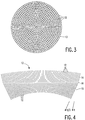
- FIG. 3 and 4 illustrate an embodiment of an MCP in accordance with the invention which comprises a compound MCP 13 having a concavo-convex configuration and consisting of first plano-convex MCP element 14 and a second plano-concave MCP element 15 overlying one another in tandem.
- Each of the MCP elements 14, 15 comprises a radially packed, square pore MCP.
- Figure 3 shows the pore array geometry of the radially packed MCP.
- the pores 12 of square cross-section are arranged in a series of juxtaposed concentric circles, the number of pores lying side by side in each circle being determined by the circle's radius, with one side of each of the pores in each respective circle extending substantially tangentially of the circle.
- the flat sides of the MCP elements 14 and 15 face one another and the pores 12 of the element 14 are aligned with the pores 12 of the element 15 at a plane interface, referenced at 16, such that the pores of the element 14 communicate with respective pores of the element 15.
- the radius R of the plano-convex element 14 is typically 15m, and that of the element 15 is R/3, typically 5m.
- the radially packed array of the MCP 13 may again have a typical diameter of 60mm with the pores in each element 14 and 15 having an overall length of 8mm and being 12.5 ⁇ m square.
- the array In order to collect and focus parallel rays from a source at infinity using a square packed MCP having a grid-like pore geometry, as shown in Figure 1, the array is slumped to a radius of curvature R equal to twice the required focal length f. The grazing angle at the edge of the array is then determined according to the ratio of the diameter of the array to the focal length. To achieve high utilisation of the aperture at a given X-ray energy, it is necessary for the width to length ratio of the pores, and the grazing angle near the edges of the array, which should be close to the critical angle for the rays, to obey a certain relationship. Consequently, the collecting geometric area (aperture) of the array is small. Furthermore, only a fraction of this area is dedicated to the double reflection focused rays with the rest being blocked or lost to the single reflection or straight through rays.
- a much higher fraction of the aperture can be usefully employed using the radial packing scheme for the pores of the array, as in the MCP elements 14 and 15 of figure 3 and 4. Then, unlike the MCP of Figures 1 and 2, the cross-section of the MCP is effectively the same for all azimuthal positions.
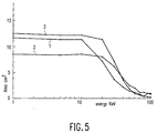
- Figure 5 illustrates the effective, collecting, areas of three plates of like diameter and pore size and packing at different energies of X-rays.
- Curves 1 and 2 are for prior art square packed radially slumped arrays as illustrated in Figures 1 and 2, of radii (focal length) 5 and 1 Om respectively.
- Curve 3 is for a tandem, radially packed configuration as illustrated in Figures 3 and 4 of focal length 5m.
- the graphs show theoretical effective areas after pore surface roughness has been accounted for and illustrate that the improvement brought about by the invention is particularly apparent at harder X-ray frequencies, that is, higher X-ray energy levels. At lower energies the improvement is less pronounced although still significant.
- the MCP elements are formed of lead glass, such as Corning 8161 glass, which can be reduced in hydrogen to give a high surface lead content for improved reflectivity.
- the MCP's may be fabricated by drawing, stacking and etching of glass fibres consisting of an acid soluble core glass and an acid resistant lead glass cladding. Square cross-section fibres are bundled, drawn and fused to form a boule with radially packed pore geometry and the required pore diameter. The boule is then sliced to produce a plate of the required thickness. Slumping to the desired radius of curvature can be achieved by heating the plate to above its softening point between spherical mandrels prior to the final etching stage.
- the MCP may instead comprise a single plate having a radially-packed array of square pores.
- the MCP may be slumped or flat.
- the slumping may perhaps be other than spherical.
Landscapes
- Physics & Mathematics (AREA)
- Spectroscopy & Molecular Physics (AREA)
- Engineering & Computer Science (AREA)
- General Engineering & Computer Science (AREA)
- High Energy & Nuclear Physics (AREA)
- Analysing Materials By The Use Of Radiation (AREA)
- Apparatus For Radiation Diagnosis (AREA)
Description
- This invention relates to micro-channel plates (MCP's). The invention is concerned particularly with MCP's for use in imaging x-rays and particles having equivalent wavelengths.
- MCP's have been utilised to perform a lens function in x-ray and the like imaging applications. X-rays, or, particles reflected at grazing incidence from the internal glass walls of the channels, or pores, of the MCP can be brought to a focus.
- Square pore MCP's have been successfully applied in focusing X-rays or particles having equivalent wavelengths, for example neutrons, and have been used for example in X-ray telescopes. Other possible uses include X-ray lithography, flux concentration for X-ray scattering experiments, neutron focusing, X-ray microscopy and in diagnostic and therapeutic X-ray machines.
- The use of square pore MCPs in X-ray imaging is described in, for example, the paper entitled "X-ray focusing using micro-channel plates" by P. Kaaret et al published in Applied Optics vol. 31, No. 34, pages 7339 to 7343, 1992. In an experimental arrangement described in this paper a flat (planar) MCP is utilised to focus diverging X-rays from a point source located at a finite distance from the MCP to an image. The pores of the MCP are parallel to each other and tilted relative to the surface by a bias angle and the MCP is orientated such that the pore axes are parallel to the optical axis.
- As is mentioned in this paper, square pore MCP's are considered to offer an improvement over MCP's having circular pores as they lead to a significant increase in the intensity of the focused beam which, it is said, is due to the fact that the angles of incidence and reflection are the same regardless of the point of reflection in the square geometry.
- Square pore MCP's for X-ray and the like imaging have also been produced in a spherically slumped configuration in which the axis of each pore is aligned radially with respect to a spherical surface. By arranging that the axes of the pores extend normal to the spherical surface in this manner, parallel rays from a source at infinity can be imaged. The use of such an MCP is reported in the paper entitled "X-ray focussing using microchannel plates" by G. W. Fraser et al published in SPIE Proceeding, Vol. 1546, page 41-52, 1991.
- In these MCP's the pores are square-packed, that is to say, in cross-section, the pores are arranged in othogonal rows and columns, in a grid like pattern.
- We have found that improved results are achieved with a different arrangement.
- According to the present invention there is provided a micro-channel plate comprising an array of square pores which is characterised in that the pores of the array are radially packed.
- The MCP may be slumped, preferably spherically, for imaging, for example, parallel X-rays from a source at infinity, or flat for imaging diverging rays from a source at a finite distance.
- A radially packed, square pore, MCP has been found to provide improved performance compared with that of a square packed, square pore, MCP. Because of the so-called point spread function, a square pore MCP whose pores are arranged in a square grid of rows and columns of pores, gives an image in the form of a cross. With a radially packed, square pore array, the central focus is retained but the cross is lost. The radially packed square pore MCP leads also to a more useful effective aperture.
- In a preferred embodiment the micro-channel plate, suitable for use in focusing parallel X-rays and the like, comprises first and second spherically slumped micro-channel plate elements of different radii of curvature overlying one another with the pores of the first element aligned and communicating with the pores of the second element. The plate may comprise a concavo-convex compound array having a first plano-convex element of radius R and a second plano-concave element of radius less than R, for example R/3. Such a plate will have a greater effective area - a measure of its efficiency at focusing x-rays - than a square packed array, particularly at hard x-ray frequencies.
- One embodiment of a micro-channel plate according to the invention will now be described, by way of example, with reference to the accompanying drawings, in which:-
- Figure 1 is a diagrammatic face-on view of a prior art MCP having a square packed, square pore array;
- Figure 2 is a diagrammatic cross-section through the prior art MCP of Figure 1;
- Figure 3 is a diagrammatic face-on view of an embodiment of MCP according to the invention;
- Figure 4 is a diagrammatic cross-section of the MCP of Figure 3; and
- Figure 5 is a graph showing the effective areas of two prior art plates and an MCP as illustrated in Figures 3 and 4.
- It should be understood that the Figures are merely diagrammatic and are not drawn to scale. Certain dimensions, in particular the size of the pores in relation to the overall MCP dimensions, and the degree of curvature have been greatly exaggerated.
- Figures 1 and 2 illustrate a prior art radially slumped, square packed,
square pore MCP 11 with a radius of curvature R which can for example be 5 or 10 m. Being square packed the MCP has a grid like array of square section pores, or channels, 12 in which theindividual pores 12 are aligned in orthogonal rows and columns. In the diagrammatic illustrations of Figures 1 and 2 the pores are shown greatly enlarged for the sake of clarity. A typical diameter for such an array is 60mm with eachpore 12 being, say, 12.5µm square and having a length of 8mm. Because of the slumping, the pore size at the opposing sides may differ slightly. - As can be seen in Figure 2, the
pores 12 of the spherically slumpedMCP 11 are stacked with their axes extending normal to the spherical surface of the MCP, these axes coinciding at the centre of curvature of the plate. - For more details of square pore MCPs and their use in x-ray focusing applications and the like, reference is invited to the aforementioned publications.
- Figure 3 and 4 illustrate an embodiment of an MCP in accordance with the invention which comprises a
compound MCP 13 having a concavo-convex configuration and consisting of first plano-convex MCP element 14 and a second plano-concave MCP element 15 overlying one another in tandem. Each of theMCP elements - Figure 3 shows the pore array geometry of the radially packed MCP. As can be seen from this figure, the
pores 12 of square cross-section are arranged in a series of juxtaposed concentric circles, the number of pores lying side by side in each circle being determined by the circle's radius, with one side of each of the pores in each respective circle extending substantially tangentially of the circle. The flat sides of theMCP elements pores 12 of theelement 14 are aligned with thepores 12 of theelement 15 at a plane interface, referenced at 16, such that the pores of theelement 14 communicate with respective pores of theelement 15. - As before, the pores of the arrays are shown greatly enlarged for the sake of clarity.
- The radius R of the plano-
convex element 14 is typically 15m, and that of theelement 15 is R/3, typically 5m. - The radially packed array of the
MCP 13 may again have a typical diameter of 60mm with the pores in eachelement - With this MCP in use, for example, in X-ray imaging, rays reflected at grazing incidence from the internal walls of the
pores 12 can be brought to a focus. Normally, when using an MCP, and considering parallel rays, e.g. from a source at infinity, only rays which suffer two reflections of adjacent walls are brought to focus. Single reflection rays produce an aberration in the form of a cross around the true image and those that pass straight through simply add to any diffuse background. - In order to collect and focus parallel rays from a source at infinity using a square packed MCP having a grid-like pore geometry, as shown in Figure 1, the array is slumped to a radius of curvature R equal to twice the required focal length f. The grazing angle at the edge of the array is then determined according to the ratio of the diameter of the array to the focal length. To achieve high utilisation of the aperture at a given X-ray energy, it is necessary for the width to length ratio of the pores, and the grazing angle near the edges of the array, which should be close to the critical angle for the rays, to obey a certain relationship. Consequently, the collecting geometric area (aperture) of the array is small. Furthermore, only a fraction of this area is dedicated to the double reflection focused rays with the rest being blocked or lost to the single reflection or straight through rays.
- A much higher fraction of the aperture can be usefully employed using the radial packing scheme for the pores of the array, as in the
MCP elements element 14, for example, all the pores at a given radius provide the same projected single reflection area of on-axis rays and the rays are brought to a focus at f = R/2. Rays at an angle to the axis are not focused to a point and can lead to circular aberration. This aberration is corrected by introducing a second reflection in the same plane through the use of the second radially packed pore array of theMCP element 15 having a smaller radius of curvature, which, in the case of the embodiment of Figures 3 and 4, is one third that of the first. Paraxial rays are brought to a point focus at f = R/4 with a width corresponding approximately to the pure width. - Figure 5 illustrates the effective, collecting, areas of three plates of like diameter and pore size and packing at different energies of X-rays.
Curves Curve 3 is for a tandem, radially packed configuration as illustrated in Figures 3 and 4 of focal length 5m. The graphs show theoretical effective areas after pore surface roughness has been accounted for and illustrate that the improvement brought about by the invention is particularly apparent at harder X-ray frequencies, that is, higher X-ray energy levels. At lower energies the improvement is less pronounced although still significant. - The MCP elements are formed of lead glass, such as Corning 8161 glass, which can be reduced in hydrogen to give a high surface lead content for improved reflectivity.
- The MCP's, like those with circular channels used for electron multiplication purposes in image intensifiers and the like, may be fabricated by drawing, stacking and etching of glass fibres consisting of an acid soluble core glass and an acid resistant lead glass cladding. Square cross-section fibres are bundled, drawn and fused to form a boule with radially packed pore geometry and the required pore diameter. The boule is then sliced to produce a plate of the required thickness. Slumping to the desired radius of curvature can be achieved by heating the plate to above its softening point between spherical mandrels prior to the final etching stage. For the MCP of Figures 3 and 4, consisting of tandem MCP elements, two plates may be cut from the same boule. Each plate is then slumped to the required radius (R=2f and R= 2f/3). After slumping, the plates can be ground, lapped and polished on their joint plane to provide the necessary channel alignment, following which the two plates are cemented together in alignment.
- Although a square-pore, spherically-slumped, radially packed MCP comprising two MCP elements in tandem has been described in particular, other embodiments are possible. Thus, for example, in another embodiment the MCP may instead comprise a single plate having a radially-packed array of square pores. Depending on whether the MCP is intended to be used for rays, or particles, which are parallel, as, for example, from a source at infinity, or diverging, as, for example, from a source located at a certain distance from the MCP, the MCP may be slumped or flat. Moreover, if slumped, the slumping may perhaps be other than spherical.
- From reading the present disclosure, modifications will be apparent to persons skilled in the art. Such modifications may involve other features which are already known in the field of MCPs and which may be used instead of, or in addition to, features already described herein.
Claims (5)
- A micro-channel plate (13) comprising an array of square pores (12), characterised in that the pores of the array are radially packed.
- A micro-channel plate according to Claim 1, characterised in that the plate (13) is spherically slumped.
- A micro-channel plate according to Claim 2, characterised in that the plate (13) comprises first and second spherically slumped micro-channel plate elements (14, 15) of different radii of curvature overlying one another with the pores of the first element aligned and communicating with the pores of the second element.
- A micro-channel plate according to Claim 3, characterised in that the plate (13) comprises a concavo-convex plate in which the first element (14) is plano-convex and the second element (15) is plano-concave and of a radius less than the radius (R) of the first element.
- A micro-channel plate according to Claim 4, characterised in that the radius of the second element is one third that of the first element.
Applications Claiming Priority (2)
| Application Number | Priority Date | Filing Date | Title |
|---|---|---|---|
| GB939311134A GB9311134D0 (en) | 1993-05-28 | 1993-05-28 | Micro-channel plates |
| GB9311134 | 1993-05-28 |
Publications (2)
| Publication Number | Publication Date |
|---|---|
| EP0626700A1 EP0626700A1 (en) | 1994-11-30 |
| EP0626700B1 true EP0626700B1 (en) | 1997-08-27 |
Family
ID=10736340
Family Applications (1)
| Application Number | Title | Priority Date | Filing Date |
|---|---|---|---|
| EP94303925A Expired - Lifetime EP0626700B1 (en) | 1993-05-28 | 1994-05-31 | Micro-channel plates |
Country Status (4)
| Country | Link |
|---|---|
| US (1) | US5479469A (en) |
| EP (1) | EP0626700B1 (en) |
| DE (1) | DE69405153T2 (en) |
| GB (1) | GB9311134D0 (en) |
Families Citing this family (15)
| Publication number | Priority date | Publication date | Assignee | Title |
|---|---|---|---|---|
| US6271534B1 (en) | 1994-07-08 | 2001-08-07 | Muradin Abubekirovich Kumakhov | Device for producing the image of an object using a flux of neutral or charged particles, and an integrated lens for converting such flux of neutral or charged particles |
| US5727044A (en) * | 1994-07-19 | 1998-03-10 | University Of Leicester | Microchannel plates |
| US5621270A (en) * | 1995-03-22 | 1997-04-15 | Litton Systems, Inc. | Electron window for toxic remediation device with a support grid having diverging angle holes |
| US5604353A (en) * | 1995-06-12 | 1997-02-18 | X-Ray Optical Systems, Inc. | Multiple-channel, total-reflection optic with controllable divergence |
| US5914041A (en) * | 1996-09-03 | 1999-06-22 | Nate International | Channel based reverse osmosis |
| US5869841A (en) * | 1996-12-10 | 1999-02-09 | University Of Chicago | 3-dimensional imaging system using crystal diffraction lenses |
| US6127688A (en) * | 1997-02-07 | 2000-10-03 | The University Of Miami | Iso-energetic intensity modulator for therapeutic electron beams, electron beam wedge and flattening filters |
| US5771270A (en) * | 1997-03-07 | 1998-06-23 | Archer; David W. | Collimator for producing an array of microbeams |
| GB0027759D0 (en) * | 2000-11-14 | 2000-12-27 | Univ Leicester | X-ray generator |
| US7231017B2 (en) * | 2005-07-27 | 2007-06-12 | Physical Optics Corporation | Lobster eye X-ray imaging system and method of fabrication thereof |
| US20070230664A1 (en) * | 2006-04-04 | 2007-10-04 | Oxford Instruments Analytical Oy | Collimator for x-ray spectrometry, and an x-ray spectrometric apparatus |
| JP5606226B2 (en) | 2009-11-30 | 2014-10-15 | キヤノン株式会社 | X-ray monochromator and X-ray spectrometer |
| CN106548821B (en) * | 2016-09-28 | 2018-01-09 | 北方夜视技术股份有限公司 | Micropore optical element with high reflectance inwall and preparation method thereof |
| US10751549B2 (en) * | 2018-07-18 | 2020-08-25 | Kenneth Hogstrom | Passive radiotherapy intensity modulator for electrons |
| CN113532645B (en) * | 2021-06-17 | 2022-07-12 | 北京理工大学 | Large-field-of-view small-aberration lobster eye imaging system |
Family Cites Families (6)
| Publication number | Priority date | Publication date | Assignee | Title |
|---|---|---|---|---|
| US3374380A (en) * | 1965-11-10 | 1968-03-19 | Bendix Corp | Apparatus for suppression of ion feedback in electron multipliers |
| FR2086673A5 (en) * | 1970-04-06 | 1971-12-31 | Labo Electronique Physique | |
| NL7214206A (en) * | 1971-10-20 | 1973-04-25 | ||
| US4271362A (en) * | 1973-07-23 | 1981-06-02 | Republic Steel Corporation | Method and apparatus for detecting a distant object using gamma radiation |
| DE3909147A1 (en) * | 1988-09-22 | 1990-09-27 | Philips Patentverwaltung | ARRANGEMENT FOR MEASURING THE IMPULSE TRANSFER |
| US5231654A (en) * | 1991-12-06 | 1993-07-27 | General Electric Company | Radiation imager collimator |
-
1993
- 1993-05-28 GB GB939311134A patent/GB9311134D0/en active Pending
-
1994
- 1994-05-31 DE DE69405153T patent/DE69405153T2/en not_active Expired - Fee Related
- 1994-05-31 US US08/251,539 patent/US5479469A/en not_active Expired - Fee Related
- 1994-05-31 EP EP94303925A patent/EP0626700B1/en not_active Expired - Lifetime
Also Published As
| Publication number | Publication date |
|---|---|
| EP0626700A1 (en) | 1994-11-30 |
| DE69405153T2 (en) | 1998-02-26 |
| GB9311134D0 (en) | 1993-07-14 |
| US5479469A (en) | 1995-12-26 |
| DE69405153D1 (en) | 1997-10-02 |
Similar Documents
| Publication | Publication Date | Title |
|---|---|---|
| EP0626700B1 (en) | Micro-channel plates | |
| EP0708970B1 (en) | Spherical mirror grazing incidence x-ray optics | |
| US20050185306A1 (en) | Optical reflector element, its method of fabrication, and an optical instrument implementing such elements | |
| JP2526409B2 (en) | X-ray lens | |
| EP2519978B1 (en) | Photovoltaic concentrator with optical stepped lens and method for designing the same | |
| Willingale et al. | The hot and energetic universe: The optical design of the athena+ mirror | |
| US6185278B1 (en) | Focused radiation collimator | |
| EP1688963B1 (en) | X-ray focusing device | |
| EP1060477A1 (en) | Single corner kirkpatrick-baez beam conditioning optic assembly | |
| US7084412B2 (en) | Collector unit with a reflective element for illumination systems with a wavelength of smaller than 193 nm | |
| WO1995033220A1 (en) | Lenses formed by arrays of reflectors | |
| EP0051932A1 (en) | Point focus radiation concentrator | |
| CN112888982B (en) | Multi-channel short-distance imaging device | |
| US6269145B1 (en) | Compound refractive lens for x-rays | |
| US7439492B1 (en) | Nondispersive neutron focusing method beyond the critical angle of mirrors | |
| JP2002239773A (en) | Device and method for semiconductor laser beam machining | |
| US20020021782A1 (en) | Optical assembly for increasing the intensity of a formed X-ray beam | |
| GB2087590A (en) | Reflection rejecting optical train | |
| Beijersbergen et al. | Development of x-ray pore optics: novel high-resolution silicon millipore optics for XEUS and ultralow mass glass micropore optics for imaging and timing | |
| US5727044A (en) | Microchannel plates | |
| US8761346B2 (en) | Multilayer total internal reflection optic devices and methods of making and using the same | |
| WO1992009088A1 (en) | Improved multiple channel configurations for conditioning x-ray or neutron beams | |
| WO2012026572A1 (en) | Light-condensing device, light power generation device, and photothermal conversion device | |
| EP2592626A1 (en) | Efficient monochromator | |
| Mildner | The neutron microguide as a probe for materials analysis |
Legal Events
| Date | Code | Title | Description |
|---|---|---|---|
| PUAI | Public reference made under article 153(3) epc to a published international application that has entered the european phase |
Free format text: ORIGINAL CODE: 0009012 |
|
| AK | Designated contracting states |
Kind code of ref document: A1 Designated state(s): DE FR GB IT NL |
|
| 17P | Request for examination filed |
Effective date: 19950530 |
|
| GRAG | Despatch of communication of intention to grant |
Free format text: ORIGINAL CODE: EPIDOS AGRA |
|
| 17Q | First examination report despatched |
Effective date: 19960823 |
|
| GRAH | Despatch of communication of intention to grant a patent |
Free format text: ORIGINAL CODE: EPIDOS IGRA |
|
| GRAH | Despatch of communication of intention to grant a patent |
Free format text: ORIGINAL CODE: EPIDOS IGRA |
|
| GRAA | (expected) grant |
Free format text: ORIGINAL CODE: 0009210 |
|
| AK | Designated contracting states |
Kind code of ref document: B1 Designated state(s): DE FR GB IT NL |
|
| PG25 | Lapsed in a contracting state [announced via postgrant information from national office to epo] |
Ref country code: IT Free format text: LAPSE BECAUSE OF FAILURE TO SUBMIT A TRANSLATION OF THE DESCRIPTION OR TO PAY THE FEE WITHIN THE PRESCRIBED TIME-LIMIT;WARNING: LAPSES OF ITALIAN PATENTS WITH EFFECTIVE DATE BEFORE 2007 MAY HAVE OCCURRED AT ANY TIME BEFORE 2007. THE CORRECT EFFECTIVE DATE MAY BE DIFFERENT FROM THE ONE RECORDED. Effective date: 19970827 |
|
| REF | Corresponds to: |
Ref document number: 69405153 Country of ref document: DE Date of ref document: 19971002 |
|
| ET | Fr: translation filed | ||
| PLBE | No opposition filed within time limit |
Free format text: ORIGINAL CODE: 0009261 |
|
| STAA | Information on the status of an ep patent application or granted ep patent |
Free format text: STATUS: NO OPPOSITION FILED WITHIN TIME LIMIT |
|
| 26N | No opposition filed | ||
| NLT1 | Nl: modifications of names registered in virtue of documents presented to the patent office pursuant to art. 16 a, paragraph 1 |
Owner name: KONINKLIJKE PHILIPS ELECTRONICS N.V. |
|
| REG | Reference to a national code |
Ref country code: FR Ref legal event code: CD |
|
| REG | Reference to a national code |
Ref country code: GB Ref legal event code: IF02 |
|
| PGFP | Annual fee paid to national office [announced via postgrant information from national office to epo] |
Ref country code: FR Payment date: 20030526 Year of fee payment: 10 |
|
| PGFP | Annual fee paid to national office [announced via postgrant information from national office to epo] |
Ref country code: GB Payment date: 20030529 Year of fee payment: 10 |
|
| PGFP | Annual fee paid to national office [announced via postgrant information from national office to epo] |
Ref country code: NL Payment date: 20030530 Year of fee payment: 10 |
|
| PGFP | Annual fee paid to national office [announced via postgrant information from national office to epo] |
Ref country code: DE Payment date: 20030715 Year of fee payment: 10 |
|
| NLS | Nl: assignments of ep-patents |
Owner name: PANALYTIC B.V. |
|
| REG | Reference to a national code |
Ref country code: GB Ref legal event code: 732E |
|
| REG | Reference to a national code |
Ref country code: FR Ref legal event code: TP |
|
| PG25 | Lapsed in a contracting state [announced via postgrant information from national office to epo] |
Ref country code: GB Free format text: LAPSE BECAUSE OF NON-PAYMENT OF DUE FEES Effective date: 20040531 |
|
| PG25 | Lapsed in a contracting state [announced via postgrant information from national office to epo] |
Ref country code: NL Free format text: LAPSE BECAUSE OF NON-PAYMENT OF DUE FEES Effective date: 20041201 Ref country code: DE Free format text: LAPSE BECAUSE OF NON-PAYMENT OF DUE FEES Effective date: 20041201 |
|
| GBPC | Gb: european patent ceased through non-payment of renewal fee | ||
| PG25 | Lapsed in a contracting state [announced via postgrant information from national office to epo] |
Ref country code: FR Free format text: LAPSE BECAUSE OF NON-PAYMENT OF DUE FEES Effective date: 20050131 |
|
| NLV4 | Nl: lapsed or anulled due to non-payment of the annual fee |
Effective date: 20041201 |
|
| REG | Reference to a national code |
Ref country code: FR Ref legal event code: ST |