EP0625834B1 - Verfahren und Anordnung für eine abhörsichere optische Verbindung - Google Patents
Verfahren und Anordnung für eine abhörsichere optische Verbindung Download PDFInfo
- Publication number
- EP0625834B1 EP0625834B1 EP94850074A EP94850074A EP0625834B1 EP 0625834 B1 EP0625834 B1 EP 0625834B1 EP 94850074 A EP94850074 A EP 94850074A EP 94850074 A EP94850074 A EP 94850074A EP 0625834 B1 EP0625834 B1 EP 0625834B1
- Authority
- EP
- European Patent Office
- Prior art keywords
- optical
- devised
- signal
- proportion
- shot noise
- Prior art date
- Legal status (The legal status is an assumption and is not a legal conclusion. Google has not performed a legal analysis and makes no representation as to the accuracy of the status listed.)
- Expired - Lifetime
Links
Images
Classifications
-
- H—ELECTRICITY
- H04—ELECTRIC COMMUNICATION TECHNIQUE
- H04B—TRANSMISSION
- H04B10/00—Transmission systems employing electromagnetic waves other than radio-waves, e.g. infrared, visible or ultraviolet light, or employing corpuscular radiation, e.g. quantum communication
- H04B10/80—Optical aspects relating to the use of optical transmission for specific applications, not provided for in groups H04B10/03 - H04B10/70, e.g. optical power feeding or optical transmission through water
- H04B10/85—Protection from unauthorised access, e.g. eavesdrop protection
Definitions
- the invention relates to optical transmission systems with associated optical links.
- Tapping of information from connections in different forms of communications networks is a well known problem.
- Electrical connections radiate magnetic and electrical fields which can be tapped by different means.
- Optical connections have the advantage that no magnetic and electrical fields which can be recorded occur outside an optical fibre.
- PPM pulse position modulation
- Encryption of information presupposes that a transmitter and receiver have agreed on the code which will be used. For this to be effective, keys and changing of the codes within, for example, certain time frames is required.
- the methods using encryption presuppose normal sophisticated equipment at the transmitter and receiver ends. There is thus a requirement that security against interception can be achieved without expensive encryption equipment having to be utilized.
- the present invention aims to solve the said problems.
- the present invention relates to a method according to Claim 1 and a system according to Claim 3 for producing an interception-proof transmission between a transmitter and a receiver via an optical connection.
- An unauthorized receiver which connects itself to the connection is assumed to do this by tapping light out of the link. This is done, for example, by the glass fibre which is contained in the link being bent considerably, as a result of which light leaks out of the fibre. The unauthorized party then attempts to decode the information in the tapped light. Due to the fact that the signal contains a large proportion of optical noise in combination with PPM modulation, a large part of the light in the fibre must be taken out for it to be possible to interpret the signal.
- a suitably selected signal/noise ratio means that the proportion of light which is taken out of the fibre by an unauthorized party is high if the information is to be interpretable. If large amounts of light are taken out of a connection, this can be detected at the receiver end in specially arranged monitoring elements.
- monitoring equipment is arranged which, for example, monitors the received optical power. If information is tapped out of the system, the optical power will be changed. The monitoring equipment then registers that a change beyond acceptable limits has taken place and outputs an alarm. Measures with respect to whatever occurred are then taken.
- the signal transmission is combined with error-correcting and error-detecting coding in combination with automatic repeat request (ARQ).
- ARQ automatic repeat request
- a return channel is arranged in which the receiver transfers the automatic repeat request to the transmitter. This makes it possible to use different wavelengths for the channels, which makes it more difficult for an unauthorized interceptor to interpret information. If the return channel is arranged in another fibre or another cable connection, this provides further difficulties to taking any information out of the connection.
- automatic repeat request the possibility of receiving the information correctly at the receiver is increased. An unauthorized interceptor cannot request retransmission without the interception being discovered.
- the arrangement comprises a transmitter and a receiver, and a communications link between them.
- the transmitter is provided with a transmitting element.
- the transmitting element transmits information in the form of an optical signal.
- the optical signal is provided with a high proportion of optical noise.
- the optical noise supplied in the system dominates over other noise sources, for example thermal noise in the receiver.
- the transmitter also orders the information in the information channel in accordance with the pulse position modulation method. Since, in this case, each pulse corresponds to different representations, see Figure 5, the party tapping the information must know the code utilized. If the code is known, it must also be known how the information has been built up and where the pulses begin and end.
- error-detecting codes with automatic repeat request are utilized.
- ARQ automatic repeat request
- the present invention is simple to apply in existing and future optical systems.
- Unauthorized interception requires that a relatively large amount of energy must be taken out of the connection. This means that the receiver can detect that interception is occurring.
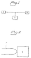
- Figure 1 shows a transmission link with transmitter S and receiver M, and an interceptor A coupled to the system.
- Figure 2 shows a fibre F which has been bent, whereby light is detected by an interceptor A.
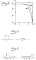
- Figure 3 shows a characteristic of an optical receiver.
- FIG. 4 shows on/off modulation of conventional type
- Figure 5 shows the principle of pulse position modulation.
- the invention relates to a method and an apparatus for establishing interception-proof optical links.
- the invention combines pulse position modulation, PPM, with the signal being given a high degree of optical noise, shot noise. This entails, on the one hand, that a minimum amount of light must be taken out of the connection and, on the other hand, that a selected code according to PPM must be known for the tapped information to be interpretable.
- the information is transmitted from the transmitter in digital form.
- the information can be transferred according to various known principles.
- Figures 4 and 5 show examples of different principles of representation of information. Other representations are possible, but in the text below, the invention is described with utilization of the representation with PPM modulation specified in Figure 5.
- the representation relates to pulse position modulation (PPM).
- PPM pulse position modulation
- n binary digits are transferred due to the fact that the pulse can occur in 2 n different positions in the signal interval.
- the security in the system is increased by n and the ideal (dashed) curve in Figure 3 is approached with a large n.
- the system then has absolute security against tapping. However, a system with a large n is complicated to achieve. In practice, n should be selected in such a manner that an adequate degree of security is obtained.
- Figure 3 shows the probability of transmission errors in relation to how large a part of the signal power is utilized.
- the dashed line specifies an ideal state in which protection against unauthorized interception is very high.
- the remaining curves show corresponding characteristics with respect to PPM and conventional modulation OOK, respectively.
- an unauthorized interceptor takes measures for tapping the light out of the fibre in question. This is done, for example, by bending the fibre according to Figure 2 substantially, as a result of which light leaks out. The interceptor then arranges elements which sense the light and convert it into interpretable information. So that the interceptor will be not be discovered, the quantities of the energy content in the signal drained out of the system should not be such that the normal functions of the system are endangered. Furthermore, the energy tapping must be so low that any detection arrangements in the system do not register the tapping.
- the optical noise is selected to be so strong that it dominates over other noise sources, such as thermal noise in the receiver and so forth.
- the number of time slots which is used in PPM is also related to the possibility of detecting meaningful information.
- ARQ automatic repeat request
- the receiver detects received signals and determines if the reception was correct. On indication that the information has not been received correctly, an automatic repeat request is sent to the transmitter about correcting or retransmitting the current section. Due to the fact that PPM is used, the interceptor has little possibility of correctly interpreting the transferred information. In contrast to the legal user, he cannot request retransmission of a message which has been detected as faulty. Such an automatic repeat request from someone who is intercepting the connection in an unauthorized manner would inevitably reveal that an illegal activity is taking place. The party intercepting the connection will be able to tap information which is transmitted on the return channel provided the frequency of the return channel is known. If the return channel is transmitted on an optical fibre other than the one for information from the transmitter, such interception is rendered more difficult.
- the interceptor derives little benefit from attempting to intercept the return channel. This only contains the request for retransmission by the receiver. All information which needs to be protected is transmitted via the main connection.
- P(C) is the probability that the interceptor will be able to gain information out of the tapped signal, and the possibility is non-existent with such small values of P(C).
- the invention thus provides a very high security against unauthorized interception.
Landscapes
- Engineering & Computer Science (AREA)
- Computer Security & Cryptography (AREA)
- Physics & Mathematics (AREA)
- Electromagnetism (AREA)
- Computer Networks & Wireless Communication (AREA)
- Signal Processing (AREA)
- Optical Communication System (AREA)
- Dc Digital Transmission (AREA)
Claims (9)
- Verfahren in einem Kommunikationssystem zum Herstellen von Kommunikation zwischen einem Sender (S) und einem Empfänger (M) zum Errichten einer abhörsicheren optischen Strecke, wobei optische Signale mit einem hohen Anteil an Schrotrauschen auf der optischen Strecke übertragen werden, mit dem Schritt des Erzeugens eines Signals mit optischem Schrotrauschen (shot noise) in einem solchen Anteil, daß das Schrotrauschen gegenüber anderen Rauschquellen vorherrscht, gekennzeichnet durch den Schritt des Modulierens des Slgnals gemäß dem Pulspositions-Modulationsverfahren, PPM.
- Verfahren nach Anspruch 1, bei dem die Signalübertragung kombiniert ist mit Fehlerdetektionscodierung in Kombination mit einer automatischen Wiederholungsanforderung ARQ.
- System mit einem sendenden (S) und einem empfangenden (M) Elementen zum Herstellen von abhörsicherer Kommunikation auf einer optischen Strecke, wobei optische Signale mit einem hohen Anteil an Schrotrauschen auf der optischen Strecke übertragen werden und das sendende Element (S) so eingerichtet ist, daß es ein optisches Signal aussendet, das optisches Schrotrauschen in solchem Anteil aufweist, daß das Schrotrauschen gegenüber anderen Rauschquellen vorherrscht
dadurch gekennzeichnet, daß das sendende Element (S) ferner so ausgestaltet ist, daß es das Signal mit Pulspositionsmodulation PPM moduliert. - System nach Anspruch 3, bei dem das sendende Element (S) so ausgestaltet ist, daß es einen fehlerdetektierenden Code benutzt und eine automatische Wiederholungsanforderung von dem empfangenden Element empfängt und auf sie reagiert.
- System nach Anspruch 3 oder 4, bei dem das empfangende Element (M) so ausgestaltet ist, daß es den Empfang des Signals mit einer Anwendung eines fehlerdetektierenden Codes in Kombination mit der automatischen Wiederholungsanforderung ARQ kombiniert.
- Sender (S) zum Senden eines optischen Signals mit hohem Anteil an Schrotrauschen auf einer optischen Strecke, der so ausgestaltet ist, daß er ein optisches Signal aussendet, welches optisches Schrotrauschen in solchem Anteil enthält, daß das Schrotrauschen gegenüber anderen Rauschquellen vorherrscht, dadurch gekennzeichnet, daß er so ausgestaltet ist, daß er das Signal mit Pulspositionsmodulation PPM moduliert.
- Sender (S) nach Anspruch 6, der ferner so ausgestaltet ist, daß er einen fehlerdetektieren Code benutzt und eine automatische Wiederholungsanforderung von dem empfangenden Element empfängt und darauf reagiert.
- Empfänger (M) zum Empfangen eines optischen Signals mit hohem Anteil an Schrotrauschen auf einer optischen Strecke, der so ausgestaltet ist, daß er ein optisches Signal empfängt, welches optisches Schrotrauschen in solchem Anteil enthält, daß das Schrotrauschen gegenüber anderen Rauschquellen vorherrscht, dadurch gekennzeichnet, daß er so ausgestaltet ist, daß er das optische Signal, welches mit Pulspositionsmudulations PPM moduliert ist, empfängt.
- Empfänger (M) gemäß Anspruch 8, der ferner so ausgestaltet ist, daß er einen fehlerdetektierenden Code in Kombination mit automatischer Wiederholungsanforderung ARQ benutzt.
Applications Claiming Priority (2)
| Application Number | Priority Date | Filing Date | Title |
|---|---|---|---|
| SE9301710 | 1993-05-18 | ||
| SE9301710A SE500286C2 (sv) | 1993-05-18 | 1993-05-18 | Metod och anordning för att anordna avlyssningssäker optisk länk |
Publications (2)
| Publication Number | Publication Date |
|---|---|
| EP0625834A1 EP0625834A1 (de) | 1994-11-23 |
| EP0625834B1 true EP0625834B1 (de) | 2000-01-12 |
Family
ID=20389984
Family Applications (1)
| Application Number | Title | Priority Date | Filing Date |
|---|---|---|---|
| EP94850074A Expired - Lifetime EP0625834B1 (de) | 1993-05-18 | 1994-05-02 | Verfahren und Anordnung für eine abhörsichere optische Verbindung |
Country Status (4)
| Country | Link |
|---|---|
| US (1) | US5559623A (de) |
| EP (1) | EP0625834B1 (de) |
| DE (1) | DE69422547T2 (de) |
| SE (1) | SE500286C2 (de) |
Families Citing this family (6)
| Publication number | Priority date | Publication date | Assignee | Title |
|---|---|---|---|---|
| US6118565A (en) * | 1997-09-30 | 2000-09-12 | Lucent Technologies Inc. | Coherent optical communication system |
| US20140186033A1 (en) * | 2012-12-28 | 2014-07-03 | Alcatel-Lucent Usa Inc. | Secure data transmission via spatially multiplexed optical signals |
| US10784969B2 (en) * | 2016-02-18 | 2020-09-22 | Apriori Network Systems, Llc. | Secured fiber link system |
| US10763962B2 (en) | 2016-02-18 | 2020-09-01 | Apriori Network Systems, Llc. | Secured fiber link system |
| US10284288B2 (en) | 2016-02-18 | 2019-05-07 | Apriori Network Systems, Llc | Secured fiber link system |
| US11985457B2 (en) * | 2019-08-02 | 2024-05-14 | Nippon Telegraph And Telephone Corporation | Communication apparatus and communication method |
Family Cites Families (12)
| Publication number | Priority date | Publication date | Assignee | Title |
|---|---|---|---|---|
| US4217488A (en) * | 1977-01-21 | 1980-08-12 | Bell Telephone Laboratories, Incorporated | Secure optical communication components, method, and system |
| US4166212A (en) * | 1977-06-03 | 1979-08-28 | International Standard Electric Corporation | Recirculating optical delay line |
| GB2060869B (en) * | 1979-10-16 | 1983-11-02 | Standard Telephones Cables Ltd | Secure optical data systems |
| US4616898A (en) * | 1980-03-31 | 1986-10-14 | Polaroid Corporation | Optical communication systems using raman repeaters and components therefor |
| US4435850A (en) * | 1982-02-16 | 1984-03-06 | International Telephone And Telegraph Corporation | Secure fiber optic data transmission system |
| DE3379767D1 (en) * | 1982-09-02 | 1989-06-01 | British Telecomm | Optical communication |
| SE438396B (sv) * | 1983-09-01 | 1985-04-15 | Ericsson Telefon Ab L M | Anordning for att detektera avtappning av ljusenergi fran optiska fibrer |
| GB2157523A (en) * | 1984-04-09 | 1985-10-23 | Marconi Co Ltd | Secure optical communication system |
| US4648133A (en) * | 1984-08-07 | 1987-03-03 | The Unites States Of America As Represented By The Administrator Of The National Aeronautics And Space Administration | Synchronization tracking in pulse position modulation receiver |
| SE459052B (sv) * | 1987-09-09 | 1989-05-29 | Foersvarets Forskningsanstalt | Saett att detektera yttre paaverkan paa en optisk kabel |
| GB8928699D0 (en) * | 1989-12-20 | 1990-02-28 | Int Computers Ltd | Data communications system |
| US5165091A (en) * | 1991-03-20 | 1992-11-17 | Nec America Inc. | Firmware download from a remote terminal to an optical network terminal in a digital loop carrier system |
-
1993
- 1993-05-18 SE SE9301710A patent/SE500286C2/sv unknown
-
1994
- 1994-05-02 DE DE69422547T patent/DE69422547T2/de not_active Expired - Fee Related
- 1994-05-02 EP EP94850074A patent/EP0625834B1/de not_active Expired - Lifetime
- 1994-05-16 US US08/242,850 patent/US5559623A/en not_active Expired - Lifetime
Also Published As
| Publication number | Publication date |
|---|---|
| SE9301710L (sv) | 1994-05-30 |
| DE69422547D1 (de) | 2000-02-17 |
| DE69422547T2 (de) | 2000-06-29 |
| SE500286C2 (sv) | 1994-05-30 |
| US5559623A (en) | 1996-09-24 |
| EP0625834A1 (de) | 1994-11-23 |
| SE9301710D0 (sv) | 1993-05-18 |
Similar Documents
| Publication | Publication Date | Title |
|---|---|---|
| US5289476A (en) | Transmission mode detection in a modulated communication system | |
| EP0200704B1 (de) | Sicherheitsanordnung für Ladeprogrammkanal in einem Datenübertragungsnetzwerk | |
| US4847842A (en) | SM codec method and apparatus | |
| US6219386B1 (en) | Frameless reed-solomon coding system and method | |
| US6177861B1 (en) | System for short range wireless data communication to inexpensive endpoints | |
| EP1168633B1 (de) | Verfahren und Vorrichtung zur Dekodierung von Blockcodes | |
| CN101779190B (zh) | 信息传输和综合保护的方法 | |
| CN1171416C (zh) | 调制消息鉴权系统和方法 | |
| EP0086482B1 (de) | Kommunikationssystem für digitale Signale | |
| SA94150033B1 (ar) | طريقة ونظام لزيادة الاعتمادية على التردد لنظم الاتصالات ذات التردد المتعدد | |
| EP0625834B1 (de) | Verfahren und Anordnung für eine abhörsichere optische Verbindung | |
| EP0677937B1 (de) | Verfahren zur Auslöschungserkennung in einem Mehrträgerdatenübertragungssystem | |
| EP0976285A2 (de) | Signalisierungsverfahren und digitales funksystem | |
| CA2208660A1 (en) | Data transmission device | |
| EP1300978B1 (de) | Verfahren zur Übertragung von Signalisierungsinformationen über zwei Kanälen | |
| Kamakura et al. | A new modulation scheme using asymmetric erorr-correcting codes embedded in optical orthogonal codes for optical CDMA | |
| Ohtsuki et al. | Overlapping multi-pulse pulse position modulation in optical direct detection channel | |
| US5077794A (en) | Dual framing bit sequence alignment apparatus and method | |
| RU2239951C2 (ru) | Способ передачи дискретной информации в системах с обратной связью | |
| Shalaby | Performance of uncoded overlapping PPM under communication constraints | |
| RU2829498C1 (ru) | Способ защищенной передачи информации по каналу связи и система для его осуществления | |
| RU2027311C1 (ru) | Способ передачи и приема с обеспечением подлинности сообщения | |
| JPS6234309B2 (de) | ||
| Servin | Telecommunications: Transmission and network architecture | |
| RU2264647C1 (ru) | Способ адаптивной передачи информации |
Legal Events
| Date | Code | Title | Description |
|---|---|---|---|
| PUAI | Public reference made under article 153(3) epc to a published international application that has entered the european phase |
Free format text: ORIGINAL CODE: 0009012 |
|
| 17P | Request for examination filed |
Effective date: 19940902 |
|
| AK | Designated contracting states |
Kind code of ref document: A1 Designated state(s): CH DE FR GB LI NL |
|
| 17Q | First examination report despatched |
Effective date: 19971013 |
|
| GRAG | Despatch of communication of intention to grant |
Free format text: ORIGINAL CODE: EPIDOS AGRA |
|
| GRAG | Despatch of communication of intention to grant |
Free format text: ORIGINAL CODE: EPIDOS AGRA |
|
| GRAH | Despatch of communication of intention to grant a patent |
Free format text: ORIGINAL CODE: EPIDOS IGRA |
|
| GRAH | Despatch of communication of intention to grant a patent |
Free format text: ORIGINAL CODE: EPIDOS IGRA |
|
| GRAA | (expected) grant |
Free format text: ORIGINAL CODE: 0009210 |
|
| AK | Designated contracting states |
Kind code of ref document: B1 Designated state(s): CH DE FR GB LI NL |
|
| PG25 | Lapsed in a contracting state [announced via postgrant information from national office to epo] |
Ref country code: LI Free format text: LAPSE BECAUSE OF FAILURE TO SUBMIT A TRANSLATION OF THE DESCRIPTION OR TO PAY THE FEE WITHIN THE PRESCRIBED TIME-LIMIT Effective date: 20000112 Ref country code: CH Free format text: LAPSE BECAUSE OF FAILURE TO SUBMIT A TRANSLATION OF THE DESCRIPTION OR TO PAY THE FEE WITHIN THE PRESCRIBED TIME-LIMIT Effective date: 20000112 |
|
| REG | Reference to a national code |
Ref country code: CH Ref legal event code: EP |
|
| REF | Corresponds to: |
Ref document number: 69422547 Country of ref document: DE Date of ref document: 20000217 |
|
| ET | Fr: translation filed | ||
| REG | Reference to a national code |
Ref country code: CH Ref legal event code: PL |
|
| PLBE | No opposition filed within time limit |
Free format text: ORIGINAL CODE: 0009261 |
|
| STAA | Information on the status of an ep patent application or granted ep patent |
Free format text: STATUS: NO OPPOSITION FILED WITHIN TIME LIMIT |
|
| 26N | No opposition filed | ||
| PGFP | Annual fee paid to national office [announced via postgrant information from national office to epo] |
Ref country code: NL Payment date: 20010531 Year of fee payment: 8 |
|
| REG | Reference to a national code |
Ref country code: GB Ref legal event code: IF02 |
|
| PG25 | Lapsed in a contracting state [announced via postgrant information from national office to epo] |
Ref country code: NL Free format text: LAPSE BECAUSE OF NON-PAYMENT OF DUE FEES Effective date: 20021201 |
|
| NLV4 | Nl: lapsed or anulled due to non-payment of the annual fee |
Effective date: 20021201 |
|
| PGFP | Annual fee paid to national office [announced via postgrant information from national office to epo] |
Ref country code: DE Payment date: 20080523 Year of fee payment: 15 |
|
| PGFP | Annual fee paid to national office [announced via postgrant information from national office to epo] |
Ref country code: GB Payment date: 20080522 Year of fee payment: 15 |
|
| GBPC | Gb: european patent ceased through non-payment of renewal fee |
Effective date: 20090502 |
|
| REG | Reference to a national code |
Ref country code: FR Ref legal event code: ST Effective date: 20100129 |
|
| PG25 | Lapsed in a contracting state [announced via postgrant information from national office to epo] |
Ref country code: FR Free format text: LAPSE BECAUSE OF NON-PAYMENT OF DUE FEES Effective date: 20090602 |
|
| PGFP | Annual fee paid to national office [announced via postgrant information from national office to epo] |
Ref country code: FR Payment date: 20080425 Year of fee payment: 15 |
|
| PG25 | Lapsed in a contracting state [announced via postgrant information from national office to epo] |
Ref country code: GB Free format text: LAPSE BECAUSE OF NON-PAYMENT OF DUE FEES Effective date: 20090502 |
|
| PG25 | Lapsed in a contracting state [announced via postgrant information from national office to epo] |
Ref country code: DE Free format text: LAPSE BECAUSE OF NON-PAYMENT OF DUE FEES Effective date: 20091201 |