EP0625591B1 - Elektrolyseur - Google Patents
Elektrolyseur Download PDFInfo
- Publication number
- EP0625591B1 EP0625591B1 EP94106755A EP94106755A EP0625591B1 EP 0625591 B1 EP0625591 B1 EP 0625591B1 EP 94106755 A EP94106755 A EP 94106755A EP 94106755 A EP94106755 A EP 94106755A EP 0625591 B1 EP0625591 B1 EP 0625591B1
- Authority
- EP
- European Patent Office
- Prior art keywords
- electrolyzer
- chamber
- gas
- projections
- recesses
- Prior art date
- Legal status (The legal status is an assumption and is not a legal conclusion. Google has not performed a legal analysis and makes no representation as to the accuracy of the status listed.)
- Expired - Lifetime
Links
Images
Classifications
-
- C—CHEMISTRY; METALLURGY
- C25—ELECTROLYTIC OR ELECTROPHORETIC PROCESSES; APPARATUS THEREFOR
- C25B—ELECTROLYTIC OR ELECTROPHORETIC PROCESSES FOR THE PRODUCTION OF COMPOUNDS OR NON-METALS; APPARATUS THEREFOR
- C25B15/00—Operating or servicing cells
- C25B15/08—Supplying or removing reactants or electrolytes; Regeneration of electrolytes
-
- C—CHEMISTRY; METALLURGY
- C25—ELECTROLYTIC OR ELECTROPHORETIC PROCESSES; APPARATUS THEREFOR
- C25B—ELECTROLYTIC OR ELECTROPHORETIC PROCESSES FOR THE PRODUCTION OF COMPOUNDS OR NON-METALS; APPARATUS THEREFOR
- C25B9/00—Cells or assemblies of cells; Constructional parts of cells; Assemblies of constructional parts, e.g. electrode-diaphragm assemblies; Process-related cell features
- C25B9/70—Assemblies comprising two or more cells
- C25B9/73—Assemblies comprising two or more cells of the filter-press type
Definitions
- the present invention relates to filter-press electrolyzers and, more particularly, to a filter-press electrolyzer which is characterized by the arrangement of partitions that divide the electrolyte between a pair of adjacent electrode chambers.
- Filter-press electrolyzers are widely used for the electrolytic production of organic substances, the electrolysis of brine, etc., including the production of chlorine and caustic soda by the electrolysis of salt.
- Filter-press electrolyzers used for the electrolysis of salt which is a typical example of electrolytic processes that use a filter-press electrolyzer, include two different types, that is, a bipolar filter-press electrolyzer and a monopolar filter-press electrolyzer.
- the bipolar filter-press electrolyzer is arranged as follows: A multiplicity of bipolar electrolyzer units, which are formed by electrically and mechanically connecting together a pair of anode and cathode chambers divided by a partition, are stacked with a cation-exchange membrane interposed between each pair of adjacent units.
- an end electrode chamber unit having an anode on one side thereof is stacked on one end of the stack of the electrolyzer units, while an end electrode chamber having a cathode on one side thereof is stacked on the other end, and the resulting stack is fixed by a hydraulic press or other similar device.
- the monopolar filter-press electrolyzer is constructed such that a multiplicity of anode chamber units and cathode chamber units, each having the same electrode on each side of an electrode chamber frame, are stacked with a cation-exchange membrane interposed between each pair of adjacent units, and an electrode chamber unit having an anode on one side thereof is stacked on one end of the stack of the units, while an electrode chamber unit having a cathode on one side thereof is stacked on the other end of the stack.
- the electrode chamber units in the monopolar filter-press electrolyzer are each provided with downcomers, ribs, etc. for reinforcing the electrode chamber frame and also for promoting the circulation of the electrolyte, and the electrodes are attached to the ribs or the like. Usually, these electrode chamber units have no partition for dividing the electrolyte.
- the electrode chamber units of the bipolar filter-press electrolyzer are provided with partitions for dividing the anode and cathode chambers and also for transmitting the electrolytic current.
- Diaphragms that divide a pair of anode and cathode chambers are provided with an anode and a cathode, respectively. Either of the anode and cathode chambers is placed in an acidic environment, and the other in a reducing environment, depending upon the desired electrolytic reaction.
- salt which is a typical electrolytic process that uses an ion-exchange membrane, chlorine is formed at the anode, while highly concentrated sodium hydroxide and hydrogen are formed at the cathode.
- the anode chamber is formed of a thin-film forming metal, e.g., titanium, tantalum, zirconium, etc., which has high resistance to corrosion from chlorine or the like, or an alloy of such a metal. Under the atmosphere in the cathode chamber, titanium absorbs hydrogen and becomes brittle. Therefore, titanium, which has high resistance to corrosion, cannot be used for the cathode chamber.
- a thin-film forming metal e.g., titanium, tantalum, zirconium, etc.
- a ferrous metal or alloy e.g., iron, nickel, stainless steel, etc.
- Electrical joint can be formed by defining each electrode chamber by a partition of a metallic material and joining the partitions together.
- titanium that constitutes the anode chamber is welded directly to a ferrous metal, e.g., iron, nickel, stainless steel, etc., which constitutes the cathode chamber, the titanium and the ferrous metal form an intermetallic compound. Therefore, it is impossible to obtain a joint structure having practical strength.
- Japanese Patent Application Post-Exam Publication No. 53-5880 (1978) discloses a technique wherein a member of the anode chamber and a member of the cathode chamber are joined together by using a bolt that extends through a partition made of a synthetic resin material.
- Japanese Patent Application Post-Exam Publication No. 52-32866 (1977) discloses a technique wherein a partition is formed from a plate-shaped member made of a ferrous metal and titanium which are joined by explosive welding, and ribs are welded to both surfaces of the partition, and then an anode and a cathode are welded to the ribs.
- Japanese Patent Application Post-Exam Publication No. 56-36231 (1981) uses a composite material formed by joining together titanium and iron with copper sandwiched therebetween. The titanium of the composite material is welded to titanium that constitutes an anode-side partition of a bipolar electrolyzer unit, and the iron of the composite material is similarly welded to a cathode-side partition made of a ferrous metal.
- ribs are connected to a partition, and an electrode is attached to the ribs by welding or other similar method. With this arrangement, however, a voltage drop due to the ribs is unavoidable. In addition, it is necessary to use a special method for joining together the cathode-side metal and the anode-side metal.
- a bipolar electrolyzer has been proposed as Japanese Patent Application Laid-Open (KOKAI) No. 03-249189 (1991) [Japanese Patent Application No. 02-45855 (1990)], which includes an electrolyzer unit having a partition plate formed from two plates pressed to have recesses and projections, which fit to each other, and electrodes are joined to the projections on both sides of the partition plate, thereby providing a simplified structure and facilitating the process for producing the electrolyzer.
- An effective way of making the electrolyte concentration or temperature uniform is to allow the electrolyte to be uniformly supplied to the electrode chamber.
- an electrolyzer frame member is provided in the lower part of the electrolyzer unit, and it is therefore impossible to provide a device for dispersing the electrolyte.
- a gas-liquid separating device for the electrolyte in the upper part of the electrolyzer unit.
- the present inventors have previously proposed an electrolyzer unit formed by pressing flat plates and also proposed an electrolyzer wherein an electrolyte dispersing and feeding chamber is provided in the lower part of an electrolyzer unit, and a gas-liquid separating chamber is provided in the upper part of the unit, in Japanese Patent Application Nos. 03-154687 (1991), 03-154688 (1991) and 03-160260 (1991) (U.S. Patent Application Serial No. 07/904251), etc.
- the quantities of the electrolyte and the generated gas immediately before they are discharged from the electrode chamber to the gas-liquid separating chamber provided in the upper part of the chamber are uniformly distributed in the horizontal direction of the electrolyzer.
- the flow rate of the fluid comprised of a gas, a gas-liquid multi-phase flow, a liquid, etc. increases as the fluid approaches the discharge opening.
- the speed of the fluid in the chamber increases, and the pressure loss also increases.
- An object of the present invention is to provide an electrolyzer having a gas-liquid separating chamber provided in the upper part of an electrolyzer unit formed by pressing flat plates.
- the electrolyzer is arranged to prevent vibration of the ion-exchange membrane due to the fluctuation of pressure in the electrolytic chamber caused by pulsation of the gas-liquid multi-phase flow or the like which occurs inside the gas-liquid separating chamber, thereby stabilizing the operation of the electrolyzer and also enabling the ion-exchange membrane to be stably used for a long period of time.
- the present invention provides an electrolyzer including a vertical electrolyzer unit which has a partition plate formed by superimposing a pair of anode- and cathode-side partitions provided with mutually fittable recesses and projections, and an electrode plate connected to the projections on each side of the partition plate to define an electrolytic chamber, and which further has in the upper part thereof a gas-liquid separating chamber for an electrolyte which is formed from a member integral with each of the partitions.
- the area of a cross-section of the gas-liquid separating chamber taken along a plane perpendicular to a flow passage inside the gas-liquid separating chamber which leads to a discharge opening is larger at a part closer to the discharge opening than at a part remoter from the discharge opening.
- the electrolyzer may further have in the lower part of the electrolyzer unit an electrolyte dispersing and feeding chamber formed from a member integral with each of the partitions.
- the electrolyzer of the present invention includes a vertical electrolyzer unit which has a partition plate formed by superimposing a pair of anode- and cathode-side partitions provided with mutually fittable recesses and projections, and an electrode plate connected to the projections on each side of the partition plate to define an electrolytic chamber, wherein a gas-liquid separating chamber is formed in the upper part of the electrolyzer unit such that the area of a cross-section of the gas-liquid separating chamber taken along a plane perpendicular to a flow passage inside the gas-liquid separating chamber which leads to a discharge opening is larger at a part closer to the discharge opening than at a part remoter from the discharge opening.
- the ion-exchange membrane that divides the cathode and anode chambers can be prevented from being damaged by vibration or the like.
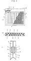
- Fig. 1(A) is a plan view showing one embodiment of the electrolyzer according to the present invention.
- Fig. 1(B) is a sectional view taken along the line A-A in Fig. 1(A).
- Fig. 1(C) is a fragmentary vertical sectional view of the embodiment.
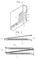
- Fig. 2 is a partly cutaway perspective view of a gas-liquid separating chamber in the embodiment of the present invention.
- Figs. 3(A) and 3(B) are sectional views showing gas-liquid separating chambers in the present invention.
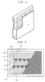
- Fig. 4 shows an electrolyte dispersing and feeding chamber provided in the lower part of an electrolyzer unit in the present invention.
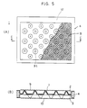
- Figs. 5(A) and 5(B) show another example of recesses and projections provided on partitions in the present invention.
- Fig. 6 shows still another example of the recesses and projections provided on the partitions.
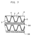
- Fig. 7 is a fragmentary sectional view showing a pair of adjacent electrolyzer units joined together when an electrolyzer is set up by stacking a multiplicity of electrolyzer units.
- Fig. 1(A) is a partly cutaway plan view showing one embodiment of the electrolyzer according to the present invention as viewed from the anode side.
- Fig. 1(B) is a sectional view taken along the line A-A in Fig. 1(A).
- Fig. 1(C) is a fragmentary vertical sectional view of the embodiment.
- An electrolyzer unit 1 has an anode-side partition 2 which is produced by forming in a pan-shaped configuration a thin plate of a metallic material selected from among thin-film forming metals, e.g., titanium, zirconium, tantalum, etc., and alloys of these metals.
- a cathode-side partition 3 is similarly produced by forming a thin plate of iron, nickel, stainless steel, etc.
- the two partitions 2 and 3 are attached to a frame 4 of the electrolyzer.
- the partitions 2 and 3 are formed with recesses and projections, which fit to each other. More specifically, the anode-side partition 2 is provided with groove-shaped recesses and projections 5 and 6.
- the cathode-side partition 3 is similarly provided with groove-shaped recesses and projections 7 and 8 at positions where the recesses 7 and the projections 8 fit to the projections 6 and the recesses 5, respectively.
- An anode 9 is connected to the projections 6 of the anode-side partition 2 by welding or other similar method.
- the anode 9 is made, for example, of an expanded metal plate or a porous plate, which is formed with an anodic activation coating of an oxide of a platinum group metal or the like.
- a cathode 10 is connected to the projections 8 of the cathode-side partition 3 by welding or other similar method.
- the cathode 10 is made, for example, of an expanded metal plate or a porous plate, which is formed with a cathodic activation coating of a metallic substance selected from nickel and platinum metals.
- Gas-liquid separating chambers 11 are provided in the upper part of the electrolyzer unit 1.
- the gas-liquid separating chambers 11 are formed by bending the anode-side partition 2 and the cathode-side partition 3 as follows:
- the partitions 2 and 3 which vertically extend so as to wrap the frame 4 are each bent at right angles so as to extend along an imaginary horizontal straight line toward the side where the electrode 9 or 10 is provided, and further bent at right angles with a length corresponding to the thickness of the associated electrode chamber so that the outer surface of the resulting gas-liquid separating chamber forms a flange surface 12 of the electrolyzer unit 1.
- the distal ends 13 of the partitions 2 and 3 are partially connected to the respective electrodes 9 and 10, thereby fixing the electrodes 9 and 10.
- Communicating passages 14 are provided between each gas-liquid separating chamber 11 and the associated electrode chamber in order to increase the efficiency of gas-liquid separation.
- Fig. 2 is a fragmentary perspective view showing one gas-liquid separating chamber 11 with a part thereof cut away.
- the partition 2 (in the illustrated example) is subjected to forming process to provide the communicating passages 14 and also joint surfaces 15 which are joined to the reverse side of the flange surface 12 of the electrolyzer unit 1 to ensure the required mechanical strength for the electrolyzer unit 1.
- the partition 2 is formed with a recess 16 for receiving the frame 4, and an end portion of the gas-liquid separating chamber 11 is provided with a discharge opening for taking out the electrolyte and generated gas from the electrolyzer.
- Fig. 3(A) is a sectional view showing the structure of a gas-liquid separating chamber in the present invention.
- the spacing between wall surfaces 17 and 18 that constitute a gas-liquid separating chamber is larger at a portion closer to a discharge opening 19 than at a portion remoter from the discharge opening 19. Accordingly, the cross-sectional area becomes larger as the distance to the discharge opening 19 decreases.
- Fig. 3(B) is a sectional view showing an anode-side gas-liquid separating chamber 20 and a cathode-side gas-liquid separating chamber 21, which are stacked with the respective slant surfaces brought into contact with each other so that the overall thickness of the two gas-liquid separating chambers 20 and 21 is the same as the thickness of the electrolyzer unit, thereby enabling the outer surfaces of the gas-liquid separating chambers 20 and 21 to function as flange surfaces of the electrolyzer unit when an electrolyzer is set up.
- Anode- and cathode-side partitions are formed with recesses and projections by using a conventional press machine one by one.
- the anode- and cathode-side partitions may have the same configuration, the same press die can be used for them. Thus, it is necessary to prepare only one press die.
- a pair of anode- and cathode-side partitions may be joined directly by spot welding.
- the two partitions may be joined with an electrically conductive grease interposed therebetween by fitting the recesses and the projections to each other, thereby forming electrical and mechanical joint, without employing a permanent connecting method such as welding.
- the arrangement may be such that an electrolyzer is set up by stacking electrolyzer units, and the inside of each electrode chamber is pressurized so that a pressure difference is produced between the inside and outside of the anode- and cathode-side partitions, thereby enabling the two partitions to come in contact with each other even more effectively.
- the arrangement may also be such that the space formed between the two partitions and the electrode chamber frame is hermetically sealed, and the pressure in this space is reduced to produce a pressure difference between the space and the electrode chambers, thereby enabling the two partitions to come in contact with each other even more effectively.
- an electrolyte dispersing and feeding chamber may be formed in the lower part of the electrolyzer unit so that the electrolyte is uniformly fed into an electrode chamber, as shown in Fig. 4.
- the electrolyte dispersing and feeding chamber may be formed in the same way as in the case of the gas-liquid separating chamber. That is, a partition that vertically extends so as to wrap the electrolyzer frame is bent at right angles along an imaginary horizontal straight line toward the side where the electrode is provided, and further bent at right angles with a length corresponding to the thickness of the electrode chamber so that the outer surface of the resulting electrolyte dispersing and feeding chamber forms a flange surface 12 of the electrolyzer unit. Further, the distal end of the partition is partially connected to the electrode to fix the latter.
- Passages having a small cross-sectional area are provided between the electrolyte dispersing and feeding chamber and the electrode chamber so that the electrolyte can be fed into the electrode chamber at high speed.
- Figs. 5(A) and 5(B) show another example of the recesses and projections provided on the partitions in the electrolyzer.
- Fig. 5(A) is a partly cutaway plan view of the electrolyzer
- Fig. 5(B) is a sectional view taken along the line C-C in Fig. 5(A).
- bowl-shaped recesses and projections 31 are formed in place of the groove-shaped recesses and projections as shown in Fig. 1.
- recesses and projections may be provided in three regions, i.e., an upper region 22, a central region 23, and a lower region 24, of a partition.
- the recesses and projections in each region are formed in the shape of elongated recesses 25 and elongated projections 26, which extend vertically of the electrolyzer unit.
- communicating portions 27 are formed between each pair of adjacent regions to provide communication between the adjacent elongated recesses 25 and also provide communication between the elongated recesses 25 in each pair of adjacent regions.
- the electrolyte is introduced into the electrode chamber from the bottom thereof, and rises through the elongated recesses 25 in the electrode chamber, as shown by the arrows, together with a gas generated in the electrolyzer.
- the electrolyte further rises while changing the flow path from the communicating portions 27 to the left and right elongated recesses 25. In the process of rising, mixing of the components of the electrolyte progresses. Thus, the concentration of the electrolyte is made uniform.
- Fig. 7 is a fragmentary sectional view showing a pair of adjacent electrolyzer units joined together when an electrolyzer is set up by stacking a multiplicity of electrolyzer units. It is preferable to dispose a pair of adjacent electrolyzer units such that the projections of one polarity are disposed in the same straight line, and that the projections and recesses of one electrolyzer unit respectively face the recesses and projections of the other electrolyzer unit across an ion-exchange membrane 32, thereby achieving a uniform current distribution.
- the recesses and projections are preferably formed over the whole surface of a partition plate. With a view to providing as large a number of electrolyte flow passages as possible, it is preferable that the bottoms of the recesses or the tops of the projections should have a minimal area required for attaching the electrode by welding or other similar method.
- the present invention provides an electrolyzer including a vertical electrolyzer unit which has a partition plate formed by superimposing a pair of anode- and cathode-side partitions provided with mutually fittable recesses and projections, and an electrode plate connected to the projections on each side of the partition plate to define an electrolytic chamber, wherein a gas-liquid separating chamber is formed in the upper part of the electrolyzer unit such that the area of a cross-section of the gas-liquid separating chamber taken along a plane perpendicular to a flow passage inside the gas-liquid separating chamber which leads to a discharge opening is larger at a part closer to the discharge opening than at a part remoter from the discharge opening, thereby minimizing the fluctuation of pressure in the electrolytic chamber caused by pulsation occurring when the gas-liquid multi-phase flow generated in the electrolyzer moves toward the discharge opening.
- the ion-exchange membrane that divides the cathode and anode chambers can be prevented from being damaged by vibration or the like.
Landscapes
- Chemical & Material Sciences (AREA)
- Engineering & Computer Science (AREA)
- Chemical Kinetics & Catalysis (AREA)
- Electrochemistry (AREA)
- Materials Engineering (AREA)
- Metallurgy (AREA)
- Organic Chemistry (AREA)
- Electrolytic Production Of Non-Metals, Compounds, Apparatuses Therefor (AREA)
- Liquid Crystal (AREA)
- Secondary Cells (AREA)
Claims (5)
- Elektrolyseur, der eine senkrechte Elektrolyseur-Einheit aufweist, die eine Trennwandplatte aufweist, die durch Übereinanderschichten eines Paares von anoden- und kathodenseitigen Trennwänden hergestellt wird, die mit gegenseitig passenden Aussparungen und Vorsprüngen versehen sind, und einer Elektrodenplatte, die mit den Vorsprüngen auf jeder Seite der Trennwandplatte verbunden ist, um eine Elektrolytkammer zu definieren, und die ferner in einem oberen Abschnitt davon eine Gas-Flüssigkeits-Trennkammer für einen Elektrolyt aufweist, die aus einem Glied gebildet wird, das integral mit jeder der Trennwände ist,
wobei die Fläche eines Querschnitts der Gas-Flüssigkeits-Trennkammer, der längs einer Ebene senkrecht zu einem zu einer Abflußöffnung führenden Flußdurchgang innerhalb der Gas-Flüssigkeits-Trennkammer aufgenommen wird, an einem Abschnitt, der näher zur Abflußöffnung ist, größer ist als an einem Abschnitt, der entfernter von der Abflußöffnung ist. - Elektrolyseur nach Anspruch 1, der ferner in einem unteren Abschnitt der Elektrolyseur-Einheit eine Elektrolyt-Verteil- und Speisekammer aufweist, die aus einem Glied gebildet wird, das integral mit jeder der Trennwände ist.
- Elektrolyseur nach Anspruch 1 oder 2, wobei eine äußere Oberfläche der Gas-Flüssigkeits-Trennkammer oder der Elektrolyt-Verteil- und Speisekammer eine Flanschoberfläche zum Aufeinanderschichten der Elektrolyseur-Einheit auf eine andere Elektrolyseur-Einheit bildet.
- Elektrolyseur nach Anspruch 1, 2 oder 3, wobei Durchgänge zwischen der Gas-Flüssigkeits-Trennkammer und der Elektrolyt-Kammer und zwischen der Elektrolyt-Verteil- und Speisekammer und der Elektrolyt-Kammer vorgesehen sind, um eine Verbindung zwischen diesen Kammern herzustellen.
- Elektrolyseur nach einem der Ansprüche 1 bis 4, wobei die gegenseitig passenden Aussparungen und Vorsprünge, die an den anoden- und kathodenseitigen Trennwänden in der senkrechten Elektrolyseur-Einheit ausgebildet sind, längliche Aussparungen und längliche Vorsprünge sind, die sich senkrecht zu der Elektrolyseur-Einheit erstrecken, wobei die Aussparungen und Vorsprünge in mehreren Bereichen ausgebildet sind, die in Richtung der Höhe der Elektrolyseur-Einheit aufgeteilt sind, so daß die länglichen Aussparungen in einem Bereich in jedem Paar benachbarter Bereiche und die länglichen Vorsprünge in dem anderen Bereich auf den gleichen geraden Linien liegen, und Verbindungsabschnitte zwischen jedem Paar benachbarter Bereiche vorgesehen sind, um eine Verbindung zwischen den benachbarten länglichen Aussparungen in dem gleichen Bereich und auch eine Verbindung zwischen den länglichen Aussparungen in jedem Paar benachbarter Bereiche herzustellen.
Applications Claiming Priority (2)
| Application Number | Priority Date | Filing Date | Title |
|---|---|---|---|
| JP104429/93 | 1993-04-30 | ||
| JP10442993A JP3282691B2 (ja) | 1993-04-30 | 1993-04-30 | 電解槽 |
Publications (3)
| Publication Number | Publication Date |
|---|---|
| EP0625591A2 EP0625591A2 (de) | 1994-11-23 |
| EP0625591A3 EP0625591A3 (de) | 1995-01-11 |
| EP0625591B1 true EP0625591B1 (de) | 1997-08-20 |
Family
ID=14380440
Family Applications (1)
| Application Number | Title | Priority Date | Filing Date |
|---|---|---|---|
| EP94106755A Expired - Lifetime EP0625591B1 (de) | 1993-04-30 | 1994-04-29 | Elektrolyseur |
Country Status (6)
| Country | Link |
|---|---|
| US (1) | US5484514A (de) |
| EP (1) | EP0625591B1 (de) |
| JP (1) | JP3282691B2 (de) |
| CN (1) | CN1054403C (de) |
| DE (1) | DE69405047T2 (de) |
| NO (1) | NO312470B1 (de) |
Families Citing this family (12)
| Publication number | Priority date | Publication date | Assignee | Title |
|---|---|---|---|---|
| JP3540491B2 (ja) * | 1996-03-07 | 2004-07-07 | 政廣 渡辺 | 燃料電池及び電解セル並びにその冷却・除湿方法 |
| US5980711A (en) * | 1996-06-10 | 1999-11-09 | Honda Giken Kogyo Kabushiki Kaisha | Electrolytic test machine |
| DE69803570T2 (de) | 1997-06-03 | 2002-10-10 | Uhdenora Technologies Srl | Bipolare elektrolyseur mit ionenaustauscher membran |
| US20020022170A1 (en) * | 2000-08-18 | 2002-02-21 | Franklin Jerrold E. | Integrated and modular BSP/MEA/manifold plates for fuel cells |
| US20020022382A1 (en) * | 2000-08-18 | 2002-02-21 | Franklin Jerrold E. | Compliant electrical contacts for fuel cell use |
| ITMI20010401A1 (it) * | 2001-02-28 | 2002-08-28 | Nora Tecnologie Elettrochimich | Nuovo assieme bipolare per elettrolizzatore a filtro-pressa |
| US7670707B2 (en) * | 2003-07-30 | 2010-03-02 | Altergy Systems, Inc. | Electrical contacts for fuel cells |
| CN102113046B (zh) | 2008-08-01 | 2014-01-22 | 希毕克斯影像有限公司 | 用于电泳显示器的带有误差扩散的伽马调节 |
| JP5676218B2 (ja) * | 2010-11-16 | 2015-02-25 | シャープ株式会社 | 気体製造装置、気体製造方法および気体製造装置アレイ |
| EP2677586A1 (de) * | 2012-06-20 | 2013-12-25 | Solvay Sa | Bipolare Elektrode und Verfahren zur Herstellung davon |
| CN113969411B (zh) * | 2020-07-07 | 2024-02-02 | 蓝星(北京)化工机械有限公司 | 膜极距离子膜电解槽 |
| CN114622232A (zh) * | 2022-03-31 | 2022-06-14 | 中国科学技术大学先进技术研究院 | 一种电解泵 |
Family Cites Families (14)
| Publication number | Priority date | Publication date | Assignee | Title |
|---|---|---|---|---|
| US521386A (en) * | 1894-06-12 | Turbine water-wheel | ||
| US3926676A (en) * | 1971-02-25 | 1975-12-16 | Siemens Ag | Battery comprising a plurality of cells |
| US3752757A (en) * | 1972-06-07 | 1973-08-14 | Basf Wyandotte Corp | Bipolar electrode seal at barrier sheet |
| US4111779A (en) * | 1974-10-09 | 1978-09-05 | Asahi Kasei Kogyo Kabushiki Kaisha | Bipolar system electrolytic cell |
| JPS5435173A (en) * | 1977-08-24 | 1979-03-15 | Kurorin Engineers Kk | Double polar electrode and its manufacture |
| JPS599185A (ja) * | 1982-07-06 | 1984-01-18 | Asahi Chem Ind Co Ltd | イオン交換膜法電解槽 |
| IT1200403B (it) * | 1985-03-07 | 1989-01-18 | Oronzio De Nora Impianti | Celle elettrolitiche mono e bipolari e relative strutture elettrodiche |
| US4839012A (en) * | 1988-01-05 | 1989-06-13 | The Dow Chemical Company | Antisurge outlet apparatus for use in electrolytic cells |
| FR2647468B1 (fr) * | 1989-05-29 | 1992-03-13 | Solvay | Chassis pour electrolyseur du type filtre-presse et electrolyseurs du type filtre-presse |
| JP3080383B2 (ja) * | 1990-02-28 | 2000-08-28 | クロリンエンジニアズ株式会社 | 電解槽およびその製造方法 |
| EP0505899B1 (de) * | 1991-03-18 | 1997-06-25 | Asahi Kasei Kogyo Kabushiki Kaisha | Bipolare filterpressenartige Elektrolysezelle |
| IT1247483B (it) * | 1991-03-21 | 1994-12-17 | Permelec Spa Nora | Dispositivo per l'estrazione di fluidi bifase da celle di elettrolisi |
| EP0521386B1 (de) * | 1991-06-26 | 1996-09-04 | CHLORINE ENGINEERS CORP., Ltd. | Elektrolyseur und Herstellung davon |
| US5194132A (en) * | 1991-07-16 | 1993-03-16 | Hoechst Aktiengesellschaft | Electrolysis apparatus |
-
1993
- 1993-04-30 JP JP10442993A patent/JP3282691B2/ja not_active Expired - Lifetime
-
1994
- 1994-04-29 EP EP94106755A patent/EP0625591B1/de not_active Expired - Lifetime
- 1994-04-29 NO NO19941579A patent/NO312470B1/no not_active IP Right Cessation
- 1994-04-29 DE DE69405047T patent/DE69405047T2/de not_active Expired - Lifetime
- 1994-04-29 CN CN94106950A patent/CN1054403C/zh not_active Expired - Fee Related
- 1994-05-02 US US08/236,273 patent/US5484514A/en not_active Expired - Lifetime
Also Published As
| Publication number | Publication date |
|---|---|
| NO312470B1 (no) | 2002-05-13 |
| EP0625591A2 (de) | 1994-11-23 |
| US5484514A (en) | 1996-01-16 |
| EP0625591A3 (de) | 1995-01-11 |
| NO941579L (no) | 1994-10-31 |
| DE69405047T2 (de) | 1997-12-11 |
| CN1100476A (zh) | 1995-03-22 |
| CN1054403C (zh) | 2000-07-12 |
| JPH06316783A (ja) | 1994-11-15 |
| DE69405047D1 (de) | 1997-09-25 |
| NO941579D0 (de) | 1994-04-29 |
| JP3282691B2 (ja) | 2002-05-20 |
Similar Documents
| Publication | Publication Date | Title |
|---|---|---|
| US4643818A (en) | Multi-cell electrolyzer | |
| EP0215078B1 (de) | Monopolar- und bipolar-elektrolysator und elektrodenanordnung dafür | |
| US4108752A (en) | Electrolytic cell bank having spring loaded intercell connectors | |
| EP0625591B1 (de) | Elektrolyseur | |
| CA1094017A (en) | Hollow bipolar electrolytic cell anode-cathode connecting device | |
| CA1141703A (en) | Monopolar membrane cell having metal laminate cell body | |
| EP0185271B1 (de) | Monopolare elektrochemische Zelle, Zelleneinheit und Verfahren zur Elektrolyse in einer Serie von monopolar angeordneten Zellen | |
| CA1243630A (en) | Monopolar or bipolar electrochemical terminal unit having a novel electric current transmission element | |
| JPS635472B2 (de) | ||
| EP0521386B1 (de) | Elektrolyseur und Herstellung davon | |
| KR20030069871A (ko) | 이온 교환막 전해조 | |
| KR860001501B1 (ko) | 전극소자 및 그 제조방법 | |
| US5141618A (en) | Frame unit for an electrolyser of the filter press type and electrolysers of the filter-press type | |
| WO1986003788A1 (en) | A partially fabricated electrochemical cell element | |
| EP0960960B1 (de) | Elektrolysevorrichtung mit Ionenaustauschermembran | |
| US4339323A (en) | Bipolar electrolyzer element | |
| WO1986003789A1 (en) | Method of making a unitary electric current transmission element for monopolar or bipolar filter press-type electrochemical cell units | |
| EP0041715B1 (de) | Rahmen und Rahmenbestandteile für eine Elektrode, die in einer Elektrolysezelle verwendet wird | |
| US6984296B1 (en) | Electrochemical cell for electrolyzers with stand-alone element technology | |
| US5372692A (en) | Bipolar electrolytic cell | |
| JP3807676B2 (ja) | イオン交換膜電解槽 | |
| JP3080383B2 (ja) | 電解槽およびその製造方法 | |
| EP1427871B1 (de) | Diaphragmenzelle für die chlor-alkali-produktion mit vergrösserter elektrodenfläche und methode zu ihrer verwendung | |
| JPH10158875A (ja) | 複極式フィルタープレス型電解槽 | |
| JP3082315B2 (ja) | 電解槽 |
Legal Events
| Date | Code | Title | Description |
|---|---|---|---|
| PUAI | Public reference made under article 153(3) epc to a published international application that has entered the european phase |
Free format text: ORIGINAL CODE: 0009012 |
|
| AK | Designated contracting states |
Kind code of ref document: A2 Designated state(s): DE FR IT |
|
| PUAL | Search report despatched |
Free format text: ORIGINAL CODE: 0009013 |
|
| AK | Designated contracting states |
Kind code of ref document: A3 Designated state(s): DE FR IT |
|
| 17P | Request for examination filed |
Effective date: 19950629 |
|
| GRAG | Despatch of communication of intention to grant |
Free format text: ORIGINAL CODE: EPIDOS AGRA |
|
| 17Q | First examination report despatched |
Effective date: 19960805 |
|
| GRAH | Despatch of communication of intention to grant a patent |
Free format text: ORIGINAL CODE: EPIDOS IGRA |
|
| GRAH | Despatch of communication of intention to grant a patent |
Free format text: ORIGINAL CODE: EPIDOS IGRA |
|
| GRAA | (expected) grant |
Free format text: ORIGINAL CODE: 0009210 |
|
| AK | Designated contracting states |
Kind code of ref document: B1 Designated state(s): DE FR IT |
|
| ITF | It: translation for a ep patent filed |
Owner name: JACOBACCI & PERANI S.P.A. |
|
| REF | Corresponds to: |
Ref document number: 69405047 Country of ref document: DE Date of ref document: 19970925 |
|
| ET | Fr: translation filed | ||
| PLBE | No opposition filed within time limit |
Free format text: ORIGINAL CODE: 0009261 |
|
| STAA | Information on the status of an ep patent application or granted ep patent |
Free format text: STATUS: NO OPPOSITION FILED WITHIN TIME LIMIT |
|
| 26N | No opposition filed | ||
| PGFP | Annual fee paid to national office [announced via postgrant information from national office to epo] |
Ref country code: DE Payment date: 20120502 Year of fee payment: 19 |
|
| PGFP | Annual fee paid to national office [announced via postgrant information from national office to epo] |
Ref country code: FR Payment date: 20120504 Year of fee payment: 19 |
|
| PGFP | Annual fee paid to national office [announced via postgrant information from national office to epo] |
Ref country code: IT Payment date: 20120423 Year of fee payment: 19 |
|
| PG25 | Lapsed in a contracting state [announced via postgrant information from national office to epo] |
Ref country code: DE Free format text: LAPSE BECAUSE OF NON-PAYMENT OF DUE FEES Effective date: 20131101 |
|
| REG | Reference to a national code |
Ref country code: FR Ref legal event code: ST Effective date: 20131231 |
|
| PG25 | Lapsed in a contracting state [announced via postgrant information from national office to epo] |
Ref country code: IT Free format text: LAPSE BECAUSE OF NON-PAYMENT OF DUE FEES Effective date: 20130429 Ref country code: FR Free format text: LAPSE BECAUSE OF NON-PAYMENT OF DUE FEES Effective date: 20130430 |
|
| REG | Reference to a national code |
Ref country code: DE Ref legal event code: R119 Ref document number: 69405047 Country of ref document: DE Effective date: 20131101 |