EP0624490B1 - Ascher für Fahrzeuge - Google Patents
Ascher für Fahrzeuge Download PDFInfo
- Publication number
- EP0624490B1 EP0624490B1 EP94106942A EP94106942A EP0624490B1 EP 0624490 B1 EP0624490 B1 EP 0624490B1 EP 94106942 A EP94106942 A EP 94106942A EP 94106942 A EP94106942 A EP 94106942A EP 0624490 B1 EP0624490 B1 EP 0624490B1
- Authority
- EP
- European Patent Office
- Prior art keywords
- ash
- ashtray
- housing
- tray
- holding element
- Prior art date
- Legal status (The legal status is an assumption and is not a legal conclusion. Google has not performed a legal analysis and makes no representation as to the accuracy of the status listed.)
- Expired - Lifetime
Links
- 239000000463 material Substances 0.000 claims description 3
- 229920003023 plastic Polymers 0.000 claims description 3
- 239000004033 plastic Substances 0.000 claims description 3
- 238000009434 installation Methods 0.000 claims description 2
- ATJFFYVFTNAWJD-UHFFFAOYSA-N Tin Chemical compound [Sn] ATJFFYVFTNAWJD-UHFFFAOYSA-N 0.000 claims 4
- 230000010354 integration Effects 0.000 claims 1
- 235000013361 beverage Nutrition 0.000 description 13
- 230000035622 drinking Effects 0.000 description 3
- 238000011161 development Methods 0.000 description 1
- 230000018109 developmental process Effects 0.000 description 1
- 238000006073 displacement reaction Methods 0.000 description 1
- 238000004519 manufacturing process Methods 0.000 description 1
- 239000002699 waste material Substances 0.000 description 1
Images



Classifications
-
- B—PERFORMING OPERATIONS; TRANSPORTING
- B60—VEHICLES IN GENERAL
- B60N—SEATS SPECIALLY ADAPTED FOR VEHICLES; VEHICLE PASSENGER ACCOMMODATION NOT OTHERWISE PROVIDED FOR
- B60N3/00—Arrangements or adaptations of other passenger fittings, not otherwise provided for
- B60N3/08—Arrangements or adaptations of other passenger fittings, not otherwise provided for of receptacles for refuse, e.g. ash-trays
- B60N3/083—Ash-trays
-
- B—PERFORMING OPERATIONS; TRANSPORTING
- B60—VEHICLES IN GENERAL
- B60N—SEATS SPECIALLY ADAPTED FOR VEHICLES; VEHICLE PASSENGER ACCOMMODATION NOT OTHERWISE PROVIDED FOR
- B60N3/00—Arrangements or adaptations of other passenger fittings, not otherwise provided for
- B60N3/10—Arrangements or adaptations of other passenger fittings, not otherwise provided for of receptacles for food or beverages, e.g. refrigerated
- B60N3/102—Arrangements or adaptations of other passenger fittings, not otherwise provided for of receptacles for food or beverages, e.g. refrigerated storable or foldable in a non-use position
-
- B—PERFORMING OPERATIONS; TRANSPORTING
- B60—VEHICLES IN GENERAL
- B60N—SEATS SPECIALLY ADAPTED FOR VEHICLES; VEHICLE PASSENGER ACCOMMODATION NOT OTHERWISE PROVIDED FOR
- B60N3/00—Arrangements or adaptations of other passenger fittings, not otherwise provided for
- B60N3/10—Arrangements or adaptations of other passenger fittings, not otherwise provided for of receptacles for food or beverages, e.g. refrigerated
- B60N3/105—Arrangements or adaptations of other passenger fittings, not otherwise provided for of receptacles for food or beverages, e.g. refrigerated for receptables of different size or shape
- B60N3/106—Arrangements or adaptations of other passenger fittings, not otherwise provided for of receptacles for food or beverages, e.g. refrigerated for receptables of different size or shape with adjustable clamping mechanisms
-
- Y—GENERAL TAGGING OF NEW TECHNOLOGICAL DEVELOPMENTS; GENERAL TAGGING OF CROSS-SECTIONAL TECHNOLOGIES SPANNING OVER SEVERAL SECTIONS OF THE IPC; TECHNICAL SUBJECTS COVERED BY FORMER USPC CROSS-REFERENCE ART COLLECTIONS [XRACs] AND DIGESTS
- Y10—TECHNICAL SUBJECTS COVERED BY FORMER USPC
- Y10S—TECHNICAL SUBJECTS COVERED BY FORMER USPC CROSS-REFERENCE ART COLLECTIONS [XRACs] AND DIGESTS
- Y10S224/00—Package and article carriers
- Y10S224/926—Vehicle attached carrier for beverage container or bottle
Definitions
- the invention relates to an ashtray for vehicles with an ashtray housing and an ashtray accommodated by the ashtray, and with a beverage can holder.
- Ashtrays for vehicles have become known in a wide variety of designs and are generally popular, even among non-smokers who generally use the ashtray to store small items.
- an ashtray for vehicles of the aforementioned type can be found in the documents of EP-A-0 121 119 as known.
- the ashtray housing is designed with receptacles for fixing equipment parts to one end, which also include drinking cup holders.
- the receptacles are designed as plug-in openings in the ashtray housing or as pins on the ashtray housing and are suitable for accommodating appropriately designed end pieces of the equipment parts in an exchangeable arrangement.
- the drinking cup holder shown in this known ashtray is only suitable for holding conical drinking cups.
- US-A-4 087 126 shows a console in a vehicle on which a plate-shaped carrier body is attached. Above the carrier body, a bearing plate extends at a certain distance and parallel to the carrier body and is supported on support supports. The bearing plate has a plurality of through openings with equipment parts inserted therein, such as ashtrays, waste containers and ring bodies serving as beverage can holders.
- the carrier body forms a support element supporting a beverage can or the like, and each ring body forms a spaced-apart holding element which surrounds the beverage can or the like.
- the object of the present invention is to make an ashtray of the type mentioned at the outset more usable and to provide an ashtray which is particularly suitable for use in openings in any vehicle built-in parts and whose beverage can holder is intended to enable beverages to be accommodated without problems.
- the ashtray should be elegant and inexpensive.
- the ashtray housing consists of a plastic injection-molded part, on which an additional trough-shaped housing part is integrally formed in one piece and with the same material, with a base oriented vertically in the installed position, which is intended to accommodate the beverage can holder, which is a Beverage can or the like.
- Supporting element and spaced therefrom has a holding element which at least partially encompasses the beverage can, the supporting element and the holding element being pivotably mounted in the housing part in order to be able to transfer these elements from a non-use position extending parallel to the floor into a horizontal position of use .
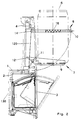
- Fig. 1 shows an ashtray, which is installed in the opening 1 of a vehicle installation part, in particular a vehicle console.
- the ashtray has an ashtray housing 2 and an ashtray pot 3.
- the exemplary embodiment is a tilting ashtray, in which the ashtray 3 can be transferred from its non-use position, shown with strong lines, to its use position, shown with dashed lines, by a pivoting movement.
- the invention can also be implemented with an ashtray with an ashtray 3 arranged like a drawer in the ashtray housing 2.
- the ashtray housing 2 which is designed as a plastic injection-molded part, has an additional housing part 4 molded thereon in one piece and of the same material, which is trough-shaped and has a vertically oriented bottom 5.
- the additional housing part 4 forms a head-side extension of the ashtray housing 2 and is used to hold a beverage can holder, which supports a beverage can 6 or a beverage bottle, a mug or the like.
- Supporting element 7 and a holding element 8 that at least partially encompasses the beverage can 6 Use position are arranged parallel to each other, includes.
- the support element 7 is designed as a lid flap 9 and the holding element 8 is designed as a ring holder 10.
- the lid flap 9 is pivotally mounted about a horizontally oriented axis 11 arranged in the lower region of the additional housing part 4 and can be closed from a position (not in use position), as shown with dashed lines, in the opening 120 of the housing part 4 Lines shown, in a horizontally aligned position (use position), as shown with solid lines, are pivoted.
- the cover flap 9 In the position of use, the cover flap 9 is held by stops 12 formed thereon, which cooperate with counter-stops 13 on the housing part 4.
- the lid flap 9 In the non-use position, the lid flap 9 is held by a locking device in the manner of an automatic tip (not shown) or a latching arrangement, likewise not shown.
- the ring holder 10 is pivotally mounted in the upper region of the additional housing part 4 about an axis 14 aligned parallel to the axis 11 in order to be able to transfer the ring holder 10 from its non-use position (shown in broken lines) to its use position (shown in solid lines).
- the articulation takes place via angle arms 15, so that the ring holder 10 can come into contact with the bottom 5 of the housing part 4 in the non-use position directly and thus in a space-saving manner.
- the lid flap 9 covers the ring holder 10 in the non-use position and lies with the front plate 16 of the ashtray 3 on a common vertical plane.
- FIG. 2 corresponds to that of FIG. 1 with respect to the main components, so that matching reference numerals have also been used for matching parts.
- a change compared to Fig. 1 is that the ashtray 3 was chosen much larger, which required a smaller size of the lid flap 9 and a displacement of the linkage for this with the same dimensioned ashtray housing 2 and housing part, as can be seen in Fig. 2.
- the ring holder 10 In order to enable the ring holder 10 to be folded into the opening 120, it can e.g. telescopic and loaded in the extended position by a spring 16.
- a relatively large ashtray 3 is also provided.
- the lid flap 9 and its articulation on the housing part 4 corresponds to the design according to FIG.
- the size and design of the ring holder 10 is unchanged from FIG. 1.
- the ring holder 10 can be accommodated here in the opening 120 in a simple manner by a guide in which 4 link grooves 17, sliding pins 18 and pivot levers 19 are involved on opposite sides of the housing part 4.
- the swivel levers 19 are articulated on one side on the housing side and on the other side on the ring holder side.
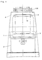
- Fig. 4 and 5 essentially show the new ashtray cup holder device in front view and top view and show that this device can also meet aesthetic requirements.
- FIG. 5 also shows the possibility of designing the ring holder 10 as being open towards the front in order to be able to accommodate it in the opening 120 in a space-saving manner.
- the ring holder 10 can therefore be shortened and end at the lines marked with 20.
- the new ashtray is intended in particular for use in openings 120 of any vehicle components.
- it is inserted in an opening 120 of a vehicle console 130 and is therefore accessible to the rear passengers of a vehicle.
- This use is of particular advantage because here, for manufacturing reasons, there is an opening widening which accommodates the additional housing part 4 anyway, which had to be veneered earlier and was usefully used by the invention.
- the new ashtray solves a need, particularly in the rear area of a vehicle, to be able to accommodate drinks without any problems and is also extremely elegant and inexpensive.
Landscapes
- Engineering & Computer Science (AREA)
- Transportation (AREA)
- Mechanical Engineering (AREA)
- Physics & Mathematics (AREA)
- Thermal Sciences (AREA)
- Passenger Equipment (AREA)
Description
- Die Erfindung bezieht sich auf einen Ascher für Fahrzeuge mit einem Aschergehäuse und einem von diesem aufgenommenen Aschertopf sowie mit einer Getränkedosenhalterung.
- Ascher für Fahrzeuge sind in den unterschiedlichsten Ausführungsformen bekanntgeworden und erfreuen sich allgemeiner Beliebtheit, und zwar auch bei Nichtrauchern, die den Aschertopf in der Regel zur Unterbringung von Kleinutensilien benutzen.
- Ein Ascher für Fahrzeuge der vorgenannten Art ist in den Unterlagen der EP-A- 0 121 119 als bekannt entnehmbar. Bei diesem bekannten Ascher ist das Aschergehäuse mit Aufnahmen zur einendigen Festlegung von Ausrüstungsteilen, zu denen auch Trinkbecherhalter gehören, ausgebildet. Die Aufnahmen sind als Stecköffnungen im Aschergehäuse oder als Zapfen am Aschergehäuse ausgebildet und geeignet, entsprechend gestaltete Endstücke der Ausrüstungsteile in auswechselbarer Anordnung aufzunehmen. Der bei diesem bekannten Ascher gezeigte Trinkbecherhalter ist nur zur Halterung konischer Trinkbecher geeignet.
- Die US-A- 4 087 126 zeigt eine Konsole in einem Fahrzeug, auf der ein plattenförmiger Trägerkörper befestigt ist. Oberhalb des Trägerkörpers erstreckt sich mit gewissem Abstand und parallel zum Trägerkörper eine Lagerplatte, die auf Tragstützen abgestützt ist. Die Lagerplatte weist mehrere Durchgangsöffnungen mit darin eingesetzten Ausrüstungsteilen, wie Ascher, Abfallbehälter und als Getränkedosenhalterungen dienende Ringkörper auf. Bei der in der US-A- 4 087 126 gezeigten Anordnung bildet der Trägerkörper ein eine Getränkedose od. dgl. abstützendes Tragelement und jeder Ringkörper ein davon beabstandetes, die Getränkedose od. dgl. umgreifendes Halteelement.
- Aufgabe der vorliegenden Erfindung ist es, einen Ascher der eingangs genannten Art weitergehend nutzbar zu machen und einen Ascher zur Verfügung zu stellen, der insbesondere zum Einsatz in Öffnungen von beliebigen Fahrzeugeinbauteilen geeignet ist und dessen Getränkedosenhalterung eine problemlose Unterbringung von Getränken ermöglichen soll. Darüber hinaus soll der Ascher elegant und kostengünstig sein.
- Zur Lösung dieser Aufgabe ist erfindungsgemäß vorgesehen, daß das Aschergehäuse aus einem Kunststoff-Spritzgußteil besteht, an dem einstückig und materialeinheitlich ein zusätzliches wannenförmig ausgebildetes Gehäuseteil mit einem in der Einbaulage senkrecht orientierten Boden angeformt ist, das zur Aufnahme der Getränkedosenhalterung bestimmt ist, welche ein eine Getränkedose od. dgl. abstützendes Tragelement und davon beabstandet ein die Getränkedose zumindest bereichsweise umgreifendes Halteelement aufweist, wobei das Tragelement und das Halteelement schwenkbeweglich in dem Gehäuseteil gelagert sind, um diese Elemente aus einer sich parallel zum Boden erstreckenden Nichtgebrauchslage in eine horizontale Gebrauchslage überführen zu können.
- Vorteilhafte Ausgestaltungen und zweckmäßige Weiterbildungen der Erfindung sind in den Unteransprüchen angegeben.
- Ausführungsbeispiele der Erfindung werden im folgenden anhand der Zeichnung näher erläutert. Es zeigen:
- Fig. 1
- den vertikalen Schnitt durch einen Ascher gemäß einer ersten Ausführungsform,
- Fig. 2
- den vertikalen Schnitt durch einen Ascher gemäß einer zweiten Ausführungsform,
- Fig. 3
- den vertikalen Schnitt durch einen Ascher gemäß einer dritten Ausführungsform,
- Fig. 4
- eine Ansicht gemäß Pfeilrichtung X nach Fig. 1 und
- Fig. 5
- einen Schnitt etwa folgend der Linie V-V in Fig. 1.
- Fig. 1 zeigt einen Ascher, der in die Öffnung 1 eines Fahrzeugeinbauteils, in Sonderheit einer Fahrzeugkonsole eingebaut ist. Der Ascher weist ein Aschergehäuse 2 und einen Aschertopf 3 auf. Beim Ausführungsbeispiel handelt es sich um einen Kippascher, bei dem der Aschertopf 3 durch eine Schenkbewegung aus seiner mit starken Linien dargestellten Nichtgebrauchslage in seine mit gestrichelten Linien dargestellten Gebrauchslage überführt werden kann. Die Erfindung ist aber auch bei einem Ascher mit schubladenartig im Aschergehäuse 2 angeordneten Aschertopf 3 realisierbar.
- Das Aschergehäuse 2, das als Kunststoff-Spritzgußteil ausgebildet ist weist ein daran einstückig und materialeinheitlich angeformtes zusätzliches Gehäuseteil 4 auf, das wannenförmig ausgebildet ist und einen senkrecht orientierten Boden 5 besitzt. Das zusätzliche Gehäuseteil 4 bildet eine kopfseitige Verlängerung des Aschergehäuses 2 und dient zur Aufnahme einer Getränkedosenhalterung, die ein eine Getränkedose 6 oder eine Getränkeflasche, einen Becher od. dgl. abstützendes Tragelement 7 und ein die Getränkedose 6 zumindest bereichsweise umgreifendes Halteelement 8, die in der Gebrauchslage parallel zueinander angeordnet sind, umfaßt. Das Tragelement 7 ist als Deckelklappe 9 und das Halteelement 8 ist als Ringhalter 10 ausgebildet.
- Die Deckelklappe 9 ist um eine waagerecht ausgerichtete, im unteren Bereich des zusätzlichen Gehäuseteils 4 angeordneten Achse 11 schwenkbar gelagert und kann aus einer die Öffnung 120 des Gehäuseteils 4 verschließenden Stellung (Nichtgebrauchslage), wie mit gestrichelten Linien dargestellt, in eine waagerecht ausgerichtete Stellung (Gebrauchslage), wie mit stark ausgezogenen Linien dargestellt, verschwenkt werden. In der Gebrauchslage wird die Deckelklappe 9 durch daran angeformte Anschläge 12, die mit Gegenanschlägen 13 am Gehäuseteil 4 zusammenwirken, gehalten. In der Nichtgebrauchslage erfolgt die Halterung der Deckelklappe 9 durch eine Verriegelungsvorrichtung nach Art einer Tip-Automatik (nicht gezeigt) oder einer ebenfalls nicht näher dargestellten Rastausbildung.
- Der Ringhalter 10 ist im oberen Bereich des zusätzlichen Gehäuseteils 4 um eine parallel zur Achse 11 ausgerichtete Achse 14 schwenkbar gelagert, um den Ringhalter 10 aus seiner Nichtgebrauchslage (gestrichelt dargestellt) in seine Gebrauchslage (mit ausgezogenen Linien dargestellt) überführen zu können. Die Anlenkung erfolgt über Winkelarme 15, damit der Ringhalter 10 in der Nichtgebrauchslage unmittelbar und damit platzsparend am Boden 5 des Gehäuseteils 4 zur Anlage kommen kann. Die Deckelklappe 9 deckt den Ringhalter 10 in der Nichtgebrauchslage ab und liegt im übrigen mit der Frontplatte 16 des Aschertopfs 3 auf einer gemeinsamen senkrechten Ebene.
- Das Ausführungsbeispiel nach Fig. 2 entspricht hinsichtlich der Hauptbauelemente dem nach Fig. 1, so daß für übereinstimmende Teile auch übereinstimmende Bezugszeichen verwendet worden sind. Eine Veränderung gegenüber Fig. 1 besteht darin, daß der Aschertopf 3 wesentlich größer gewählt wurde, was bei gleich bemessenem Aschergehäuse 2 und Gehäuseteil 4 eine Verkleinerung der Deckelklappe 9 und einer Verlagerung der Anlenkung für diese verlangte, wie dies in Fig. 2 verdeutlich ist. Um ein Einklappen des Ringhalters 10 in die Öffnung 120 zu ermöglichen, kann dieser z.B. teleskopierbar und in der ausgefahrenen Stellung durch eine Feder 16 belastet sein.
- Beim Ausführungsbeispiel nach Fig. 3, bei dem für übereinstimmende Teile wiederum auch übereinstimmende Bezugszeichen eingesetzt sind, ist ebenfalls ein relativ großer Aschertopf 3 vorgesehen. Die Deckelklappe 9 und deren Anlenkung am Gehäuseteil 4 entspricht der Ausbildung nach Fig. 2. Die Ausbildung und Anlenkung ermöglicht durch eine dadurch geschaffene Griffmulde 17 eine leichte Bedienbarkeit des Aschertopfs 3.
- Die Größe und Gestaltung des Ringhalters 10 ist gegenüber Fig. 1 unverändert. Der Ringhalter 10 kann hier in der Öffnung 120 in einfacher Weise durch eine Führung untergebracht werden, bei der an gegenüberliegenden Seiten des Gehäuseteils 4 Kulissennuten 17, darin gleitende Zapfen 18 und Schwenkhebel 19 beteiligt sind. Die Schwenkhebel 19 sind einendig gehäuseseitig und anderendig ringhalterseitig angelenkt.
- Fig. 4 und 5 zeigen im wesentlichen die neue Ascher-Getränkehalter-Einrichtung in Vorderansicht und Draufsicht und lassen erkennen, daß diese Einrichtung auch ästhetischen Ansprüchen zu genügen vermag.
- Fig. 5 zeigt zudem die Möglichkeit den Ringhalter 10 als nach vorne offen auszubilden, um ihn platzsparender in der Öffnung 120 unterbringen zu können. Der Ringhalter 10 kann also verkürzt sein und an den mit 20 gekennzeichneten Linien enden.
- Der neue Ascher ist insbesondere zum Einsatz in Öffnungen 120 von beliebigen Fahrzeugeinbauteilen bestimmt. In den dargestellten Ausführungsbeispielen ist er in einer Öffnung 120 einer Fahrzeugkonsole 130 eingesetzt und damit von den Fondinsassen eines Fahrzeugs zugänglich. Dieser Einsatz ist von besonderem Vorteil, weil hier aus fertigungstechnischen Gründen ohnehin eine das zusätzliche Gehäuseteil 4 aufnehmende Öffnungsenweiterung vorhanden ist, die früher verblendet werden mußte und durch die Erfindung in sinnvoller Weise nutzbar gemacht wurde. Darüber hinaus wird durch den neuen Ascher ein vornehmlich im Fondbereich eines Fahrzeugs vorhandenes Bedürfnis, Getränke problemlos unterbringen zu können gelöst und zudem noch äußerst elegant und kostengünstig.
Claims (5)
- Ascher für Fahrzeuge mit einem Aschergehäuse (2) und einem von diesem aufgenommenen Aschertopf (3) sowie mit einer Getränkedosenhalterung, dadurch gekennzeichnet, daß das Aschergehäuse (2) aus einem Kunststoff-Spritzgußteil besteht, an dem einstückig und materialeinheitlich ein zusätzliches wannenförmig ausgebildetes Gehäuseteil (4) mit einem in der Einbaulage senkrecht orientierten Boden (5) angeformt ist, das zur Aufnahme der Getränkedosenhalterung bestimmt ist, welche ein eine Getränkedose (6) od. dgl. abstützendes Tragelement (7) und davon beabstandet ein die Getränkedose (6) zumindest bereichsweise umgreifendes Halteelement (8) aufweist, wobei das Tragelement (7) und das Halteelement (8) schwenkbeweglich in dem Gehäuseteil (4) gelagert sind, um diese Elemente (7, 8) aus einer sich parallel zum Boden (5) erstreckenden Nichtgebrauchslage in eine horizontale Gebrauchslage überführen zu können.
- Ascher nach Anspruch 1, dadurch gekennzeichnet, daß das Halteelement (8) um eine horizontal ausgerichtete, im oberen Bereich des Gehäuseteils (4) angeordnete Achse (14) schwenkbar und in der Nichtgebrauchslage dem Boden (5) unmittelbar benachbart ist, während das Tragelement (7) um eine horizontal ausgerichtete, im unteren Bereich des Gehäuseteils (4) angeordnete Achse (11) schwenkbar ist, in der Nichtgebrauchslage am Halteelement (8) anliegt und als Deckelklappe (9) ausgebildet ist.
- Ascher nach Anspruch 1 oder 2, dadurch gekennzeichnet, daß das zusätzliche Gehäuseteil (4) das eigentliche Aschergehäuse (2) seitlich oder nach unter oder nach oben überragt.
- Ascher nach wenigstens einem der Ansprüche 1 bis 3, dadurch gekennzeichnet, daß Mittel vorgesehen sind, um das Tragelement (7) wie auch das Halteelement (8) sowohl in der Gebrauchslage als auch in der Nichtgebrauchslage zu arretieren.
- Ascher nach wenigstens einem der Ansprüche 1 bis 4, dadurch gekennzeichnet, daß das Halteelement (8) als ggf. vorderseitig offener Ringhalter (10) ausgebildet ist.
Applications Claiming Priority (2)
| Application Number | Priority Date | Filing Date | Title |
|---|---|---|---|
| DE4315584A DE4315584A1 (de) | 1993-05-11 | 1993-05-11 | Ascher für Fahrzeuge |
| DE4315584 | 1993-05-11 |
Publications (2)
| Publication Number | Publication Date |
|---|---|
| EP0624490A1 EP0624490A1 (de) | 1994-11-17 |
| EP0624490B1 true EP0624490B1 (de) | 1996-09-11 |
Family
ID=6487732
Family Applications (1)
| Application Number | Title | Priority Date | Filing Date |
|---|---|---|---|
| EP94106942A Expired - Lifetime EP0624490B1 (de) | 1993-05-11 | 1994-05-04 | Ascher für Fahrzeuge |
Country Status (4)
| Country | Link |
|---|---|
| US (1) | US5533772A (de) |
| EP (1) | EP0624490B1 (de) |
| DE (2) | DE4315584A1 (de) |
| ES (1) | ES2094586T3 (de) |
Families Citing this family (20)
| Publication number | Priority date | Publication date | Assignee | Title |
|---|---|---|---|---|
| DE19543925C1 (de) * | 1995-11-24 | 1997-02-20 | Daimler Benz Ag | Multifunktionales Servicefach für Fahrzeuge |
| US5680974A (en) * | 1996-03-01 | 1997-10-28 | Atlantic Automotive Components, Inc. | Articulating cupholder assembly |
| FR2747969B1 (fr) * | 1996-04-26 | 1998-06-12 | Peugeot | Cendrier modulable pour vehicule automobile |
| DE29618336U1 (de) * | 1996-10-22 | 1997-01-23 | Dr.Ing.H.C. F. Porsche Ag, 70435 Stuttgart | Behältnis zur Aufnahme von Gegenständen in einem Kraftfahrzeug |
| US6290229B1 (en) | 1999-12-20 | 2001-09-18 | The Miccosukee Tribe Of Indians Of Florida | Customer support device for a gaming machine |
| DE10015197A1 (de) * | 2000-03-27 | 2001-10-04 | Fischer Artur Werke Gmbh | Halterung für einen Getränkebehälter |
| DE10016463A1 (de) * | 2000-04-01 | 2001-10-11 | Fischer Artur Werke Gmbh | Halter für einen Getränkebehälter |
| US6629716B2 (en) * | 2001-06-27 | 2003-10-07 | Toyoda Gosei Co., Ltd. | Structure for holding functional device |
| DE10155798A1 (de) * | 2001-11-14 | 2003-05-22 | Fischer Automotive Sys Gmbh | Einbaukombination für ein Fortbewegungsmittel |
| JP2003276515A (ja) * | 2002-03-22 | 2003-10-02 | Nifco Inc | スライド及び回動運動のガイド機構、該ガイド機構を用いた蓋体の開閉機構、及び該開閉機構を用いた車載用内装品 |
| US6866265B2 (en) * | 2002-07-19 | 2005-03-15 | Sierra Design Group | Movable gaming machine tray |
| US7077456B2 (en) * | 2004-03-11 | 2006-07-18 | Lear Corporation | Automotive interior trim assembly and pad insertion |
| US20060012205A1 (en) * | 2004-07-15 | 2006-01-19 | Bogdan Radu | Automotive storage compartment and method for making the same |
| US7032954B2 (en) * | 2004-07-15 | 2006-04-25 | Lear Corporation | Automotive ashtray and method for making the same |
| US7086683B2 (en) * | 2004-07-15 | 2006-08-08 | Lear Corporation | Sunvisor attachment for vehicles and method for making the same |
| US7017968B1 (en) | 2004-09-29 | 2006-03-28 | Lear Corporation | Automotive ashtray having an electroluminescent lamp and method of making the same |
| US8141759B2 (en) * | 2008-01-08 | 2012-03-27 | Toyota Motor Engineering & Manufacturing North America, Inc. | Container assembly for a motor vehicle |
| NL2005150C2 (nl) * | 2010-07-24 | 2012-01-25 | Daf Trucks Nv | Bekerhouder voor een truck. |
| US8573668B2 (en) * | 2011-11-21 | 2013-11-05 | Ford Global Technologies, Llc | Retracting storage tray system with locking trunnion |
| US8540300B1 (en) * | 2012-03-30 | 2013-09-24 | Toyota Motor Engineering & Manufacturing North America, Inc. | Coin box |
Family Cites Families (15)
| Publication number | Priority date | Publication date | Assignee | Title |
|---|---|---|---|---|
| GB276147A (en) * | 1926-08-24 | 1927-08-25 | Carl Louis Breeden | An improved smoker's ash receptacle particularly suitable for use upon an automobile |
| US3186671A (en) * | 1963-07-12 | 1965-06-01 | Henderson B Standley | Receptacle holder |
| US3356409A (en) * | 1965-09-09 | 1967-12-05 | Ford Motor Co | Sliding console |
| US4087126A (en) * | 1976-11-15 | 1978-05-02 | Luce Industries, Inc. | Console for van-type vehicles |
| DE2834955B2 (de) * | 1978-08-10 | 1981-04-09 | Gebr. Happich Gmbh, 5600 Wuppertal | Garnitur für Fahrzeuge |
| US4286742A (en) * | 1980-02-29 | 1981-09-01 | Bernard Pellegrino | Cup holder |
| DE3310658A1 (de) * | 1983-03-24 | 1984-09-27 | Gebr. Happich Gmbh, 5600 Wuppertal | Ascher, insbesondere fuer fahrzeuge |
| US4535923A (en) * | 1983-03-25 | 1985-08-20 | Manke James E | Automobile beverage holding device |
| ATE43128T1 (de) * | 1983-05-27 | 1989-06-15 | Johnson Filtration Systems | Enthaertung mittels kalk und querstrommikrofiltration. |
| US4953772A (en) * | 1986-11-17 | 1990-09-04 | Greg Phifer | Ashtray replacement drink holder |
| US5167392A (en) * | 1990-12-26 | 1992-12-01 | Enginuity Inc. | Collapsible beverage container receptacle with pivotally adjustable arms |
| JPH0672228A (ja) * | 1992-08-26 | 1994-03-15 | Nissan Motor Co Ltd | 乗物用カップホルダ装置 |
| JP2927317B2 (ja) * | 1992-08-26 | 1999-07-28 | 日産自動車株式会社 | 乗物用カップホルダ装置 |
| JPH0672227A (ja) * | 1992-08-26 | 1994-03-15 | Nissan Motor Co Ltd | 乗物用カップホルダ装置 |
| US5423508A (en) * | 1993-10-12 | 1995-06-13 | Itc, Incorporated | Foldable support for beverage container |
-
1993
- 1993-05-11 DE DE4315584A patent/DE4315584A1/de not_active Withdrawn
-
1994
- 1994-05-04 ES ES94106942T patent/ES2094586T3/es not_active Expired - Lifetime
- 1994-05-04 EP EP94106942A patent/EP0624490B1/de not_active Expired - Lifetime
- 1994-05-04 DE DE59400624T patent/DE59400624D1/de not_active Expired - Fee Related
- 1994-05-06 US US08/239,398 patent/US5533772A/en not_active Expired - Fee Related
Also Published As
| Publication number | Publication date |
|---|---|
| ES2094586T3 (es) | 1997-01-16 |
| US5533772A (en) | 1996-07-09 |
| DE4315584A1 (de) | 1995-01-12 |
| EP0624490A1 (de) | 1994-11-17 |
| DE59400624D1 (de) | 1996-10-17 |
Similar Documents
| Publication | Publication Date | Title |
|---|---|---|
| EP0667258B1 (de) | Vorrichtung zum Halten von Getränkebehältern, Trinkgefässen oder dgl. | |
| EP0624490A1 (de) | Ascher für Fahrzeuge | |
| DE69307087T2 (de) | Ausschwenkbarer Becherhalter für Armlehne | |
| EP0764558B1 (de) | Einbau-Vorrichtung insbesondere für Fahrzeuge | |
| WO2001060657A1 (de) | Halterung für getränkebehälter | |
| EP1312501B1 (de) | Anordnung von einem Behältnis und einem Becherhalter für ein Fortbewegungsmittel | |
| DE4327869C1 (de) | Ablagefach mit Schließklappe und an dieser angeordnetem Klapptisch | |
| DE19616774C2 (de) | Trinkgefäßhalter für Fahrzeuge | |
| EP1181169B1 (de) | Halter für einen getränkebehälter | |
| EP1227000A2 (de) | Halter für eine Flasche zum Einbau in einen Kraftwagen | |
| DE4302948A1 (de) | Handschuhfach für ein Kraftfahrzeug | |
| DE3534098C2 (de) | ||
| DE19652715C2 (de) | Haltevorrichtung für das Bedienelement eines Telefons oder Mobiltelefons | |
| DE60204774T2 (de) | Konsolenkasten Anordnung | |
| DE4228848C1 (de) | Haltevorrichtung für Getränkeflaschen an einem Fahrzeugsitz mit Armlehne | |
| EP0842815B1 (de) | Aufnahmevorrichtung für Gegenstände in Fahrzeugen | |
| DE20204882U1 (de) | Halter für einen Getränkebehälter | |
| DE19543925C1 (de) | Multifunktionales Servicefach für Fahrzeuge | |
| DE10138292B4 (de) | Konsole mit Getränkehaltern mit einem Schubladenprinzip | |
| EP0779178B1 (de) | Vorrichtung in der Form einer Kassette zur Aufnahme/Halterung von Behältnissen | |
| DE10245740B4 (de) | Haltevorrichtung für Getränkebehälter im Staufach eines Fahrzeugs | |
| DE102008052894B4 (de) | Trinkgefäßhalter | |
| DE202006015245U1 (de) | Verriegelungsmechanik und Anordnung mit einer Verriegelungsmechanik | |
| DE19524419C1 (de) | Becherhalter zum Aufnehmen von wenigstens einem Trinkbehältnis | |
| DE7725026U1 (de) | Ascher, insbesondere fuer kraftfahrzeuge |
Legal Events
| Date | Code | Title | Description |
|---|---|---|---|
| PUAI | Public reference made under article 153(3) epc to a published international application that has entered the european phase |
Free format text: ORIGINAL CODE: 0009012 |
|
| 17P | Request for examination filed |
Effective date: 19940819 |
|
| AK | Designated contracting states |
Kind code of ref document: A1 Designated state(s): BE DE ES FR GB IT LU NL |
|
| 17Q | First examination report despatched |
Effective date: 19951011 |
|
| GRAG | Despatch of communication of intention to grant |
Free format text: ORIGINAL CODE: EPIDOS AGRA |
|
| GRAH | Despatch of communication of intention to grant a patent |
Free format text: ORIGINAL CODE: EPIDOS IGRA |
|
| GRAH | Despatch of communication of intention to grant a patent |
Free format text: ORIGINAL CODE: EPIDOS IGRA |
|
| GRAA | (expected) grant |
Free format text: ORIGINAL CODE: 0009210 |
|
| ITPR | It: changes in ownership of a european patent |
Owner name: C.O N.ME EPO REG.92;BECKER GROUP EUROPE GMBK |
|
| AK | Designated contracting states |
Kind code of ref document: B1 Designated state(s): BE DE ES FR GB IT LU NL |
|
| REF | Corresponds to: |
Ref document number: 59400624 Country of ref document: DE Date of ref document: 19961017 |
|
| RAP2 | Party data changed (patent owner data changed or rights of a patent transferred) |
Owner name: BECKER GROUP EUROPE GMBH |
|
| ITF | It: translation for a ep patent filed | ||
| ET | Fr: translation filed | ||
| NLT2 | Nl: modifications (of names), taken from the european patent patent bulletin |
Owner name: BECKER GROUP EUROPE GMBH |
|
| GBT | Gb: translation of ep patent filed (gb section 77(6)(a)/1977) |
Effective date: 19961209 |
|
| REG | Reference to a national code |
Ref country code: ES Ref legal event code: FG2A Ref document number: 2094586 Country of ref document: ES Kind code of ref document: T3 |
|
| REG | Reference to a national code |
Ref country code: FR Ref legal event code: CD |
|
| PLBE | No opposition filed within time limit |
Free format text: ORIGINAL CODE: 0009261 |
|
| STAA | Information on the status of an ep patent application or granted ep patent |
Free format text: STATUS: NO OPPOSITION FILED WITHIN TIME LIMIT |
|
| 26N | No opposition filed | ||
| REG | Reference to a national code |
Ref country code: GB Ref legal event code: IF02 |
|
| PGFP | Annual fee paid to national office [announced via postgrant information from national office to epo] |
Ref country code: FR Payment date: 20030411 Year of fee payment: 10 |
|
| PGFP | Annual fee paid to national office [announced via postgrant information from national office to epo] |
Ref country code: GB Payment date: 20030417 Year of fee payment: 10 |
|
| PGFP | Annual fee paid to national office [announced via postgrant information from national office to epo] |
Ref country code: NL Payment date: 20030425 Year of fee payment: 10 |
|
| PGFP | Annual fee paid to national office [announced via postgrant information from national office to epo] |
Ref country code: LU Payment date: 20030429 Year of fee payment: 10 |
|
| PGFP | Annual fee paid to national office [announced via postgrant information from national office to epo] |
Ref country code: ES Payment date: 20030506 Year of fee payment: 10 |
|
| PGFP | Annual fee paid to national office [announced via postgrant information from national office to epo] |
Ref country code: BE Payment date: 20030508 Year of fee payment: 10 |
|
| PGFP | Annual fee paid to national office [announced via postgrant information from national office to epo] |
Ref country code: DE Payment date: 20030531 Year of fee payment: 10 |
|
| PG25 | Lapsed in a contracting state [announced via postgrant information from national office to epo] |
Ref country code: LU Free format text: LAPSE BECAUSE OF NON-PAYMENT OF DUE FEES Effective date: 20040504 Ref country code: GB Free format text: LAPSE BECAUSE OF NON-PAYMENT OF DUE FEES Effective date: 20040504 |
|
| PG25 | Lapsed in a contracting state [announced via postgrant information from national office to epo] |
Ref country code: ES Free format text: LAPSE BECAUSE OF NON-PAYMENT OF DUE FEES Effective date: 20040505 |
|
| PG25 | Lapsed in a contracting state [announced via postgrant information from national office to epo] |
Ref country code: BE Free format text: LAPSE BECAUSE OF NON-PAYMENT OF DUE FEES Effective date: 20040531 |
|
| BERE | Be: lapsed |
Owner name: *BECKER GROUP EUROPE G.M.B.H. Effective date: 20040531 |
|
| PG25 | Lapsed in a contracting state [announced via postgrant information from national office to epo] |
Ref country code: NL Free format text: LAPSE BECAUSE OF NON-PAYMENT OF DUE FEES Effective date: 20041201 Ref country code: DE Free format text: LAPSE BECAUSE OF NON-PAYMENT OF DUE FEES Effective date: 20041201 |
|
| GBPC | Gb: european patent ceased through non-payment of renewal fee |
Effective date: 20040504 |
|
| PG25 | Lapsed in a contracting state [announced via postgrant information from national office to epo] |
Ref country code: FR Free format text: LAPSE BECAUSE OF NON-PAYMENT OF DUE FEES Effective date: 20050131 |
|
| NLV4 | Nl: lapsed or anulled due to non-payment of the annual fee |
Effective date: 20041201 |
|
| REG | Reference to a national code |
Ref country code: FR Ref legal event code: ST |
|
| PG25 | Lapsed in a contracting state [announced via postgrant information from national office to epo] |
Ref country code: IT Free format text: LAPSE BECAUSE OF NON-PAYMENT OF DUE FEES Effective date: 20050504 |
|
| REG | Reference to a national code |
Ref country code: ES Ref legal event code: FD2A Effective date: 20040505 |