EP0624429B1 - Method for the controlled removal of chips in boring mills and boring mills produced with this method - Google Patents
Method for the controlled removal of chips in boring mills and boring mills produced with this method Download PDFInfo
- Publication number
- EP0624429B1 EP0624429B1 EP94106898A EP94106898A EP0624429B1 EP 0624429 B1 EP0624429 B1 EP 0624429B1 EP 94106898 A EP94106898 A EP 94106898A EP 94106898 A EP94106898 A EP 94106898A EP 0624429 B1 EP0624429 B1 EP 0624429B1
- Authority
- EP
- European Patent Office
- Prior art keywords
- fluid
- chips
- chuck
- jet
- duct
- Prior art date
- Legal status (The legal status is an assumption and is not a legal conclusion. Google has not performed a legal analysis and makes no representation as to the accuracy of the status listed.)
- Expired - Lifetime
Links
Images



Classifications
-
- B—PERFORMING OPERATIONS; TRANSPORTING
- B23—MACHINE TOOLS; METAL-WORKING NOT OTHERWISE PROVIDED FOR
- B23Q—DETAILS, COMPONENTS, OR ACCESSORIES FOR MACHINE TOOLS, e.g. ARRANGEMENTS FOR COPYING OR CONTROLLING; MACHINE TOOLS IN GENERAL CHARACTERISED BY THE CONSTRUCTION OF PARTICULAR DETAILS OR COMPONENTS; COMBINATIONS OR ASSOCIATIONS OF METAL-WORKING MACHINES, NOT DIRECTED TO A PARTICULAR RESULT
- B23Q11/00—Accessories fitted to machine tools for keeping tools or parts of the machine in good working condition or for cooling work; Safety devices specially combined with or arranged in, or specially adapted for use in connection with, machine tools
- B23Q11/0042—Devices for removing chips
- B23Q11/005—Devices for removing chips by blowing
-
- Y—GENERAL TAGGING OF NEW TECHNOLOGICAL DEVELOPMENTS; GENERAL TAGGING OF CROSS-SECTIONAL TECHNOLOGIES SPANNING OVER SEVERAL SECTIONS OF THE IPC; TECHNICAL SUBJECTS COVERED BY FORMER USPC CROSS-REFERENCE ART COLLECTIONS [XRACs] AND DIGESTS
- Y02—TECHNOLOGIES OR APPLICATIONS FOR MITIGATION OR ADAPTATION AGAINST CLIMATE CHANGE
- Y02P—CLIMATE CHANGE MITIGATION TECHNOLOGIES IN THE PRODUCTION OR PROCESSING OF GOODS
- Y02P70/00—Climate change mitigation technologies in the production process for final industrial or consumer products
- Y02P70/10—Greenhouse gas [GHG] capture, material saving, heat recovery or other energy efficient measures, e.g. motor control, characterised by manufacturing processes, e.g. for rolling metal or metal working
-
- Y—GENERAL TAGGING OF NEW TECHNOLOGICAL DEVELOPMENTS; GENERAL TAGGING OF CROSS-SECTIONAL TECHNOLOGIES SPANNING OVER SEVERAL SECTIONS OF THE IPC; TECHNICAL SUBJECTS COVERED BY FORMER USPC CROSS-REFERENCE ART COLLECTIONS [XRACs] AND DIGESTS
- Y10—TECHNICAL SUBJECTS COVERED BY FORMER USPC
- Y10S—TECHNICAL SUBJECTS COVERED BY FORMER USPC CROSS-REFERENCE ART COLLECTIONS [XRACs] AND DIGESTS
- Y10S82/00—Turning
- Y10S82/901—Chip removal
-
- Y—GENERAL TAGGING OF NEW TECHNOLOGICAL DEVELOPMENTS; GENERAL TAGGING OF CROSS-SECTIONAL TECHNOLOGIES SPANNING OVER SEVERAL SECTIONS OF THE IPC; TECHNICAL SUBJECTS COVERED BY FORMER USPC CROSS-REFERENCE ART COLLECTIONS [XRACs] AND DIGESTS
- Y10—TECHNICAL SUBJECTS COVERED BY FORMER USPC
- Y10T—TECHNICAL SUBJECTS COVERED BY FORMER US CLASSIFICATION
- Y10T408/00—Cutting by use of rotating axially moving tool
- Y10T408/44—Cutting by use of rotating axially moving tool with means to apply transient, fluent medium to work or product
- Y10T408/45—Cutting by use of rotating axially moving tool with means to apply transient, fluent medium to work or product including Tool with duct
- Y10T408/455—Conducting channel extending to end of Tool
-
- Y—GENERAL TAGGING OF NEW TECHNOLOGICAL DEVELOPMENTS; GENERAL TAGGING OF CROSS-SECTIONAL TECHNOLOGIES SPANNING OVER SEVERAL SECTIONS OF THE IPC; TECHNICAL SUBJECTS COVERED BY FORMER USPC CROSS-REFERENCE ART COLLECTIONS [XRACs] AND DIGESTS
- Y10—TECHNICAL SUBJECTS COVERED BY FORMER USPC
- Y10T—TECHNICAL SUBJECTS COVERED BY FORMER US CLASSIFICATION
- Y10T82/00—Turning
- Y10T82/10—Process of turning
Definitions
- the present invention is intended to resolve the problem of the removal of chips in boring mills, in order to prevent the chips from remaining in the working region of the tool and causing problems concerning the quality of machining of the piece, the life of the tool and the automation of the working cycle of the boring mill.
- JP-A-61-203246 describes a method for the controlled removal of chips in a boring mill of the type comprising a table for holding a workpiece, a cutting tool (315) for cutting the workpiece, means disposed above said workpiece for feeding a cutting fluid to said workpiece during the cutting operations, and means for collecting said cutting fluid, the method comprising the steps of forming a vertical duct through said table open at the top end next to the said workpiece held by table, and open at its bottom end over said cutting fluid collecting means, directing at the cutting zone cutting fluid to lubricate and cool the tool, removing by filtration said chips from said cutting fluid, and recycling said filtered cutting fluid.
- JP-A-61-203246 also describes a boring mill comprising a table for holding a workpiece, holder means for a cutting tool for cutting said workpiece, a vertical duct in said table which is open at the top end next to the workpiece held by the table and which is open at the opposite, bottom end over cutting fluid collecting means, cutting fluid supplying means for directing at the cutting zone cutting fluid to lubricate and cool the tool, means for removing by filtration said chips from said collected cutting fluid, and pump means for recycling said filtered cutting fluid.
- the invention resolves this problem by the method as claimed in claim 1 and by a boring mill as claimed in claim 9.
- the chuck of the boring mill and the corresponding operating bar, together with the moving unit of the cylinder and piston assembly which provides the axial movement of the bar, are made with an axially hollow shape, so that they form a vertical duct which is open at the top next to the workpiece mounted in the chuck, and with is open at the bottom above a conveyor with a filter and a unit for collecting and pumping the cutting fluid.
- the chips which are formed during the machining of the piece mounted in the chuck are transported and removed downwards, through the said duct, by at least one jet of fluid at high pressure, for example of the order of at least 130-200 bar, which has a location and direction such that it strikes the chip after its formation without interfering with the normal jet of fluid at low pressure which is applied uniformly to the tool.
- the jet or jets of fluid at high pressure which remove the chips consist of the same cutting fluid as that which is directed against the tool at low pressure.
- the chips and cutting fluid leaving the lower end of the said vertical duct are collected by the conveyor and filter assembly which removes the chips to a collection area and which filters and collects the fluid which is supplied by two different sets of pumps to the ducts formed in the toolholder and from which the jets at high and low pressure emerge for the various purposes mentioned above.
- the reference 1 indicates the arbor of the boring mill, which is fixed by the stator part 101 to a base structure 2.
- the chuck 3 is mounted on top of the rotating part of the arbor and grips the workpiece with its jaws 103.
- the said rotating part of the arbor With the part which projects downwards from the stator 101, the said rotating part of the arbor carries the toothed pulley 4 connected with a belt to a driving motor which is not shown, and also carries and is keyed to the body of a cylinder and piston assembly 5 operating by fluid pressure, with an associated rotating distributor 6, for the supply of the assembly 5 from fixed points, which in turn is fixed to a fixed point 54 of the base 2 or of other fixed parts.
- the piston of the cylinder and piston assembly 5 is axially hollow and is fixed at the lower end of the vertical bar 7 (Fig. 2) which is also axially hollow (see below) and is fixed by its upper end to the mechanism 203 for opening and closing the jaws 103 of the chuck 3.
- the upper end of the bar 7 projects beyond the previously mentioned mechanism 203 and has inserted in it telescopically, with sufficient clearance, a funnel 8 fixed with clamps 9 in the radial cavities of the body of the chuck 3.
- the upper shape of the funnel may vary according to the shape of the workpiece, and the funnel may advantageously be associated with reference pieces 10 on which the workpiece P is initially positioned so that it is correctly placed before being gripped by the jaws 103.
- the funnel 8 has the function of extending, and bringing as close as possible to the workpiece, the vertical duct C which passes through the bar 7 and the corresponding operating cylinder 5, and which is designed for the collection and removal of the chips.
- the bar 7 is formed by a hollow rod 107 fixed by its lower end to the piston of the cylinder and piston assembly 5 (see below) and fixed by its upper end to a tube 207 on which an extension tube 307 is screwed, the flange 11 integral with the chuck opening and closing mechanism 203 being clamped between the two tubes.
- the tube 307 has externally fitted seals 12 with which it slides with a lateral seal through the part 303 of the body of the chuck. It is to be understood that the bar 7 may be made with a number of parts different from that described, for example with two parts or with only one part.
- the device of a known type 13 which collects the chips and the cutting fluid from the machining of the piece, which removes the chips to a collection point, and which filters the fluid which is then taken up by suitable pumps (see below) and supplied to the tool-holder, is disposed below the previously mentioned vertical duct C.
- 14 indicates the support which is fixed to the orthogonal movement slide of the boring mill and which is designed to hold securely, with a rapid and known method of attachment, the mounting or shank 115 of the toolholder 15, provided with a flange 215 which bears frontally on the underside of the said body.
- the flange 215 is normally provided with an offset cavity open at the top for interaction with a reference pin 16 carried by the support 14, to ensure the centring and consequent connection between the upper end of a duct 17 formed in the toolholder 15 and the lower end of a duct 18 which is formed in the support 14 and abuts against a duct leading from a low-pressure pump 19 which draws the cutting fluid from the reservoir of the device 13 (Fig. 1).
- the lower end of the duct 17 opens in the intermediate part of the body of the toolholder 15, of an inclined plane, and supplies the cutting fluid to the tool 315, with known characteristics of pressure and flow.
- the pressure of the fluid leaving the duct 17 is approximately of the order of 30 bar.
- the cutting fluid is also drawn from the reservoir of the device 13 by a pump 20 capable of operating at a very high pressure, for example of the order of at least 130-200 bar, with a flow rate of the order of approximately 30 litres per minute, and the fluid at high pressure is sent through a duct 21 into a duct 22 formed in the support 14.
- a pump 20 capable of operating at a very high pressure, for example of the order of at least 130-200 bar, with a flow rate of the order of approximately 30 litres per minute, and the fluid at high pressure is sent through a duct 21 into a duct 22 formed in the support 14.
- the duct 22 opens on to the lower face of the supprt 14 and abuts on and is connected to a duct 23 which passes through the flange 215 and which emerges from the latter with a location and direction such that a jet of fluid at high pressure is supplied and passes from the top to the bottom of the workpiece P, runs in the clearance between the duct C and the toolholder 15, and does not interfere with the jet of fluid at low pressure which is directed against the tool and strikes the chip after its formation, impelling it towards the collection and removal device 13.
- An adjustable nozzle 24 may be mounted at the lower end of the duct 23.
- Figure 4 shows that the jet of fluid at high pressure which emerges from the duct 23 may be located at the point, easily deducible from practical tests, at which, according to the direction of rotation F of the piece P and to the shape of the tool 315 and/or any other parameters, the chips T tend to accumulate, so that these chips are rapidly struck by the said jet of fluid and compelled to flow downwards.
- the location of the jet of fluid at high pressure above the tool permits action on those chips which initially tend to rise rather than to fall.
- the location of the jet of fluid at high pressure may be different from that shown, and that a number of jets at high pressure, suitably spaced apart and distributed in the round angle, may be provided, the whole in a way which may be understood and easily applied by engineers working in this field.
- the jet of fluid at high pressure may be directed downwards, parallel to the axis of the arbor or suitably inclined, so that a true vortex is formed in the duct C.
- the duct 21 may be made to communicate with ducts 123 formed in the flange 215 and in the body of the toolholder 15 and discharging into the lower end of this body, below the tool 315, so that at least one jet of fluid at high pressure, useful for the removal of the chips, is discharged from the lower part of this body, possibly through an adjustable nozzle 124.
- a combined supply of jets of fluid at high pressure is provided from both duct 23 and duct 123, and consequently from both the upper and the lower part of the toolholder.
- the advantages derived from the solution described may be summarised as follows. Because of their weight, the chips have a natural tendency to fall. The jet or jets of fluid at high pressure promote the promote the natural removal of the chips, so that no accumulations of chips occurs in the working area of the tool as occurs in the known art, with advantages both in the quality of machining and in the life of the tool. It has been found from long-term tests that the like of the tool is almost doubled by comparison to that of the tools used in boring mills of known type.
- the chuck of the boring mill remains clean and in the best condition to be served by automatic systems for the supply and removal of the workpieces and the finished pieces.
- the drive pulley 4 and the pulley 25 connected to the tachometer unit of a known type, designed for the monitoring of the rotation speed and angular position of the arbor are keyed to the lower part of the rotating part 201 of the arbor.
- the pulley 25 is fixed between a pair of flanges 26-126, the latter of which is fixed to the rotating part 201, and the part 107 of the hollow bar 7 projects axially from this assembly.
- the body 105 of the cylinder and piston assembly 5 provided at its top with the cover 205 and extended below by a part 305 of restricted external section, is fixed coaxially to the flange 26.
- the axially hollow stem 407 of the assembly 5 passes axially and with a lateral seal through the parts 205 and 305, see the seals 27-28, and projects by an exact amount from these parts and is fixed by its upper end, which is suitably designed, to the part 107 of the bar 7, for example by screwing and with the interposition of a bush 29.
- the stem 407 of the assembly 5 carries and is integral with the piston 405 which slides with a lateral seal in the body 105 and delimits two opposing pressure chambers 30 and 31 in this body.
- a pin 32 parallel to the axis of the assembly 5, is mounted in an eccentric position on this piston, and projects from both faces of the piston, and can interact with opposite guide recesses 33 and 34 formed on the cover 205 and on the bottom of the body 105. Before the upper part of the pin 32 leaves the socket 33, the lower part of this pin begins to interact with the guide 34, and vice versa.
- the annular stator 6 of the rotary coupling is mounted rotatably with the interposition of the bearings 35-135, and is secured axially by the flange 36 fixed frontally on the said part 305 and is provided on its internal diameter with a seal 37 which interacts to form a seal with the external lateral surface of the stem 407.
- stator 6 On the internal lateral surface of the stator 6 there are two annular recesses 38 and 39 which are separated from each other and from the outside by annular seals 40-41-42 and in which are abutted ducts 43 and 44 which are formed in the parts 305-105 of the body of the assembly 5 and whose other open into the chambers 30 and 31 respectively.
- stator 6 there are at least two orifices 45 and 46 abutting on the annular recesses 38-39 and connected to the hydraulic circuit which brings them into the delivery and discharge state alternately for the raising and lowering of the bar.
- the stator 6 has at its top an annular chamber 47 with a seal 48 on the part 305 of the body 5.
- the said stator 6 has at its bottom a similar annular chamber 49 tightly closed by a cover 50 with a seal 51 on the flange 36.
- the oil with unavoidably penetrates through the seals 40-42 enters the chambers 47 and 49 which are interconnected by holes 52 so that all the oil is collected in the lower chamber.
- Suitable radial apertures may also be provided on the front surfaces of the flange 36 bearing on the part 305 of the body of the assembly 5, so that any leakages of oil which pass through the seal 28 are also forced to accumulate in the chamber 49.
- a duct 53 formed in the cover 50 the chamber 49 is subjected to the suction of a drainage pump, not shown, which discharges into the reservoir of the hydraulic power unit connected to the previously mentioned ducts 45 and 46.
- Suitable means are provided to secure the stator 6 to at least one fixed point of the boring mill or of other fixed parts associated therewith.
- These means may, for example, consist of a fork 54 which interacts with the union of the duct 53 and which is fixed to the frame of the filter device 13.
- 55 indicates an extension bush fixed coaxially on the lower end of the stem 407 and provided laterally with an annular collar 155 which, depending on the raised or lowered position of the said stem, interacts alternately with one of the sensors 56-156 fixed laterally on a pierced cover 57 through which the said bush passes and which is in turn fixed to the stator 6 of the rotary coupling.
- the duct 22 for the supply of fluid at high pressure formed in the body 14 of the support for the toolholder 15, abuts on the pin 16 or on a supplementary pin fixed on the said support 14 or on an inserted part 114.
- the pin 16 is provided with an axial blind hole 58, which opens laterally on the visible section of the said pin with a hole 158, above which the said pin is provided with an annular seal 59.
- the hole 23 opens laterally in the hole 60 of the base piece 215 in which the pin 16 is inserted, and, by contrast with the solution shown in Figure 2, opens on the inclined plane of the toolholder on which the tool 315 is disposed, in such a way that there is no interference with the fluid at low pressure which emerges from the hole 17 and is applied to the said tool.
- the hole 123 which discharges from the lower end of the toolholder is branched from the hole 23.
- the collar 61 designed to interact with the change manipulating gripper which is not shown, is disposed under the base piece 215 and not above as in the known art.
- the said manipulating gripper is prevented from interfering with the pin 16, especially in the case in which more than one toolholder structure of the type illustrated in Figure 5 is disposed beside each other on the same support slide.
Landscapes
- Engineering & Computer Science (AREA)
- Mechanical Engineering (AREA)
- Auxiliary Devices For Machine Tools (AREA)
- Drilling And Boring (AREA)
- Milling Processes (AREA)
- Perforating, Stamping-Out Or Severing By Means Other Than Cutting (AREA)
- Numerical Control (AREA)
- Turning (AREA)
Abstract
Description
- The present invention is intended to resolve the problem of the removal of chips in boring mills, in order to prevent the chips from remaining in the working region of the tool and causing problems concerning the quality of machining of the piece, the life of the tool and the automation of the working cycle of the boring mill.
- JP-A-61-203246 describes a method for the controlled removal of chips in a boring mill of the type comprising a table for holding a workpiece, a cutting tool (315) for cutting the workpiece, means disposed above said workpiece for feeding a cutting fluid to said workpiece during the cutting operations, and means for collecting said cutting fluid, the method comprising the steps of forming a vertical duct through said table open at the top end next to the said workpiece held by table, and open at its bottom end over said cutting fluid collecting means, directing at the cutting zone cutting fluid to lubricate and cool the tool, removing by filtration said chips from said cutting fluid, and recycling said filtered cutting fluid.
- JP-A-61-203246 also describes a boring mill comprising a table for holding a workpiece, holder means for a cutting tool for cutting said workpiece, a vertical duct in said table which is open at the top end next to the workpiece held by the table and which is open at the opposite, bottom end over cutting fluid collecting means, cutting fluid supplying means for directing at the cutting zone cutting fluid to lubricate and cool the tool, means for removing by filtration said chips from said collected cutting fluid, and pump means for recycling said filtered cutting fluid.
- The invention resolves this problem by the method as claimed in
claim 1 and by a boring mill as claimed inclaim 9. The chuck of the boring mill and the corresponding operating bar, together with the moving unit of the cylinder and piston assembly which provides the axial movement of the bar, are made with an axially hollow shape, so that they form a vertical duct which is open at the top next to the workpiece mounted in the chuck, and with is open at the bottom above a conveyor with a filter and a unit for collecting and pumping the cutting fluid. The chips which are formed during the machining of the piece mounted in the chuck are transported and removed downwards, through the said duct, by at least one jet of fluid at high pressure, for example of the order of at least 130-200 bar, which has a location and direction such that it strikes the chip after its formation without interfering with the normal jet of fluid at low pressure which is applied uniformly to the tool. The jet or jets of fluid at high pressure which remove the chips consist of the same cutting fluid as that which is directed against the tool at low pressure. The chips and cutting fluid leaving the lower end of the said vertical duct are collected by the conveyor and filter assembly which removes the chips to a collection area and which filters and collects the fluid which is supplied by two different sets of pumps to the ducts formed in the toolholder and from which the jets at high and low pressure emerge for the various purposes mentioned above. - Further characteristics of the invention and the advantages derived therefrom will be clearly understood from the following description of a preferred embodiment of the invention, illustrated purely by way of example and without restriction in the figures on the four attached sheets of drawings, in which:
- Fig. 1 is a schematic side elevation of the arbor of a boring mill improved according to the invention;
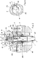
- Fig. 2 is a longitudinal section with details of the upper part of the arbor of the boring mill, with the chuck, with a section of the corresponding operating bar, with the workpiece mounted and with the toolholder in the operating state and also improved according to the invention;
- Fig. 3 is a longitudinal section with details of the intermediate and lower part of the arbor of the boring mill, with the drive pulley, with the tachometer pulley, and with the axially hollow cylinder and piston assembly which moves the operating bar of the chuck;
- Fig. 4 shows further details of the toolholder as in Figure 2, seen in the state of machining of the piece and in section along the line III-III;
- Fig. 5 is a side view, with parts in section, of a toolholder designed for automatic changing and improved according to the invention.
- In Figure 1, the
reference 1 indicates the arbor of the boring mill, which is fixed by thestator part 101 to abase structure 2. Thechuck 3 is mounted on top of the rotating part of the arbor and grips the workpiece with itsjaws 103. With the part which projects downwards from thestator 101, the said rotating part of the arbor carries thetoothed pulley 4 connected with a belt to a driving motor which is not shown, and also carries and is keyed to the body of a cylinder andpiston assembly 5 operating by fluid pressure, with an associatedrotating distributor 6, for the supply of theassembly 5 from fixed points, which in turn is fixed to afixed point 54 of thebase 2 or of other fixed parts. - According to the invention, the piston of the cylinder and
piston assembly 5 is axially hollow and is fixed at the lower end of the vertical bar 7 (Fig. 2) which is also axially hollow (see below) and is fixed by its upper end to themechanism 203 for opening and closing thejaws 103 of thechuck 3. The upper end of thebar 7 projects beyond the previously mentionedmechanism 203 and has inserted in it telescopically, with sufficient clearance, afunnel 8 fixed withclamps 9 in the radial cavities of the body of thechuck 3. The upper shape of the funnel may vary according to the shape of the workpiece, and the funnel may advantageously be associated withreference pieces 10 on which the workpiece P is initially positioned so that it is correctly placed before being gripped by thejaws 103. Thefunnel 8 has the function of extending, and bringing as close as possible to the workpiece, the vertical duct C which passes through thebar 7 and thecorresponding operating cylinder 5, and which is designed for the collection and removal of the chips. - According to the example in Figure 2, the
bar 7 is formed by ahollow rod 107 fixed by its lower end to the piston of the cylinder and piston assembly 5 (see below) and fixed by its upper end to atube 207 on which anextension tube 307 is screwed, theflange 11 integral with the chuck opening andclosing mechanism 203 being clamped between the two tubes. Thetube 307 has externally fittedseals 12 with which it slides with a lateral seal through thepart 303 of the body of the chuck. It is to be understood that thebar 7 may be made with a number of parts different from that described, for example with two parts or with only one part. - The device of a known
type 13, which collects the chips and the cutting fluid from the machining of the piece, which removes the chips to a collection point, and which filters the fluid which is then taken up by suitable pumps (see below) and supplied to the tool-holder, is disposed below the previously mentioned vertical duct C. - In Figure 2, 14 indicates the support which is fixed to the orthogonal movement slide of the boring mill and which is designed to hold securely, with a rapid and known method of attachment, the mounting or
shank 115 of thetoolholder 15, provided with aflange 215 which bears frontally on the underside of the said body. Theflange 215 is normally provided with an offset cavity open at the top for interaction with areference pin 16 carried by thesupport 14, to ensure the centring and consequent connection between the upper end of aduct 17 formed in thetoolholder 15 and the lower end of aduct 18 which is formed in thesupport 14 and abuts against a duct leading from a low-pressure pump 19 which draws the cutting fluid from the reservoir of the device 13 (Fig. 1). The lower end of theduct 17 opens in the intermediate part of the body of thetoolholder 15, of an inclined plane, and supplies the cutting fluid to thetool 315, with known characteristics of pressure and flow. By way of indication, the pressure of the fluid leaving theduct 17 is approximately of the order of 30 bar. - According to the invention, the cutting fluid is also drawn from the reservoir of the
device 13 by apump 20 capable of operating at a very high pressure, for example of the order of at least 130-200 bar, with a flow rate of the order of approximately 30 litres per minute, and the fluid at high pressure is sent through aduct 21 into aduct 22 formed in thesupport 14. Theduct 22 opens on to the lower face of thesupprt 14 and abuts on and is connected to aduct 23 which passes through theflange 215 and which emerges from the latter with a location and direction such that a jet of fluid at high pressure is supplied and passes from the top to the bottom of the workpiece P, runs in the clearance between the duct C and thetoolholder 15, and does not interfere with the jet of fluid at low pressure which is directed against the tool and strikes the chip after its formation, impelling it towards the collection andremoval device 13. - An
adjustable nozzle 24 may be mounted at the lower end of theduct 23. - Figure 4 shows that the jet of fluid at high pressure which emerges from the
duct 23 may be located at the point, easily deducible from practical tests, at which, according to the direction of rotation F of the piece P and to the shape of thetool 315 and/or any other parameters, the chips T tend to accumulate, so that these chips are rapidly struck by the said jet of fluid and compelled to flow downwards. The location of the jet of fluid at high pressure above the tool permits action on those chips which initially tend to rise rather than to fall. - It is to be understood that the location of the jet of fluid at high pressure may be different from that shown, and that a number of jets at high pressure, suitably spaced apart and distributed in the round angle, may be provided, the whole in a way which may be understood and easily applied by engineers working in this field.
- The jet of fluid at high pressure may be directed downwards, parallel to the axis of the arbor or suitably inclined, so that a true vortex is formed in the duct C.
- As an alternative to the above, the
duct 21 may be made to communicate withducts 123 formed in theflange 215 and in the body of thetoolholder 15 and discharging into the lower end of this body, below thetool 315, so that at least one jet of fluid at high pressure, useful for the removal of the chips, is discharged from the lower part of this body, possibly through anadjustable nozzle 124. - According to a preferred embodiment of the invention, a combined supply of jets of fluid at high pressure is provided from both
duct 23 andduct 123, and consequently from both the upper and the lower part of the toolholder. - The advantages derived from the solution described may be summarised as follows. Because of their weight, the chips have a natural tendency to fall. The jet or jets of fluid at high pressure promote the promote the natural removal of the chips, so that no accumulations of chips occurs in the working area of the tool as occurs in the known art, with advantages both in the quality of machining and in the life of the tool. It has been found from long-term tests that the like of the tool is almost doubled by comparison to that of the tools used in boring mills of known type.
- Since all the chips are directed and removed downwards, the chuck of the boring mill remains clean and in the best condition to be served by automatic systems for the supply and removal of the workpieces and the finished pieces.
- With reference to Figure 3, it will be seen that the
drive pulley 4 and thepulley 25 connected to the tachometer unit of a known type, designed for the monitoring of the rotation speed and angular position of the arbor, are keyed to the lower part of therotating part 201 of the arbor. Thepulley 25 is fixed between a pair of flanges 26-126, the latter of which is fixed to therotating part 201, and thepart 107 of thehollow bar 7 projects axially from this assembly. Thebody 105 of the cylinder andpiston assembly 5, provided at its top with thecover 205 and extended below by apart 305 of restricted external section, is fixed coaxially to theflange 26. The axiallyhollow stem 407 of theassembly 5 passes axially and with a lateral seal through theparts part 107 of thebar 7, for example by screwing and with the interposition of abush 29. Thestem 407 of theassembly 5 carries and is integral with thepiston 405 which slides with a lateral seal in thebody 105 and delimits twoopposing pressure chambers piston 405 and of thestem 407 with respect to thebody 105, apin 32, parallel to the axis of theassembly 5, is mounted in an eccentric position on this piston, and projects from both faces of the piston, and can interact withopposite guide recesses cover 205 and on the bottom of thebody 105. Before the upper part of thepin 32 leaves thesocket 33, the lower part of this pin begins to interact with theguide 34, and vice versa. - On the lower
tapered section 305 of the body of theassembly 5, theannular stator 6 of the rotary coupling is mounted rotatably with the interposition of the bearings 35-135, and is secured axially by theflange 36 fixed frontally on thesaid part 305 and is provided on its internal diameter with aseal 37 which interacts to form a seal with the external lateral surface of thestem 407. - On the internal lateral surface of the
stator 6 there are twoannular recesses ducts assembly 5 and whose other open into thechambers stator 6 there are at least twoorifices - The
stator 6 has at its top anannular chamber 47 with aseal 48 on thepart 305 of thebody 5. Thesaid stator 6 has at its bottom a similarannular chamber 49 tightly closed by acover 50 with aseal 51 on theflange 36. The oil with unavoidably penetrates through the seals 40-42 enters thechambers holes 52 so that all the oil is collected in the lower chamber. Suitable radial apertures, not shown, may also be provided on the front surfaces of theflange 36 bearing on thepart 305 of the body of theassembly 5, so that any leakages of oil which pass through theseal 28 are also forced to accumulate in thechamber 49. Through aduct 53 formed in thecover 50, thechamber 49 is subjected to the suction of a drainage pump, not shown, which discharges into the reservoir of the hydraulic power unit connected to the previously mentionedducts - Suitable means are provided to secure the
stator 6 to at least one fixed point of the boring mill or of other fixed parts associated therewith. These means may, for example, consist of afork 54 which interacts with the union of theduct 53 and which is fixed to the frame of thefilter device 13. - In Figure 3, 55 indicates an extension bush fixed coaxially on the lower end of the
stem 407 and provided laterally with anannular collar 155 which, depending on the raised or lowered position of the said stem, interacts alternately with one of the sensors 56-156 fixed laterally on apierced cover 57 through which the said bush passes and which is in turn fixed to thestator 6 of the rotary coupling. - With reference to Figure 5, it will be seen that the
duct 22 for the supply of fluid at high pressure, formed in thebody 14 of the support for thetoolholder 15, abuts on thepin 16 or on a supplementary pin fixed on thesaid support 14 or on an insertedpart 114. Thepin 16 is provided with an axialblind hole 58, which opens laterally on the visible section of the said pin with ahole 158, above which the said pin is provided with anannular seal 59. Thehole 23 opens laterally in thehole 60 of thebase piece 215 in which thepin 16 is inserted, and, by contrast with the solution shown in Figure 2, opens on the inclined plane of the toolholder on which thetool 315 is disposed, in such a way that there is no interference with the fluid at low pressure which emerges from thehole 17 and is applied to the said tool. - The
hole 123 which discharges from the lower end of the toolholder is branched from thehole 23. - When the toolholder is designed for automatic changing, the
collar 61 designed to interact with the change manipulating gripper, which is not shown, is disposed under thebase piece 215 and not above as in the known art. With this solution, the said manipulating gripper is prevented from interfering with thepin 16, especially in the case in which more than one toolholder structure of the type illustrated in Figure 5 is disposed beside each other on the same support slide. - It is to be understood that the description refers to certain preferred and non-unique embodiments of the invention, to which numerous variations and modifications may be made, especially as regards construction, within the scope of the claims as defined below. In the following claims, the references in parantheses have the sole purpose of facilitating the reading of the said claims, and therefore should not be interpreted as in any way restrictive to the scope of protection of the said claims.
Claims (23)
- Method for the controlled removal of chips in a boring mill of the type comprising a chuck (3) for gripping a workpiece (P); a cutting tool (315) for cutting said workpiece (P); chuck operating means comprising a bar (7) for operating said said chuck (3); cylinder and piston means (5) for the axial movement of said bar(3); said chuck operating means (5, 7) being located below said workpiece (P); means (17, 23, 123) disposed above said workpiece (P) for feeding a cutting fluid to said workpiece (P) during the cutting operation; and means (13) disposed below said chuck operating means (5,7) for collecting said cutting fluid, the method comprising the steps of:- Forming a vertical duct (C) through said chuck operating means (5,7) open at the top end next to the said workpiece (P) held by said chuck (3), and open at its bottom end over said cutting fluid collecting means (13);- directing at the cutting zone at least one first jet of cutting fluid to lubricate and cool the tool (315).- downwardly directing at the cutting zone at least one second jet of cutting fluid at a pressure much higher than that of said first jet.- said second jet being so directed as to not interfere with said fist jet or jets, said second jet or jets acting directly on the chips formed during the boring operation so as to sweep away said chips along said vertical duct (C) up to said cutting fluid collecting means (13),- removing by filtration said chips from said cutting fluid, and- recycling said filtered cutting fluid.
- Method according to Claim 1, in which the pressure of the jet or jets of fluid directed against the chips for their removal downwards is approximately of the order of 130-200 bar.
- Method according to Claim 1, in which the jet or jets of fluid at high pressure which remove the chips are supplied at a height above that at which the tool or tools (315) operate.
- Method according to Claim 1, in which the jet or jets of fluid at high pressure which remove the chips are supplied at a height substantially equal to that at which the tools (315) operate.
- Method according to Claim 1, in which the jet or jets of fluid at high pressure which remove the chips are supplied at a height lower than that at which the tools (315) operate.
- Method according to Claim 1, in which the jets of fluid at high pressure which remove the chips are supplied in any combination of the conditions claimed in Claims 3, 4 and 5.
- Method according to the preceding Claims, in which the jet or jets of fluid at high pressure which remove the chips are vertical or substantially vertical.
- Method according to Claims 1 to 6, in which the jet or jets of fluid at high pressure which remove the chips are suitably inclined with respect to the vertical, so as to create a vortex which improves the downward transport of the chips.
- Boring mill comprising a chuck (3) provided with clamps or gripping jaws (103) for gripping a workpiece (P); holder means (14) for a cutting tool (315) for cutting said workpiece (P); chuck operating means comprising a bar (7) for operating said said chuck (3) and cylinder and piston means (51) for the axial movement of said bar (7); said chuck operating means (5,7) being located below said workpiece (P) and being all made with an axially hollow shape so as to define a vertical axial duct (C) which is open at the top end next to the workpiece (P) held by the chuck (3) and which is open at the opposite, bottom end over means (13) for collecting cutting fluid; first cutting fluid supplying means (17) carried by said cutting tool holder for directing at the cutting zone at least one first jet of cutting fluid to lubricate and cool the tool; second cutting fluid supplying means (23) carried by said cutting tool holder for downwardly directing at the cutting zone at least one second jet of cutting fluid at a pressure much higher than that of said first jet; the means (13) for collecting said cutting fluid being disposed below said chuck operating means; means for removing by filtration said chips from said collected cutting fluid, and pump means (19,20) for recycling said filtered cutting fluid.
- Boring mill according to Claim 9, in which the hollow bar (7), which operates the mechanism for opening and closing the clamps or gripping jaws (103) of the chuck, extends beyond this mechanism to approach the workpiece as closely as possible and projects from the body of the chuck with the interposition of lateral sealing means (12-303).
- Boring mill according to Claim 9, in which a funnel (8) is mounted telescopically in the upper end of the hollow bar (7) which operates the chuck, and has its widened upper end fixed by means of clamps (9) to the body of the said chuck, so that the duct for collecting and removing the chips is brought as close as possible to the workpiece.
- Boring mill according to Claim 11, in which the upper end of the funnel (8) carries and is integral with reference pieces (10) on which the workpiece is supported so that the workpiece is correctly placed before being gripped by the jaws of the chuck.
- Boring mill according to Claim 9, characterized in that the cylinder and piston assembly (5) for operating the bar (7) of the chuck (3) is fixed coaxially by a closed end of the body (105) to the lower end of the rotating part (201) of the arbor (1), while the upper end of its hollow stem (407), which extends from the said body with a latera seal, is fixed to the said bar (7), the body of the said assembly (5) being provided with a lower tapered section (305) in which are formed and on which are laterally open ducts (43-44) which are connected to the two pressure chambers (30-31) of the said assembly (5) and which are connected by means of seals (40-41-42) to a pair of ducts (38-39-45-46) formed in an annular stator (6) mounted rotatably with the interposition of bearings (35-135) on the lower section of the body of the said assembly (5) and connected to any fixed structure (54) of the boring mill or of parts associated with it, drainage cavities (47-49-52) being formed in the said stator and closed externally by seals (48-51), the cavity (49) disposed at the lowest height, in which all the leaked oil which penetrates through the various seals is collected by gravity, being connected to a duct (53) and to suction means which remove the said leaked oil.
- Boring mill according to Claim 13, characterized in that the lower end of the hollow stem (407) of the cylinder and piston assembly (5) which operates the bar of the chuck extends with a lateral seal from the tapered lower section of the body of the said assembly (5) and carries and is coaxially fixed to an extension bush (55) which passes through a pierced cover (57) fixed to the stator (6) of the rotary coupling for the supply of the said assembly, on which cover are laterally mounted sensors (56-156) which detect the height of an annular collar (155) of the said bush and which signal the condition of raising or lowering of the bar to the electronic circuits controlling the boring mill.
- Boring mill according to Claim 13, characterized in that the piston (405) of the cylinder and piston assembly (5) which operates the bar (7) of the chuck has mounted on it, perpendicularly and in a offset position, one or more pins (32-132) which interact with corresponding sockets (33-34) formed in the body of the said assembly (5) to prevent relative rotary movements between the components of the said cylinder and piston assembly and to prevent the transmission of such relative movements to the bar.
- Boring mill according to the preceding claims, in which the high-pressure pump (20) abuts on at least one duct (22) formed in the support (14) with the socket for the attachment of the toolholder (15), and this duct opens on to the lower face of the said support and is designed in any suitable way to be connected to at least one further duct (23) formed in the flange (215) of the toolholder and which opens in at least one of any sutable points of the toolholder with a disposition and direction such that a jet of fluid at high pressure is supplied which strikes the chips after their formation and compels them to fall towards the means of removal and filtration (13).
- Boring mill according to Claim 16, in which the duct of the fluid at high pressure (23) formed in the flange (215) of the toolholder is open on the lower face of the flange.
- Boring mill according to Claim 16, in which the duct (23) through which the fluid at high pressure passes and which is formed in the flange (215) of the toolholder is extended downwards with an extension (123) which passes longitudinally through the body of the toolholder (15) and which opens on the lower end of this body, below the tool or tools (315) and with a direction suitable for the removal of the chips.
- Boring mill according to Claim 16, in which the duct (23) through which the fluid at high pressure passes and which is formed in the flange (215) of the toolholder is extended downwards with an extension which opens on an inclined plane with which the toolholder is normally provided, above the tool or substantially at the same height as the tool, but at all events in such a way that there is no interference with the jet of fluid at low pressure directed against the said tool.
- Boring mill according to Claim 9, characterized by any combination of the solutions described in Claims 17, 18 and 19.
- Boring mill according to the preceding claims, characterized in that the said lower face of the support (14) with the socket for the attachment of the toolholder (15) has fixed to it a projecting pin (16), parallel to the said socket, the pin having a hole (58) whose upper end is connected to the duct (22) abutting on the pump for delivery of the fluid at high pressure and whose lower end opens laterally on the projecting end part of the said pin, below and annular seal (59) with which the said part of the pin is inserted sealingly in a corresponding socket (60) of the flange (215) of the toolholder, into which socket the duct (23) opens and by itself or with branches (123), if any, discharges the fluid at high pressure which removes the chips.
- Boring mill according to the preceding claims, particularly according to Claim 21, characterized in that, if the toolholder is provided with a collar (61) for automatic changing by a suitable manipulator, this collar is disposed below the base piece (215) with the upper attachment cone of the toolholder, so that, during the changing operation, the said manipulator does not have to interfere with the pins for the supply of the fluid at high pressure.
- Boring mill according to the preceding claims, in which adjustable nozzles (24-124) may be mounted on the ends of the corresponding duct or ducts (23-123) for the supply of the fluid at high pressure for the removal of the chips.
Applications Claiming Priority (2)
| Application Number | Priority Date | Filing Date | Title |
|---|---|---|---|
| IT93BO000207A IT1266345B1 (en) | 1993-05-10 | 1993-05-10 | METHOD FOR THE CONTROLLED EVACUATION OF MACHINING CHIPS IN VERTICAL LATHES AND LATHES MADE WITH THIS METHOD. |
| ITBO930207 | 1993-05-10 |
Publications (2)
| Publication Number | Publication Date |
|---|---|
| EP0624429A1 EP0624429A1 (en) | 1994-11-17 |
| EP0624429B1 true EP0624429B1 (en) | 1997-04-16 |
Family
ID=11339020
Family Applications (1)
| Application Number | Title | Priority Date | Filing Date |
|---|---|---|---|
| EP94106898A Expired - Lifetime EP0624429B1 (en) | 1993-05-10 | 1994-05-03 | Method for the controlled removal of chips in boring mills and boring mills produced with this method |
Country Status (7)
| Country | Link |
|---|---|
| US (1) | US5560270A (en) |
| EP (1) | EP0624429B1 (en) |
| JP (1) | JP3633955B2 (en) |
| AT (1) | ATE151677T1 (en) |
| DE (1) | DE69402599T2 (en) |
| ES (1) | ES2102723T3 (en) |
| IT (1) | IT1266345B1 (en) |
Families Citing this family (6)
| Publication number | Priority date | Publication date | Assignee | Title |
|---|---|---|---|---|
| US6209429B1 (en) * | 1999-06-28 | 2001-04-03 | Xerox Corporation | Machining hollow cylinders |
| US6539827B2 (en) * | 2000-03-13 | 2003-04-01 | Japan Machine Tools, Corp. | Apparatus and method for discharging chips from a lathe |
| GB0213019D0 (en) * | 2002-06-06 | 2002-07-17 | Clark John | Drilling attachment |
| CN112589532B (en) * | 2020-12-03 | 2022-02-22 | 深圳市速锋科技股份有限公司 | Machine tool spindle and cutter tightness detection device |
| JP7047191B1 (en) * | 2021-05-10 | 2022-04-04 | ヤマザキマザック株式会社 | How to use the coolant discharge device, work holding device, work rotation device, machine tool, and coolant discharge device |
| CN114799974B (en) * | 2022-06-27 | 2022-09-23 | 徐州万达回转支承有限公司 | Portable slewing bearing side spot facing work positioning mechanism |
Family Cites Families (9)
| Publication number | Priority date | Publication date | Assignee | Title |
|---|---|---|---|---|
| US2033946A (en) * | 1934-11-15 | 1936-03-17 | Ideal Roller & Mfg Company | Apparatus for trimming cylinders |
| US4322992A (en) * | 1980-05-02 | 1982-04-06 | Otis Engineering Corporation | Chip washing system |
| JPS5976749A (en) * | 1982-10-23 | 1984-05-01 | Okuma Mach Works Ltd | Washing of working surface |
| US4475853A (en) * | 1982-12-30 | 1984-10-09 | Deere & Company | Rotary tool and guide |
| JPS6085803A (en) * | 1983-10-14 | 1985-05-15 | Mitsubishi Heavy Ind Ltd | Chip shredding method and its device |
| JPS614646A (en) * | 1984-06-20 | 1986-01-10 | Kishida Hisao | Chip removal by high pressure flow |
| JPS61203246A (en) * | 1985-03-04 | 1986-09-09 | Tokiwa Seisakusho:Kk | Device for recovering discontinuous chips |
| JPH067877Y2 (en) * | 1988-02-27 | 1994-03-02 | シチズン時計株式会社 | Waste material collection device |
| DE3838318A1 (en) * | 1988-11-11 | 1990-05-17 | Krupp Widia Gmbh | TOOLING SYSTEM |
-
1993
- 1993-05-10 IT IT93BO000207A patent/IT1266345B1/en active IP Right Grant
-
1994
- 1994-05-03 ES ES94106898T patent/ES2102723T3/en not_active Expired - Lifetime
- 1994-05-03 DE DE69402599T patent/DE69402599T2/en not_active Expired - Lifetime
- 1994-05-03 AT AT94106898T patent/ATE151677T1/en active
- 1994-05-03 EP EP94106898A patent/EP0624429B1/en not_active Expired - Lifetime
- 1994-05-05 US US08/238,739 patent/US5560270A/en not_active Expired - Lifetime
- 1994-05-10 JP JP11965894A patent/JP3633955B2/en not_active Expired - Fee Related
Also Published As
| Publication number | Publication date |
|---|---|
| EP0624429A1 (en) | 1994-11-17 |
| ATE151677T1 (en) | 1997-05-15 |
| JPH06320315A (en) | 1994-11-22 |
| DE69402599D1 (en) | 1997-05-22 |
| DE69402599T2 (en) | 1997-10-09 |
| ES2102723T3 (en) | 1997-08-01 |
| JP3633955B2 (en) | 2005-03-30 |
| US5560270A (en) | 1996-10-01 |
| ITBO930207A0 (en) | 1993-05-10 |
| IT1266345B1 (en) | 1996-12-27 |
| ITBO930207A1 (en) | 1994-11-10 |
Similar Documents
| Publication | Publication Date | Title |
|---|---|---|
| EP0988926A2 (en) | A machining method | |
| KR20020011460A (en) | a deburring machine for work | |
| HK1039589A1 (en) | Maching method and mist supplying apparatus for use in the method | |
| CN213195695U (en) | Drilling machine | |
| EP0624429A1 (en) | Method for the controlled removal of chips in boring mills and boring mills produced with this method | |
| US5327979A (en) | Coolant through spindle device | |
| CN118492538B (en) | A medium-speed wire cutting machine tool for automobile stamping parts | |
| CN113084588A (en) | Drilling machine convenient to clearance sweeps | |
| JP3745023B2 (en) | Machine tool cooling dust collector | |
| KR100864052B1 (en) | Vertical Machining Center | |
| CN113787361B (en) | Horizontal multi-spindle deep hole drilling machine | |
| KR910007273B1 (en) | Coolant separator of machine tool | |
| US4322992A (en) | Chip washing system | |
| JPH04360710A (en) | Tool holder assembly having filler device | |
| KR20100102337A (en) | Cutting oil filtering device | |
| CN110340415B (en) | Shaft groove cutting machine | |
| CN219725300U (en) | Clamping mechanism for construction | |
| CN209288414U (en) | It is a kind of for processing the tapping machine of hole making drill | |
| CN218696585U (en) | Machine tool with scrap removing function | |
| CN116160041A (en) | Horizontal automatic drilling machine tool special for automobile hub | |
| CN116475848A (en) | Multi-working-procedure integrated machine tool | |
| CN209849894U (en) | Vertical numerical control boring machine | |
| KR102575667B1 (en) | Universal lathe automatic coolant supply system | |
| US3559511A (en) | Drill coolant method and apparatus | |
| CN221087369U (en) | Trepanning jig for blind hole boring bar |
Legal Events
| Date | Code | Title | Description |
|---|---|---|---|
| PUAI | Public reference made under article 153(3) epc to a published international application that has entered the european phase |
Free format text: ORIGINAL CODE: 0009012 |
|
| AK | Designated contracting states |
Kind code of ref document: A1 Designated state(s): AT BE CH DE DK ES FR GB GR IE LI LU MC NL PT SE |
|
| 17P | Request for examination filed |
Effective date: 19941123 |
|
| GRAG | Despatch of communication of intention to grant |
Free format text: ORIGINAL CODE: EPIDOS AGRA |
|
| 17Q | First examination report despatched |
Effective date: 19960702 |
|
| GRAH | Despatch of communication of intention to grant a patent |
Free format text: ORIGINAL CODE: EPIDOS IGRA |
|
| GRAH | Despatch of communication of intention to grant a patent |
Free format text: ORIGINAL CODE: EPIDOS IGRA |
|
| GRAA | (expected) grant |
Free format text: ORIGINAL CODE: 0009210 |
|
| AK | Designated contracting states |
Kind code of ref document: B1 Designated state(s): AT BE CH DE DK ES FR GB GR IE LI LU MC NL PT SE |
|
| PG25 | Lapsed in a contracting state [announced via postgrant information from national office to epo] |
Ref country code: NL Effective date: 19970416 Ref country code: LI Free format text: LAPSE BECAUSE OF FAILURE TO SUBMIT A TRANSLATION OF THE DESCRIPTION OR TO PAY THE FEE WITHIN THE PRESCRIBED TIME-LIMIT Effective date: 19970416 Ref country code: GR Free format text: LAPSE BECAUSE OF FAILURE TO SUBMIT A TRANSLATION OF THE DESCRIPTION OR TO PAY THE FEE WITHIN THE PRESCRIBED TIME-LIMIT Effective date: 19970416 Ref country code: DK Effective date: 19970416 Ref country code: CH Free format text: LAPSE BECAUSE OF FAILURE TO SUBMIT A TRANSLATION OF THE DESCRIPTION OR TO PAY THE FEE WITHIN THE PRESCRIBED TIME-LIMIT Effective date: 19970416 Ref country code: BE Effective date: 19970416 Ref country code: AT Effective date: 19970416 |
|
| REF | Corresponds to: |
Ref document number: 151677 Country of ref document: AT Date of ref document: 19970515 Kind code of ref document: T |
|
| REG | Reference to a national code |
Ref country code: CH Ref legal event code: EP |
|
| PG25 | Lapsed in a contracting state [announced via postgrant information from national office to epo] |
Ref country code: LU Free format text: LAPSE BECAUSE OF NON-PAYMENT OF DUE FEES Effective date: 19970503 |
|
| REF | Corresponds to: |
Ref document number: 69402599 Country of ref document: DE Date of ref document: 19970522 |
|
| PG25 | Lapsed in a contracting state [announced via postgrant information from national office to epo] |
Ref country code: IE Free format text: LAPSE BECAUSE OF NON-PAYMENT OF DUE FEES Effective date: 19970616 |
|
| PG25 | Lapsed in a contracting state [announced via postgrant information from national office to epo] |
Ref country code: PT Effective date: 19970716 |
|
| REG | Reference to a national code |
Ref country code: IE Ref legal event code: FG4D Free format text: 73349 |
|
| REG | Reference to a national code |
Ref country code: ES Ref legal event code: FG2A Ref document number: 2102723 Country of ref document: ES Kind code of ref document: T3 |
|
| ET | Fr: translation filed | ||
| NLV1 | Nl: lapsed or annulled due to failure to fulfill the requirements of art. 29p and 29m of the patents act | ||
| REG | Reference to a national code |
Ref country code: CH Ref legal event code: PL |
|
| PG25 | Lapsed in a contracting state [announced via postgrant information from national office to epo] |
Ref country code: MC Effective date: 19971130 |
|
| PLBE | No opposition filed within time limit |
Free format text: ORIGINAL CODE: 0009261 |
|
| STAA | Information on the status of an ep patent application or granted ep patent |
Free format text: STATUS: NO OPPOSITION FILED WITHIN TIME LIMIT |
|
| 26N | No opposition filed | ||
| PG25 | Lapsed in a contracting state [announced via postgrant information from national office to epo] |
Ref country code: GB Free format text: LAPSE BECAUSE OF NON-PAYMENT OF DUE FEES Effective date: 19980503 |
|
| GBPC | Gb: european patent ceased through non-payment of renewal fee |
Effective date: 19980503 |
|
| PGFP | Annual fee paid to national office [announced via postgrant information from national office to epo] |
Ref country code: ES Payment date: 20100426 Year of fee payment: 17 |
|
| PGFP | Annual fee paid to national office [announced via postgrant information from national office to epo] |
Ref country code: DE Payment date: 20100618 Year of fee payment: 17 |
|
| PGFP | Annual fee paid to national office [announced via postgrant information from national office to epo] |
Ref country code: SE Payment date: 20100520 Year of fee payment: 17 |
|
| REG | Reference to a national code |
Ref country code: DE Ref legal event code: R119 Ref document number: 69402599 Country of ref document: DE |
|
| REG | Reference to a national code |
Ref country code: DE Ref legal event code: R119 Ref document number: 69402599 Country of ref document: DE |
|
| REG | Reference to a national code |
Ref country code: SE Ref legal event code: EUG |
|
| PGFP | Annual fee paid to national office [announced via postgrant information from national office to epo] |
Ref country code: FR Payment date: 20120625 Year of fee payment: 19 |
|
| REG | Reference to a national code |
Ref country code: ES Ref legal event code: FD2A Effective date: 20121116 |
|
| PG25 | Lapsed in a contracting state [announced via postgrant information from national office to epo] |
Ref country code: ES Free format text: LAPSE BECAUSE OF NON-PAYMENT OF DUE FEES Effective date: 20110504 |
|
| PG25 | Lapsed in a contracting state [announced via postgrant information from national office to epo] |
Ref country code: SE Free format text: LAPSE BECAUSE OF NON-PAYMENT OF DUE FEES Effective date: 20110504 |
|
| PG25 | Lapsed in a contracting state [announced via postgrant information from national office to epo] |
Ref country code: DE Free format text: LAPSE BECAUSE OF NON-PAYMENT OF DUE FEES Effective date: 20111130 |
|
| REG | Reference to a national code |
Ref country code: FR Ref legal event code: ST Effective date: 20140131 |
|
| PG25 | Lapsed in a contracting state [announced via postgrant information from national office to epo] |
Ref country code: FR Free format text: LAPSE BECAUSE OF NON-PAYMENT OF DUE FEES Effective date: 20130531 |