EP0623971B1 - Verbesserte Methode zur Verbindung von Heizelementen - Google Patents
Verbesserte Methode zur Verbindung von Heizelementen Download PDFInfo
- Publication number
- EP0623971B1 EP0623971B1 EP94107233A EP94107233A EP0623971B1 EP 0623971 B1 EP0623971 B1 EP 0623971B1 EP 94107233 A EP94107233 A EP 94107233A EP 94107233 A EP94107233 A EP 94107233A EP 0623971 B1 EP0623971 B1 EP 0623971B1
- Authority
- EP
- European Patent Office
- Prior art keywords
- insulating support
- sheet
- apertures
- terminal ends
- tongues
- Prior art date
- Legal status (The legal status is an assumption and is not a legal conclusion. Google has not performed a legal analysis and makes no representation as to the accuracy of the status listed.)
- Expired - Lifetime
Links
- 238000000034 method Methods 0.000 title claims description 25
- 210000002105 tongue Anatomy 0.000 claims description 15
- 239000004020 conductor Substances 0.000 description 4
- 238000005516 engineering process Methods 0.000 description 3
- 238000004519 manufacturing process Methods 0.000 description 2
- 238000010276 construction Methods 0.000 description 1
- 238000005553 drilling Methods 0.000 description 1
- 238000010438 heat treatment Methods 0.000 description 1
- 238000009776 industrial production Methods 0.000 description 1
- 239000010445 mica Substances 0.000 description 1
- 229910052618 mica group Inorganic materials 0.000 description 1
- 238000002360 preparation method Methods 0.000 description 1
- 230000000717 retained effect Effects 0.000 description 1
- 238000005476 soldering Methods 0.000 description 1
Images
Classifications
-
- H—ELECTRICITY
- H01—ELECTRIC ELEMENTS
- H01R—ELECTRICALLY-CONDUCTIVE CONNECTIONS; STRUCTURAL ASSOCIATIONS OF A PLURALITY OF MUTUALLY-INSULATED ELECTRICAL CONNECTING ELEMENTS; COUPLING DEVICES; CURRENT COLLECTORS
- H01R9/00—Structural associations of a plurality of mutually-insulated electrical connecting elements, e.g. terminal strips or terminal blocks; Terminals or binding posts mounted upon a base or in a case; Bases therefor
- H01R9/22—Bases, e.g. strip, block, panel
- H01R9/24—Terminal blocks
- H01R9/2491—Terminal blocks structurally associated with plugs or sockets
-
- H—ELECTRICITY
- H05—ELECTRIC TECHNIQUES NOT OTHERWISE PROVIDED FOR
- H05B—ELECTRIC HEATING; ELECTRIC LIGHT SOURCES NOT OTHERWISE PROVIDED FOR; CIRCUIT ARRANGEMENTS FOR ELECTRIC LIGHT SOURCES, IN GENERAL
- H05B3/00—Ohmic-resistance heating
- H05B3/02—Details
- H05B3/06—Heater elements structurally combined with coupling elements or holders
-
- H—ELECTRICITY
- H05—ELECTRIC TECHNIQUES NOT OTHERWISE PROVIDED FOR
- H05B—ELECTRIC HEATING; ELECTRIC LIGHT SOURCES NOT OTHERWISE PROVIDED FOR; CIRCUIT ARRANGEMENTS FOR ELECTRIC LIGHT SOURCES, IN GENERAL
- H05B3/00—Ohmic-resistance heating
- H05B3/20—Heating elements having extended surface area substantially in a two-dimensional plane, e.g. plate-heater
- H05B3/22—Heating elements having extended surface area substantially in a two-dimensional plane, e.g. plate-heater non-flexible
- H05B3/26—Heating elements having extended surface area substantially in a two-dimensional plane, e.g. plate-heater non-flexible heating conductor mounted on insulating base
-
- H—ELECTRICITY
- H01—ELECTRIC ELEMENTS
- H01R—ELECTRICALLY-CONDUCTIVE CONNECTIONS; STRUCTURAL ASSOCIATIONS OF A PLURALITY OF MUTUALLY-INSULATED ELECTRICAL CONNECTING ELEMENTS; COUPLING DEVICES; CURRENT COLLECTORS
- H01R31/00—Coupling parts supported only by co-operation with counterpart
- H01R31/02—Intermediate parts for distributing energy to two or more circuits in parallel, e.g. splitter
Definitions
- the present invention relates to a method for making connections between electric circuits disposed on an insulating support, including the steps of applying a plurality of terminals to said insulating support, said step of applying said plurality of terminals is carried out by mounting at least one conductive member on said insulating support by inserting projections extending therefrom into apertures formed in said insulating support, and mechanically and electrically connecting terminal ends of said electric circuits to said plurality of terminals.
- connection of this type is generally known, and is employed in practically identical manner by different manufacturers, apart from certain marginal variations mainly due to different physical configurations of the resistor elements and the associated supports.
- This technology is substantially based on a manufacturing cycle which shall be briefly outlined in the following in order to facilitate comparison to the method of the present invention to be described subsequently.
- the first step consists in forming the insulating support with a number of apertures at locations corresponding to the terminal ends of the resistance circuits; the second step consists in connecting the terminal ends of the resistance circuits to conductor elements adjacent the locations of respective apertures; the third step consists in rivetting the conductor elements to the insulating support by means of rivets passing through respective apertures, to thereby establish reliable mechanical and electrical connections of the conductor elements to the associated rivets; and the fourth step consists in connecting the rivets to respective power supply terminals in a per se known manner, for instance by soldering.
- reference document DE-A-30 42 417 discloses a method for the connection of heater elements with terminals.
- the terminals are part of a conductive member which comprises a rivet type projection.
- the rivet type projection is inserted in apertures of the insulating support.
- One end of the rivet type projection is formed like a flange and abuts against the insulating support. The other end projects through the insulating support.
- the diameter of the rivet type projection is about equal to the diameter of the apertures in the insulating support.
- the projecting end of the rivet type projection is bent over in order to clamp the insulating support between the flange and the bent over end of the rivet type projection. Even though the number of assembly steps is reduced, this method is still not satisfactory.
- said conductive member being a sheet member being formed with a plurality of outwards projecting tongues, and that said sheet member being positioned so that said tongues coincide with respective terminal ends of said electric circuits, said tongues being bent 180° upon themselves to form two legs for said terminal ends to be received therebetween, and that said sheet member is divided into several separate sheet elements by the execution of multiple cuts at selected locations and the removal of sheet sections extending between adjacent cuts, and that said projections inserted into said apertures and projecting from said insulating support are bent over the edges of said apertures in a locking fit.
- a method according to the present invention is preferably carried out by employing an electric circuit disposed on an insulating support and connected to a flat power supply terminal according to claim 5.
- the method according to the invention is substantially based on the provision that the connections between power supply conductors and the terminal ends of electric circuits are made by using one-piece conductive sheet members adapted to be automatically mounted in apertures suitably formed in an insulating support and to be similarly connected to the terminal ends of electric circuits; for a better understanding of the invention, it shall be supposed that these electric circuits are resistor circuits, it being understood, however, that the invention is similarly applicable to any kind of electric circuits, and particularly to resistor circuits for air heating purposes.
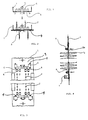
- an insulating support typically a mica plate, supporting one or several elongate resistor circuits 2 mounted in respective rows of apertures suitably formed therein. At the ends of support 1, each resistor circuit terminates in respective terminal ends 2a projecting from support 1 at the same side thereof.
- a single preferably metallic conductive sheet member 5 of elongate shape is attached to one or each end portion 3 of support 1 provided with suitable apertures 4.
- Each sheet member 5 is pre-shaped to present a plurality of tongues 6 projecting from its plane at right angles thereto to coincide with terminal ends 2a for connection there to, and a number of orthogonally extending projections to be received in apertures 4.
- tongues 6 are formed on conductive sheet member 5 at sufficiently wide spacings.
- tongues 6 are pre-bent at 180° upon themselves to thus form a pair of legs adapted to embrace respective terminal ends 2a.
- the projections extending from conductive sheet member 5 are inserted into apertures 4 of insulating support 1 and bent over the edges thereof so as to securely fix the sheet member on the support.
- Sheet member 5 is additionally provided with flat terminal elements 7 likewise projecting therefrom at right angles and adapted to be used as male contacts in flat plug connectors.
- terminal ends 2a are introduced between the pairs of legs formed by the tongues 6 of sheet member 5 (fig. 4).
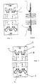
- sheet member 5 is divided into several separate sheet elements 6a, 6b, 6c by performing, preferably simultaneously, multiple cuts at selected locations, and removing the sheet sections between adjacent cuts (fig.7).
- the locations of the cuts are selected so that
- sheet member 5 may be cut to provide a centrally located sheet element 6c permitting to selectively connect two separate resistor circuits in series, or to connect the two circuits to the electric power supply by using the flat terminal element 7 provided on sheet element 6c.
- sheet element 6c may be simplified for solely connecting two resistor circuits in series, without the provision of any external connections.
- the described method may thus be accomplished by the operations of a) connecting and/or interconnecting electric circuits at selected locations thereof by means of a single conductive sheet member secured to the insulating support, and b), dividing the conductive sheet member into several separate sheet elements adapted to be selectively connected to one or more of the electric circuits, with the possibility of performing these operations in a fully automatized process without any manual intervention.
Landscapes
- Resistance Heating (AREA)
- Multi-Conductor Connections (AREA)
Claims (5)
- Verfahren zum Herstellen von Verbindungen zwischen elektrischen Schaltungen, die auf einem isolierenden Träger (3) angeordnet sind, welches Verfahren die Schritte des Anbringens einer Vielzahl von Anschlußenden (7) auf dem isolierenden Träger (3) einschließt, wobei der Schritt des Anbringens einer Vielzahl von Anschlüssen (7) durch Montieren von zumindest einem leitenden Bauteil (5) auf dem isolierenden Träger (1) durch Einsetzen von Vorsprüngen, die sich davon ausgehend in die Öffnungen (4) hineinerstrecken, die in dem isolierenden Träger (3) eingeformt sind, und durch mechanisches und elektrisches leitendes Verbinden der Anschlußenden und der elektrischen Schaltung mit der Vielzahl von Anschlüssen (7) durchgeführt wird,
dadurch gekennzeichnet,daß das leitende Bauteil ein blattförmiges Bauteil ist, welches eine Vielzahl von nach außen vorspringenden Zungen (6) aufweist,und daß das blattförmige Bauteil so angeordnet ist, daß die Zungen (6) mit den zugehörigen Anschlußenden (2a) der elektrischen Schaltungen (2) zusammentrifft, wobei die Zungen (6) um 180° auf sich selbst umgebogen werden, um zwei Schenkel für die Anschlußenden (2a) zu bilden, die dazwischen aufgenommen werden sollen,und daß das blattförmige Bauteil (5) in mehrere getrennte blattförmige Elemente (6a, 6b, 6c) unterteilt ist durch mehrfache Schnitte an vorherbestimmten Stellen und durch das Entfernen der blattförmigen Abschnitte, die sich zwischen den angrenzenden Schnitten erstrecken, unddaß die Vorsprünge, die in die Öffnungen (4) eingesetzt werden und von dem isolierenden Träger vorspringen, über die Kante die Öffnungen umgebogen werden, um einen Klemmsitz zu erzeugen. - Verfahren nach Anspruch 1,
dadurch gekennzeichnet,
daß zumindest ein Paar von getrennten blattförmigen Elementen (6a, 6b) vorgesehen ist, um die Anschlußenden (2a) von zumindest einem der elektrischen Schaltkreise (2) zu verbinden, wobei jedes der blattförmigen Elemente mit zumindest einem flachen Anschlußelement (7) versehen ist. - Verfahren nach einem der vorangegangenen Ansprüche,
dadurch gekennzeichnet,
daß zumindest ein getrenntes blattförmiges Element (6c) mit zumindest einem Paar von Anschlußenden (2a) von zugehörigen unterschiedlichen elektrischen Schaltkreiselementen (2) verbunden ist, und mit einem oder mehreren flachen Anschlußelementen (7) versehen sein kann. - Verfahren nach einem der vorangegangenen Ansprüche,
dadurch gekennzeichnet,
daß es durch eine vollautomatische Anlage durchgeführt wird. - Ein elektrischer Schaltkreis (2), der auf einem isolierenden Träger (3) angeordnet ist und mit flachen Stromversorgungsanschlüssen (7) verbunden ist, wobei die Anschlüsse (7) sich von einem leitenden Bauteil (5) aus erstrecken, welches auf dem isolierenden Träger (3) angebracht ist durch Einsetzen von Vorsprüngen, die sich davon ausgehend erstrecken in Öffnungen (4), die in den isolierenden Träger (3) eingeformt sind,
dadurch gekennzeichnet,
daß das leitende Bauteil (5) ein blattförmiges Bauteil ist, welches mit einer Vielzahl von nach außen sich erstreckenden Zungen (6) versehen ist, und daß das blattförmige Bauteil so angeordnet ist, daß Zungen (6) mit zugehörigen Anschlußenden (2a) der elektrischen Schaltkreise (2) zusammentreffen, wobei die Zungen (6) um 180° auf sich selbst umgebogen sind, um zwei Schenkel zu bilden, zwischen welchen die Anschlußenden (2a) aufgenommen werden, und daß das blattförmige Bauteil (5) in verschiedene getrennte blattförmige Elemente (6a, 6b, 6c), nachdem es auf dem isolierenden Träger (3) montiert ist, durch das Ausführen von mehrfachen Schnitten an vorbestimmten Stellen unterteilt ist, und daß die blattförmigen Abschnitte, die sich zwischen den angrenzenden Schnitten erstrecken, entfernt werden, und daß die Vorsprünge, welche in die Öffnung (4) eingesetzt sind und von dem isolierenden Träger vorstehen, über die Kanten der Öffnungen in einen Klemmsitz umgebogen sind.
Applications Claiming Priority (2)
| Application Number | Priority Date | Filing Date | Title |
|---|---|---|---|
| ITPN930032 | 1993-05-07 | ||
| IT93PN000032A IT1268522B1 (it) | 1993-05-07 | 1993-05-07 | Procedimento perfezionato per la connessione di elementi riscaldanti |
Publications (3)
| Publication Number | Publication Date |
|---|---|
| EP0623971A2 EP0623971A2 (de) | 1994-11-09 |
| EP0623971A3 EP0623971A3 (de) | 1995-01-11 |
| EP0623971B1 true EP0623971B1 (de) | 1996-09-04 |
Family
ID=11394796
Family Applications (1)
| Application Number | Title | Priority Date | Filing Date |
|---|---|---|---|
| EP94107233A Expired - Lifetime EP0623971B1 (de) | 1993-05-07 | 1994-05-09 | Verbesserte Methode zur Verbindung von Heizelementen |
Country Status (4)
| Country | Link |
|---|---|
| EP (1) | EP0623971B1 (de) |
| DE (1) | DE69400461T2 (de) |
| ES (1) | ES2094587T3 (de) |
| IT (1) | IT1268522B1 (de) |
Family Cites Families (4)
| Publication number | Priority date | Publication date | Assignee | Title |
|---|---|---|---|---|
| US2580269A (en) * | 1949-03-19 | 1951-12-25 | Maria De Reitzes Marienwert | Electrical connector |
| US3772638A (en) * | 1972-07-13 | 1973-11-13 | Ark Les Switch Corp | Wire connector |
| DE2709413C3 (de) * | 1977-03-04 | 1980-08-07 | Fa. Fritz Eichenauer, 6744 Kandel | Heizkörper für elektrische Geräte mit einem Gebläse |
| DE3042417C2 (de) * | 1980-11-11 | 1994-02-24 | Eichenauer Gmbh & Co Kg F | Elektrisches Abgriffelement |
-
1993
- 1993-05-07 IT IT93PN000032A patent/IT1268522B1/it active IP Right Grant
-
1994
- 1994-05-09 ES ES94107233T patent/ES2094587T3/es not_active Expired - Lifetime
- 1994-05-09 EP EP94107233A patent/EP0623971B1/de not_active Expired - Lifetime
- 1994-05-09 DE DE69400461T patent/DE69400461T2/de not_active Expired - Fee Related
Also Published As
| Publication number | Publication date |
|---|---|
| DE69400461T2 (de) | 1997-01-16 |
| DE69400461D1 (de) | 1996-10-10 |
| ITPN930032A0 (it) | 1993-05-07 |
| IT1268522B1 (it) | 1997-03-04 |
| ITPN930032A1 (it) | 1994-11-07 |
| EP0623971A2 (de) | 1994-11-09 |
| ES2094587T3 (es) | 1997-01-16 |
| EP0623971A3 (de) | 1995-01-11 |
Similar Documents
| Publication | Publication Date | Title |
|---|---|---|
| US4322120A (en) | Plug-in connector with improved spring contact | |
| US6851185B2 (en) | Electrical junction box for a vehicle | |
| US6665930B2 (en) | Printed circuit board with SMD components | |
| US4060302A (en) | Connector adapted to grip electric conductors | |
| EP0620619A2 (de) | Herstellungsverfahren für Kurzschlussbrücke einer modularen Steckdose | |
| WO1995035585A2 (en) | Surface mountable substrate edge terminal | |
| US4824384A (en) | Electrical cable connector and method of use | |
| EP1120870A2 (de) | Abschlussadapter für Leiterplatten | |
| US5685069A (en) | Device for contacting electric conductors and method of making the device | |
| US3393449A (en) | Method of assembly of resistor matrix | |
| EP0623971B1 (de) | Verbesserte Methode zur Verbindung von Heizelementen | |
| US4872092A (en) | Coupler terminal block | |
| EP0282194B1 (de) | Elektrischer Kabelverbinder | |
| US3304468A (en) | Replaceable electronic module for master circuit boards | |
| CN109698414A (zh) | 插座 | |
| EP1073182A2 (de) | Kreuzweise verbundener Kommutator mit zusätzlichen parallelen Wegen | |
| US6443737B2 (en) | Circuit board, electrical connection box having the circuit board and method of making the circuit board | |
| US3196318A (en) | High density electronic package | |
| US3772638A (en) | Wire connector | |
| GB2040602A (en) | Electrical connector | |
| US3729698A (en) | Terminal interconnections | |
| JPH0355254Y2 (de) | ||
| EP0458483B1 (de) | Verbesserungen in bezug auf Verbinder | |
| JPH0311507B2 (de) | ||
| US3580985A (en) | Cable connector and means to manufacture same |
Legal Events
| Date | Code | Title | Description |
|---|---|---|---|
| PUAI | Public reference made under article 153(3) epc to a published international application that has entered the european phase |
Free format text: ORIGINAL CODE: 0009012 |
|
| AK | Designated contracting states |
Kind code of ref document: A2 Designated state(s): DE ES FR GB |
|
| PUAL | Search report despatched |
Free format text: ORIGINAL CODE: 0009013 |
|
| AK | Designated contracting states |
Kind code of ref document: A3 Designated state(s): DE ES FR GB |
|
| 17P | Request for examination filed |
Effective date: 19950112 |
|
| 17Q | First examination report despatched |
Effective date: 19950718 |
|
| GRAH | Despatch of communication of intention to grant a patent |
Free format text: ORIGINAL CODE: EPIDOS IGRA |
|
| GRAH | Despatch of communication of intention to grant a patent |
Free format text: ORIGINAL CODE: EPIDOS IGRA |
|
| GRAA | (expected) grant |
Free format text: ORIGINAL CODE: 0009210 |
|
| AK | Designated contracting states |
Kind code of ref document: B1 Designated state(s): DE ES FR GB |
|
| ET | Fr: translation filed | ||
| REF | Corresponds to: |
Ref document number: 69400461 Country of ref document: DE Date of ref document: 19961010 |
|
| REG | Reference to a national code |
Ref country code: ES Ref legal event code: FG2A Ref document number: 2094587 Country of ref document: ES Kind code of ref document: T3 |
|
| PLBE | No opposition filed within time limit |
Free format text: ORIGINAL CODE: 0009261 |
|
| STAA | Information on the status of an ep patent application or granted ep patent |
Free format text: STATUS: NO OPPOSITION FILED WITHIN TIME LIMIT |
|
| 26N | No opposition filed | ||
| REG | Reference to a national code |
Ref country code: GB Ref legal event code: IF02 |
|
| PGFP | Annual fee paid to national office [announced via postgrant information from national office to epo] |
Ref country code: FR Payment date: 20060411 Year of fee payment: 13 |
|
| PGFP | Annual fee paid to national office [announced via postgrant information from national office to epo] |
Ref country code: GB Payment date: 20060412 Year of fee payment: 13 |
|
| PGFP | Annual fee paid to national office [announced via postgrant information from national office to epo] |
Ref country code: DE Payment date: 20060419 Year of fee payment: 13 |
|
| PGFP | Annual fee paid to national office [announced via postgrant information from national office to epo] |
Ref country code: ES Payment date: 20060505 Year of fee payment: 13 |
|
| GBPC | Gb: european patent ceased through non-payment of renewal fee |
Effective date: 20070509 |
|
| REG | Reference to a national code |
Ref country code: FR Ref legal event code: ST Effective date: 20080131 |
|
| PG25 | Lapsed in a contracting state [announced via postgrant information from national office to epo] |
Ref country code: DE Free format text: LAPSE BECAUSE OF NON-PAYMENT OF DUE FEES Effective date: 20071201 |
|
| PG25 | Lapsed in a contracting state [announced via postgrant information from national office to epo] |
Ref country code: GB Free format text: LAPSE BECAUSE OF NON-PAYMENT OF DUE FEES Effective date: 20070509 |
|
| PG25 | Lapsed in a contracting state [announced via postgrant information from national office to epo] |
Ref country code: FR Free format text: LAPSE BECAUSE OF NON-PAYMENT OF DUE FEES Effective date: 20070531 |
|
| REG | Reference to a national code |
Ref country code: ES Ref legal event code: FD2A Effective date: 20070510 |
|
| PG25 | Lapsed in a contracting state [announced via postgrant information from national office to epo] |
Ref country code: ES Free format text: LAPSE BECAUSE OF NON-PAYMENT OF DUE FEES Effective date: 20070510 |