US3772638A - Wire connector - Google Patents
Wire connector Download PDFInfo
- Publication number
- US3772638A US3772638A US00271285A US3772638DA US3772638A US 3772638 A US3772638 A US 3772638A US 00271285 A US00271285 A US 00271285A US 3772638D A US3772638D A US 3772638DA US 3772638 A US3772638 A US 3772638A
- Authority
- US
- United States
- Prior art keywords
- tabs
- base
- opposite
- terminal board
- apertures
- Prior art date
- Legal status (The legal status is an assumption and is not a legal conclusion. Google has not performed a legal analysis and makes no representation as to the accuracy of the status listed.)
- Expired - Lifetime
Links
- 238000005452 bending Methods 0.000 claims abstract description 12
- 230000037431 insertion Effects 0.000 claims abstract description 12
- 238000003780 insertion Methods 0.000 claims abstract description 12
- 239000011810 insulating material Substances 0.000 claims abstract description 6
- 239000002184 metal Substances 0.000 claims description 10
- 230000000712 assembly Effects 0.000 description 2
- 238000000429 assembly Methods 0.000 description 2
- 230000008602 contraction Effects 0.000 description 1
- 238000001816 cooling Methods 0.000 description 1
- 230000007812 deficiency Effects 0.000 description 1
- 238000010438 heat treatment Methods 0.000 description 1
Images
Classifications
-
- H—ELECTRICITY
- H05—ELECTRIC TECHNIQUES NOT OTHERWISE PROVIDED FOR
- H05B—ELECTRIC HEATING; ELECTRIC LIGHT SOURCES NOT OTHERWISE PROVIDED FOR; CIRCUIT ARRANGEMENTS FOR ELECTRIC LIGHT SOURCES, IN GENERAL
- H05B3/00—Ohmic-resistance heating
- H05B3/02—Details
- H05B3/06—Heater elements structurally combined with coupling elements or holders
-
- H—ELECTRICITY
- H01—ELECTRIC ELEMENTS
- H01R—ELECTRICALLY-CONDUCTIVE CONNECTIONS; STRUCTURAL ASSOCIATIONS OF A PLURALITY OF MUTUALLY-INSULATED ELECTRICAL CONNECTING ELEMENTS; COUPLING DEVICES; CURRENT COLLECTORS
- H01R4/00—Electrically-conductive connections between two or more conductive members in direct contact, i.e. touching one another; Means for effecting or maintaining such contact; Electrically-conductive connections having two or more spaced connecting locations for conductors and using contact members penetrating insulation
- H01R4/10—Electrically-conductive connections between two or more conductive members in direct contact, i.e. touching one another; Means for effecting or maintaining such contact; Electrically-conductive connections having two or more spaced connecting locations for conductors and using contact members penetrating insulation effected solely by twisting, wrapping, bending, crimping, or other permanent deformation
- H01R4/18—Electrically-conductive connections between two or more conductive members in direct contact, i.e. touching one another; Means for effecting or maintaining such contact; Electrically-conductive connections having two or more spaced connecting locations for conductors and using contact members penetrating insulation effected solely by twisting, wrapping, bending, crimping, or other permanent deformation by crimping
- H01R4/183—Electrically-conductive connections between two or more conductive members in direct contact, i.e. touching one another; Means for effecting or maintaining such contact; Electrically-conductive connections having two or more spaced connecting locations for conductors and using contact members penetrating insulation effected solely by twisting, wrapping, bending, crimping, or other permanent deformation by crimping for cylindrical elongated bodies, e.g. cables having circular cross-section
Definitions
- the tabs each have at least one wire receiving aperture closely adjacent the base which has a portion extending between the apertures in opposite tabs.
- the apertures in opposite tabs are aligned with one another for the insertion of a wire thereinto to be gripped and clamped between the tabs and the base portion upon bending of the tabs toward one another into substantial parallelism with the base pOrtlOn.
- This invention relates to electric wire connectors and terminal assemblies thereof.
- an electric wire connector formed of readily bendable sheet metal, comprising a flat base having bent, preferably perpendicularly, out of the plane thereof on one pair of opposite sides a pair of spaced,
- opposed, generally flat clamping tabs each having at 7 least one and preferably at least two wire receiving apertures closely adjacent to the base, with the base having a portion extending between the apertures in opposite tabs.
- the apertures in opposite tabs are positioned with respect to one another for the insertion of a wire thereinto to be gripped and clamped between the tabs and the base portion upon bending of the tabs toward one another into substantial parallelism with the base portion.
- the base has side extensions at the sides thereof between the tabs bent perpendicularly out of the plane of the base on the side thereof opposite the tabs, said side extensions extending beyond at least one and preferably both of the tabs in a direction perpendicular thereto and being interconnected in the plane of the base to provide an end extension which is provided with terminal board mounting means for mounting the connector on a terminal board of flat sheet insulating material having a plurality of slots therein, extending in a plane parallel to the tabs.
- the end extension includes an electrical connecting member extending beyond the terminal board mounting means.
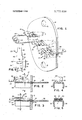
- FIG. 1 is an isometric view, partly in section, showing a terminal assembly including a plurality of the wire connectors of the invention
- FIGS. 2 and 3 are, respectively, side sectional views of a wire connector of FIG. 1 in open and clamped positions;
- FIGS. 4 and 5 are, respectively, cross sectional views of the wire connectors of FIGS. 2 and 3;
- FIG. 6 is a projected view of a wire connector of FIG. 1.
- FIG. 1 a terminal assembly comprising a terminal board 12 of flat sheet insulating material having a plurality of slots 14 therein and a plurality of electric wire connectors 17, 18 and 19 mounted on said board and extending through said slots.
- Board 12 is also provided with two holes 16 for attaching it to a suitable mounting structure.
- connectors 17, 18 and 19 are formed from flat stock of readily bendable sheet metal and are shown in projected, unbent configuration 20 in FIG. 6.
- Each such connector has a flat base 22 having bent perpendicularly out of the plane thereof on one side thereof a pair of spaced, opposed, generally flat clamping tabs 24, 28 and on the opposite side thereof a pair of side extensions 32, 34 at the sides thereof between said clamping tabs.
- the side extensions 32, 34 extend beyond clamping tab 24 in a direction perpendicular thereto and are interconnected in the plane of base 22 to provide an end extension including an electrical connecting member 36 extending through slots 14.
- the end extension has mounting tabs 40 for mounting connectors 17, 18 and 19 on terminal board 12 with their connecting members on one side of said terminal board and the remainder of said connector on the opposite side of said terminal board.
- Clamping tabs 24, 28 each have a pair of wire receiving apertures closely adjacent to the plane of base 22 generally tangential thereto, apertures 23 and 25 in tab 24 and apertures 27 and 29 in tab 28, with said base having a portion 21 extending between apertures in opposite tabs. Furthermore, the apertures in opposite tabs, for example aperture 27 in tab 28 and aperture 23 in tab 24, are aligned with one another for the insertion of a wire 30 (FIGS. 2 and 4) thereinto to be gripped and clamped between said tabs and base portion 21 upon bending of said tabs toward one another into substantial parallelism with said base portion (FIGS. 3 and 5), as shown with respect to connectors 18 and 19 in FIG. I. It is a particularly important characteristic of the invention that when the clamping tabs are bent into parallelism with the base portion, the apertures therein are deformed from a generally circular to an oval configuration, with the edges of the apertures gripping the wire very tightly.
- FIG. 1 A typical resistance wire assembly is shown in FIG. 1 wherein a resistance wire coil element 44 extends between independent connectors 18 and 19 mounted on terminal board 12 with its opposite end wires 30 gripped and clamped between the tabs and the base portion with the tabs bent toward one another into substantial parallelism with the base portion.
- An electric wire connector formed of readily bendable sheet metal, comprising a flat base having bent out of the plane thereof on one side a pair of spaced, opposed, generally flat clamping tabs said tabs each having at least one wire receiving aperture closely adjacent to said base with said base having a portion extending between said apertures in opposite tabs and having ,side extensions at the sides thereof between said tabs, said side extensions being bent out of the plane of said base on the side thereof opposite said tabs said apertures in opposite tabs being positioned with respect to one another for the insertion of a wire thereinto to be gripped and clamped between said tabs and said base portion upon bending of said tabs toward one another into substantial parallelism with said base portion.
- An electric wire connector formed of readily bendable sheet metal, comprising a flat base having bent out of the plane thereof on one side a pair of spaced, opposed, generally flat clamping tabs said tabs each having at least one wire receiving aperture closely adjacent to said base with said base having a portion extending between said apertures in opposite tabs and having side extensions at the sides thereof between said tabs said side extensions extending beyond at least one of said tabs in a direction perpendicular thereto and are interconnected in the plane of said base to provide an end extension said apertures in opposite tabs being positioned with respect to one another for the insertion of a wire thereinto to be gripped and clamped between said tabs and said base portion upon bending of said tabs toward one another into substantial parallelism with said base portion.
- An electric wire connector formed of readily bendable sheet metal comprising a flat base having bent perpendicularly out of the plane thereof on one side thereof a pair of spaced, opposed, generally flat clamping tabs and on the opposite side thereof a pair of side extensions at the sides thereof between said clamping tabs said side extensions extending beyond one of said clamping tabs in a direction perpendicular thereto and being interconnected in the plane of said base to provide an end extension said tabs each having at least one wire receiving aperture closely adjacent to said base with said base having a portion extending between said apertures in opposite tabs said apertures in opposite tabs being positioned with respect to one another for the insertion of a wire there-into to be gripped and clamped between said tabs and said base portion upon bending of said tabs toward one another into substantial parallelism with said base portion.
- a connector as claimed in claim 5 wherein said end extension is provided with terminal board mounting means for mounting said connector on a terminal board extending in a plane parallel to said tabs and includes an electrical connecting member extending beyond said terminal board mounting means.
- a terminal assembly comprising a terminal board of flat sheet insulating material having a plurality of slots therein and a plurality of electric wire connectors mounted on said board and extending through said slots said connectors being formed of readily bendable sheet metal and comprising a flat base having bent perpendicularly out of the plane thereof on one side thereof a pair of spaced, opposed, generally flat clamping tabs and on the opposite side thereof a pair of side extensions at the sides thereof between said clamping tabs said side extensions extending beyond one of said clamping tabs in a direction perpendicular thereto and being interconnected in the plane of said base to provide an end extension said end extension including an electrical connecting member extending through said slots and having mounting means for mounting said connectors on said terminal board with their electrical connecting members on one side of said terminal board and the remainder of said connector on the opposite side of said terminal board said tabs each having at least one wire receiving aperture closely adjacent said base with said base having a portion extending between said apertures in opposite tabs said apertures in opposite tabs being positioned with respect to one another for
Landscapes
- Multi-Conductor Connections (AREA)
Abstract
A terminal assembly comprising a terminal board of flat sheet insulating material with a plurality of metallic electric wire connectors mounted thereon having on one pair of opposite sides a pair of spaced, opposed, generally flat clamping tabs and on the other pair of opposite sides a pair of side extensions interconnected to provide an end extension including an electrical connecting member. The tabs each have at least one wire receiving aperture closely adjacent the base which has a portion extending between the apertures in opposite tabs. The apertures in opposite tabs are aligned with one another for the insertion of a wire thereinto to be gripped and clamped between the tabs and the base portion upon bending of the tabs toward one another into substantial parallelism with the base portion.
Description
United States Patent n91 Schoelles [111 3,772,638 [451 Nov. 13, 1973 WIRE CONNECTOR [73] Assignee: Ark-Les Switch Corporation,
V Watertown, Mass.
22 Filed: July 13, 1972 21 Appl. No.: 271,285
[52] U.S. Cl. 339/198 R, 339/220 R, 339/250,
339/276 R [51] Int. Cl H011 9/00 [58] Field of Search 339/198 R, 198 C,
339/198 E, 198 G, 198 GA, 198 11,198 J, 198 K, 198 S, 198 P, 95 R, 95 D, 96, 97 R, 97 C, 97 P, 220 R, 220 A, 220 C, 220 L, 220 T, 248, 250, 223 R, 276 R, 276 A, 276 C, 276 D, 276 E, 276 F, 276 R, 276 S, 276 T, 277 R, 277 C; 24/115 A, 123 W, 129 W, 265
[56] References Cited UNITED STATES PATENTS 2,583,530 H1952 Hasselbohm 339/95 R 3,702,456 11/1972 Patton 339/198 H 12/1971 Deutsch 339/276 R 3/1929 Roberts 339/276 R X Primary ExaminerMarvin A. Champion Assistant Examiner--Robert A. Hafer Attorney-Martin Kirkpatrick [57] ABSTRACT A terminal assembly comprising a terminal board of flat sheet insulating material with a plurality of metallic electric wire connectors mounted thereon having on one pair of opposite sides a pair of spaced, opposed, generally flat clamping tabs and on the other pair of opposite sides a pair of side extensions interconnected to provide an end extension including an electrical connecting member. The tabs each have at least one wire receiving aperture closely adjacent the base which has a portion extending between the apertures in opposite tabs. The apertures in opposite tabs are aligned with one another for the insertion of a wire thereinto to be gripped and clamped between the tabs and the base portion upon bending of the tabs toward one another into substantial parallelism with the base pOrtlOn.
8 Claims, 6 Drawing Figures WIRE CONNECTOR This invention relates to electric wire connectors and terminal assemblies thereof.
The provision of satisfactory electric wire connectors and assemblies thereof has been a problem especially in connection with the mounting of bare resistance wire elements. This is due to the intermittent heating and cooling of such elements, with its resulting expansion and contraction, tending to loosen the elements with respect to their connectors, producing an unreliable electrical connection therebetween.
Accordingly, it is a major object of the present invention to remedy this deficiency in a practical and economical manner.
This is accomplished in the present invention by providing an electric wire connector, formed of readily bendable sheet metal, comprising a flat base having bent, preferably perpendicularly, out of the plane thereof on one pair of opposite sides a pair of spaced,
opposed, generally flat clamping tabs each having at 7 least one and preferably at least two wire receiving apertures closely adjacent to the base, with the base having a portion extending between the apertures in opposite tabs. The apertures in opposite tabs are positioned with respect to one another for the insertion of a wire thereinto to be gripped and clamped between the tabs and the base portion upon bending of the tabs toward one another into substantial parallelism with the base portion. Preferably, the base has side extensions at the sides thereof between the tabs bent perpendicularly out of the plane of the base on the side thereof opposite the tabs, said side extensions extending beyond at least one and preferably both of the tabs in a direction perpendicular thereto and being interconnected in the plane of the base to provide an end extension which is provided with terminal board mounting means for mounting the connector on a terminal board of flat sheet insulating material having a plurality of slots therein, extending in a plane parallel to the tabs. Preferably, too, the end extension includes an electrical connecting member extending beyond the terminal board mounting means.
For the purpose of more fully explaining further objects and features of the invention, reference is now made to the following detailed description of a preferred embodiment thereof, together with the accompanying drawings, wherein:
FIG. 1 is an isometric view, partly in section, showing a terminal assembly including a plurality of the wire connectors of the invention;
FIGS. 2 and 3 are, respectively, side sectional views of a wire connector of FIG. 1 in open and clamped positions;
FIGS. 4 and 5 are, respectively, cross sectional views of the wire connectors of FIGS. 2 and 3; and
FIG. 6 is a projected view of a wire connector of FIG. 1.
Referring to the drawings, in FIG. 1 is illustrated a terminal assembly comprising a terminal board 12 of flat sheet insulating material having a plurality of slots 14 therein and a plurality of electric wire connectors 17, 18 and 19 mounted on said board and extending through said slots. Board 12 is also provided with two holes 16 for attaching it to a suitable mounting structure.
According to the invention, connectors 17, 18 and 19 are formed from flat stock of readily bendable sheet metal and are shown in projected, unbent configuration 20 in FIG. 6. Each such connector has a flat base 22 having bent perpendicularly out of the plane thereof on one side thereof a pair of spaced, opposed, generally flat clamping tabs 24, 28 and on the opposite side thereof a pair of side extensions 32, 34 at the sides thereof between said clamping tabs.
The side extensions 32, 34 extend beyond clamping tab 24 in a direction perpendicular thereto and are interconnected in the plane of base 22 to provide an end extension including an electrical connecting member 36 extending through slots 14. The end extension has mounting tabs 40 for mounting connectors 17, 18 and 19 on terminal board 12 with their connecting members on one side of said terminal board and the remainder of said connector on the opposite side of said terminal board.
Clamping tabs 24, 28 each have a pair of wire receiving apertures closely adjacent to the plane of base 22 generally tangential thereto, apertures 23 and 25 in tab 24 and apertures 27 and 29 in tab 28, with said base having a portion 21 extending between apertures in opposite tabs. Furthermore, the apertures in opposite tabs, for example aperture 27 in tab 28 and aperture 23 in tab 24, are aligned with one another for the insertion of a wire 30 (FIGS. 2 and 4) thereinto to be gripped and clamped between said tabs and base portion 21 upon bending of said tabs toward one another into substantial parallelism with said base portion (FIGS. 3 and 5), as shown with respect to connectors 18 and 19 in FIG. I. It is a particularly important characteristic of the invention that when the clamping tabs are bent into parallelism with the base portion, the apertures therein are deformed from a generally circular to an oval configuration, with the edges of the apertures gripping the wire very tightly.
A typical resistance wire assembly is shown in FIG. 1 wherein a resistance wire coil element 44 extends between independent connectors 18 and 19 mounted on terminal board 12 with its opposite end wires 30 gripped and clamped between the tabs and the base portion with the tabs bent toward one another into substantial parallelism with the base portion.
What is claimed is: 1. An electric wire connector formed of readily bendable sheet metal, comprising a flat base having bent out of the plane thereof on one side a pair of spaced, opposed, generally flat clamping tabs said tabs each having at least one wire receiving aperture closely adjacent to said base with said base having a portion extending between said apertures in opposite tabs and having ,side extensions at the sides thereof between said tabs, said side extensions being bent out of the plane of said base on the side thereof opposite said tabs said apertures in opposite tabs being positioned with respect to one another for the insertion of a wire thereinto to be gripped and clamped between said tabs and said base portion upon bending of said tabs toward one another into substantial parallelism with said base portion. 2. An electric wire connector formed of readily bendable sheet metal, comprising a flat base having bent out of the plane thereof on one side a pair of spaced, opposed, generally flat clamping tabs said tabs each having at least one wire receiving aperture closely adjacent to said base with said base having a portion extending between said apertures in opposite tabs and having side extensions at the sides thereof between said tabs said side extensions extending beyond at least one of said tabs in a direction perpendicular thereto and are interconnected in the plane of said base to provide an end extension said apertures in opposite tabs being positioned with respect to one another for the insertion of a wire thereinto to be gripped and clamped between said tabs and said base portion upon bending of said tabs toward one another into substantial parallelism with said base portion.
3. A connector as claimed in claim 2 wherein said end extension is provided with terminal board mounting means for mounting said connector on a terminal board extending in a plane parallel to said tabs.
4. A connector as claimed in claim 3 wherein said end extension includes an electrical connecting member extending beyond said terminal board mounting means.
5. An electric wire connector formed of readily bendable sheet metal comprising a flat base having bent perpendicularly out of the plane thereof on one side thereof a pair of spaced, opposed, generally flat clamping tabs and on the opposite side thereof a pair of side extensions at the sides thereof between said clamping tabs said side extensions extending beyond one of said clamping tabs in a direction perpendicular thereto and being interconnected in the plane of said base to provide an end extension said tabs each having at least one wire receiving aperture closely adjacent to said base with said base having a portion extending between said apertures in opposite tabs said apertures in opposite tabs being positioned with respect to one another for the insertion of a wire there-into to be gripped and clamped between said tabs and said base portion upon bending of said tabs toward one another into substantial parallelism with said base portion.
6. A connector as claimed in claim 5 wherein said end extension is provided with terminal board mounting means for mounting said connector on a terminal board extending in a plane parallel to said tabs and includes an electrical connecting member extending beyond said terminal board mounting means.
7. A terminal assembly comprising a terminal board of flat sheet insulating material having a plurality of slots therein and a plurality of electric wire connectors mounted on said board and extending through said slots said connectors being formed of readily bendable sheet metal and comprising a flat base having bent perpendicularly out of the plane thereof on one side thereof a pair of spaced, opposed, generally flat clamping tabs and on the opposite side thereof a pair of side extensions at the sides thereof between said clamping tabs said side extensions extending beyond one of said clamping tabs in a direction perpendicular thereto and being interconnected in the plane of said base to provide an end extension said end extension including an electrical connecting member extending through said slots and having mounting means for mounting said connectors on said terminal board with their electrical connecting members on one side of said terminal board and the remainder of said connector on the opposite side of said terminal board said tabs each having at least one wire receiving aperture closely adjacent said base with said base having a portion extending between said apertures in opposite tabs said apertures in opposite tabs being positioned with respect to one another for the insertion of a wire thereinto to be gripped and clamped between said tabs and said base portion upon bending of said tabs toward one another into substantial parallelism with said base portion.
8. A terminal assembly as claimed in claim 7, further including a resistance wire element extending between independent connectors mounted on said terminal board said resistance wire having its opposite ends gripped and clamped between said tabs and said base portion with said tabs bent toward one another into substantial parallelism with said base portion.
Claims (8)
1. An electric wire connector formed of readily bendable sheet metal, comprising a flat base having bent out of the plane thereof on one side a pair of spaced, opposed, generally flat clamping tabs said tabs each having at least one wire receiving aperture closely adjacent to said base with said base having a portion extending between said apertures in opposite tabs and having side extensions at the sides thereof between said tabs, said side extensions being bent out of the plane of said base on the side thereof opposite said tabs said apertures in opposite tabs being positioned with respect to one another for the insertion of a wire thereinto to be gripped and clamped between said tabs and said base portion upon bending of said tabs toward one another into substantial parallelism with said base portion.
2. An electric wire connector formed of readily bendable sheet metal, comprising a flat base having bent out of the planE thereof on one side a pair of spaced, opposed, generally flat clamping tabs said tabs each having at least one wire receiving aperture closely adjacent to said base with said base having a portion extending between said apertures in opposite tabs and having side extensions at the sides thereof between said tabs said side extensions extending beyond at least one of said tabs in a direction perpendicular thereto and are interconnected in the plane of said base to provide an end extension said apertures in opposite tabs being positioned with respect to one another for the insertion of a wire thereinto to be gripped and clamped between said tabs and said base portion upon bending of said tabs toward one another into substantial parallelism with said base portion.
3. A connector as claimed in claim 2 wherein said end extension is provided with terminal board mounting means for mounting said connector on a terminal board extending in a plane parallel to said tabs.
4. A connector as claimed in claim 3 wherein said end extension includes an electrical connecting member extending beyond said terminal board mounting means.
5. An electric wire connector formed of readily bendable sheet metal comprising a flat base having bent perpendicularly out of the plane thereof on one side thereof a pair of spaced, opposed, generally flat clamping tabs and on the opposite side thereof a pair of side extensions at the sides thereof between said clamping tabs said side extensions extending beyond one of said clamping tabs in a direction perpendicular thereto and being interconnected in the plane of said base to provide an end extension said tabs each having at least one wire receiving aperture closely adjacent to said base with said base having a portion extending between said apertures in opposite tabs said apertures in opposite tabs being positioned with respect to one another for the insertion of a wire there-into to be gripped and clamped between said tabs and said base portion upon bending of said tabs toward one another into substantial parallelism with said base portion.
6. A connector as claimed in claim 5 wherein said end extension is provided with terminal board mounting means for mounting said connector on a terminal board extending in a plane parallel to said tabs and includes an electrical connecting member extending beyond said terminal board mounting means.
7. A terminal assembly comprising a terminal board of flat sheet insulating material having a plurality of slots therein and a plurality of electric wire connectors mounted on said board and extending through said slots said connectors being formed of readily bendable sheet metal and comprising a flat base having bent perpendicularly out of the plane thereof on one side thereof a pair of spaced, opposed, generally flat clamping tabs and on the opposite side thereof a pair of side extensions at the sides thereof between said clamping tabs said side extensions extending beyond one of said clamping tabs in a direction perpendicular thereto and being interconnected in the plane of said base to provide an end extension said end extension including an electrical connecting member extending through said slots and having mounting means for mounting said connectors on said terminal board with their electrical connecting members on one side of said terminal board and the remainder of said connector on the opposite side of said terminal board said tabs each having at least one wire receiving aperture closely adjacent said base with said base having a portion extending between said apertures in opposite tabs said apertures in opposite tabs being positioned with respect to one another for the insertion of a wire thereinto to be gripped and clamped between said tabs and said base portion upon bending of said tabs toward one another into substantial parallelism with said base portion.
8. A terminal assembly as claimed in claim 7, further including a resistance wire element extending between independent connectors mounted on said terminal board said resistance wire having its opposite ends gripped and clamped between said tabs and said base portion with said tabs bent toward one another into substantial parallelism with said base portion.
Applications Claiming Priority (1)
| Application Number | Priority Date | Filing Date | Title |
|---|---|---|---|
| US27128572A | 1972-07-13 | 1972-07-13 |
Publications (1)
| Publication Number | Publication Date |
|---|---|
| US3772638A true US3772638A (en) | 1973-11-13 |
Family
ID=23034933
Family Applications (1)
| Application Number | Title | Priority Date | Filing Date |
|---|---|---|---|
| US00271285A Expired - Lifetime US3772638A (en) | 1972-07-13 | 1972-07-13 | Wire connector |
Country Status (1)
| Country | Link |
|---|---|
| US (1) | US3772638A (en) |
Cited By (8)
| Publication number | Priority date | Publication date | Assignee | Title |
|---|---|---|---|---|
| US4073561A (en) * | 1976-11-18 | 1978-02-14 | Baranowski Conrad J | Method for forming a heat sink and connector device and the product thereof |
| GB2184614A (en) * | 1985-12-24 | 1987-06-24 | Kun Shan Chen | Attaching a wire to an electrical terminal |
| EP0623971A3 (en) * | 1993-05-07 | 1995-01-11 | Irca Spa | Improved method for the connection of heater elements. |
| US5811470A (en) * | 1996-05-06 | 1998-09-22 | Albemarle Corporation | Flame retardant styrenic polymers |
| US6373720B1 (en) * | 1998-04-22 | 2002-04-16 | Alcatel | Module with electronic components |
| CN102811508A (en) * | 2012-08-01 | 2012-12-05 | 杭州热威机电有限公司 | Wiring piece fixing structure |
| CN109168202A (en) * | 2018-08-21 | 2019-01-08 | 宿州国威热敏新材料有限公司 | A kind of ptc heater part and the electric appliance containing the ptc heater part |
| CN116505692A (en) * | 2022-01-18 | 2023-07-28 | 宁波高悦电机技术有限公司 | A terminal composite terminal board and stator |
Citations (4)
| Publication number | Priority date | Publication date | Assignee | Title |
|---|---|---|---|---|
| US1706412A (en) * | 1924-02-29 | 1929-03-26 | Pittsburgh Transformer Co | Terminal for conductors |
| US2583530A (en) * | 1947-01-30 | 1952-01-29 | Ericsson Telefon Ab L M | Electrical connecting terminal strap |
| US3629811A (en) * | 1970-04-06 | 1971-12-21 | Clare & Co C P | Terminal for assembly into a terminal block |
| US3702456A (en) * | 1971-04-07 | 1972-11-07 | Amp Inc | Electrical terminal block for interconnecting a plurality of conductors |
-
1972
- 1972-07-13 US US00271285A patent/US3772638A/en not_active Expired - Lifetime
Patent Citations (4)
| Publication number | Priority date | Publication date | Assignee | Title |
|---|---|---|---|---|
| US1706412A (en) * | 1924-02-29 | 1929-03-26 | Pittsburgh Transformer Co | Terminal for conductors |
| US2583530A (en) * | 1947-01-30 | 1952-01-29 | Ericsson Telefon Ab L M | Electrical connecting terminal strap |
| US3629811A (en) * | 1970-04-06 | 1971-12-21 | Clare & Co C P | Terminal for assembly into a terminal block |
| US3702456A (en) * | 1971-04-07 | 1972-11-07 | Amp Inc | Electrical terminal block for interconnecting a plurality of conductors |
Cited By (9)
| Publication number | Priority date | Publication date | Assignee | Title |
|---|---|---|---|---|
| US4073561A (en) * | 1976-11-18 | 1978-02-14 | Baranowski Conrad J | Method for forming a heat sink and connector device and the product thereof |
| GB2184614A (en) * | 1985-12-24 | 1987-06-24 | Kun Shan Chen | Attaching a wire to an electrical terminal |
| EP0623971A3 (en) * | 1993-05-07 | 1995-01-11 | Irca Spa | Improved method for the connection of heater elements. |
| US5811470A (en) * | 1996-05-06 | 1998-09-22 | Albemarle Corporation | Flame retardant styrenic polymers |
| US6373720B1 (en) * | 1998-04-22 | 2002-04-16 | Alcatel | Module with electronic components |
| CN102811508A (en) * | 2012-08-01 | 2012-12-05 | 杭州热威机电有限公司 | Wiring piece fixing structure |
| CN109168202A (en) * | 2018-08-21 | 2019-01-08 | 宿州国威热敏新材料有限公司 | A kind of ptc heater part and the electric appliance containing the ptc heater part |
| CN109168202B (en) * | 2018-08-21 | 2024-05-24 | 宿州国威热敏新材料有限公司 | A PTC heating device and an electrical appliance containing the PTC heating device |
| CN116505692A (en) * | 2022-01-18 | 2023-07-28 | 宁波高悦电机技术有限公司 | A terminal composite terminal board and stator |
Similar Documents
| Publication | Publication Date | Title |
|---|---|---|
| US5297966A (en) | Mounting bracket for an electrical connector | |
| US3845455A (en) | Tubular conductor-in-slot connecting device | |
| US4322120A (en) | Plug-in connector with improved spring contact | |
| US3891293A (en) | Flat cable terminating | |
| US5697815A (en) | Electrical connectors | |
| US3731254A (en) | Jumper for interconnecting dual-in-line sockets | |
| US4484791A (en) | Connector for multiconductor flat insulated cable | |
| US4655522A (en) | Electrical terminal receptacle | |
| EP1368862B1 (en) | Electrical connector for power conductors | |
| US3585570A (en) | Electrical terminal assembly | |
| US4029377A (en) | Push-on bus bar | |
| US3496521A (en) | Safety contact terminal for electric wires | |
| US3680032A (en) | Printed circuit board connector assembly | |
| JPH03226976A (en) | Electric connector and contact for use with electric connector | |
| US3772638A (en) | Wire connector | |
| JPS643031B2 (en) | ||
| US3768062A (en) | Terminal for flexible circuits | |
| JPH1050375A (en) | Through and branch contact for plug-in connector or terminal | |
| US3654594A (en) | Crimp type terminal | |
| US3611275A (en) | Thin film clip-lead device | |
| US3336561A (en) | Electrical connection means | |
| US4511200A (en) | Electrical connector having handle-mounted bifurcated resilient pin-engaging electrical plate | |
| US3727170A (en) | Flat cable connector | |
| GB2103434A (en) | Electrical connector | |
| US6241549B1 (en) | Pressure-contact terminal and electric connection box containing pressure-contact terminals |