EP0623841A1 - Automatic processors - Google Patents
Automatic processors Download PDFInfo
- Publication number
- EP0623841A1 EP0623841A1 EP94201187A EP94201187A EP0623841A1 EP 0623841 A1 EP0623841 A1 EP 0623841A1 EP 94201187 A EP94201187 A EP 94201187A EP 94201187 A EP94201187 A EP 94201187A EP 0623841 A1 EP0623841 A1 EP 0623841A1
- Authority
- EP
- European Patent Office
- Prior art keywords
- processing
- channel
- module
- solution
- modules
- Prior art date
- Legal status (The legal status is an assumption and is not a legal conclusion. Google has not performed a legal analysis and makes no representation as to the accuracy of the status listed.)
- Granted
Links
Images


Classifications
-
- G—PHYSICS
- G03—PHOTOGRAPHY; CINEMATOGRAPHY; ANALOGOUS TECHNIQUES USING WAVES OTHER THAN OPTICAL WAVES; ELECTROGRAPHY; HOLOGRAPHY
- G03D—APPARATUS FOR PROCESSING EXPOSED PHOTOGRAPHIC MATERIALS; ACCESSORIES THEREFOR
- G03D3/00—Liquid processing apparatus involving immersion; Washing apparatus involving immersion
- G03D3/08—Liquid processing apparatus involving immersion; Washing apparatus involving immersion having progressive mechanical movement of exposed material
- G03D3/13—Liquid processing apparatus involving immersion; Washing apparatus involving immersion having progressive mechanical movement of exposed material for long films or prints in the shape of strips, e.g. fed by roller assembly
- G03D3/132—Liquid processing apparatus involving immersion; Washing apparatus involving immersion having progressive mechanical movement of exposed material for long films or prints in the shape of strips, e.g. fed by roller assembly fed by roller assembly
-
- G—PHYSICS
- G03—PHOTOGRAPHY; CINEMATOGRAPHY; ANALOGOUS TECHNIQUES USING WAVES OTHER THAN OPTICAL WAVES; ELECTROGRAPHY; HOLOGRAPHY
- G03D—APPARATUS FOR PROCESSING EXPOSED PHOTOGRAPHIC MATERIALS; ACCESSORIES THEREFOR
- G03D3/00—Liquid processing apparatus involving immersion; Washing apparatus involving immersion
- G03D3/02—Details of liquid circulation
- G03D3/06—Liquid supply; Liquid circulation outside tanks
-
- G—PHYSICS
- G03—PHOTOGRAPHY; CINEMATOGRAPHY; ANALOGOUS TECHNIQUES USING WAVES OTHER THAN OPTICAL WAVES; ELECTROGRAPHY; HOLOGRAPHY
- G03D—APPARATUS FOR PROCESSING EXPOSED PHOTOGRAPHIC MATERIALS; ACCESSORIES THEREFOR
- G03D5/00—Liquid processing apparatus in which no immersion is effected; Washing apparatus in which no immersion is effected
- G03D5/04—Liquid processing apparatus in which no immersion is effected; Washing apparatus in which no immersion is effected using liquid sprays
Definitions
- the invention relates to automatic processors and is more particularly concerned with the vertical and horizontal positioning and coupling of processing modules forming such processors.
- the processing of photosensitive material involves a series of steps such as developing, bleaching, fixing, washing, and drying. These steps lend themselves to mechanization by conveying a continuous web of film or cut sheets of film or photographic paper sequentially through a series of stations or tanks, each one containing a different processing liquid appropriate to the process step at that station.
- a large photofinishing apparatus utilizes tanks which contain approximately 100 liters of each processing solution.
- a small photofinishing apparatus or microlab utilizes tanks which may contain less than 10 liters of processing solution.
- apparatus for processing photosensitive materials comprising:- at least one processing module each comprising a container, at least one processing assembly placed in the container and forming a processing channel through which a processing solution flows, each processing assembly having at least one discharge opening for introducing processing solution into the processing channel, the processing channel comprising at least 40% of the total volume of processing solution available for the processing module and has a thickness equal to or less than about 100 times the thickness of the photosensitive material to be processed in the processing channel; and recirculating means for recirculating the processing solution from the small volume provided in the processing module directly to each discharge opening; wherein at least two processing modules are interconnected so that photosensitive material can be passed from one module to the next.
- the apparatus may comprise at least two processing modules horizontally coupled together to form a multi-step processor.
- the processing modules (10) may be vertically stacked.
- the processing modules may be both horizontally coupled and vertically stacked to form a multi-step processor having a desired configuration dictated by the space available.
- the arrangement of processing modules in accordance with the present invention allows one to add or subtract processing modules in either a horizontal or a vertical direction to solve the space constraints and the rigidity of prior photographic processor designs.
- a vertical arrangement of processing modules requires a much smaller space than a horizontal arrangement of processing modules and allows for larger more complex processes without the addition of any space.
- the ability to configure a photographic processor differently by adding or eliminating a module or the ability to combine modules horizontally or vertically allows one to position the processor more conveniently in the site space taking better advantage of the shape of the site space. Thus, permitting the photographic processor to be used in more locations.
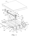
- the reference character 10 represents a processing module, which may stand alone or be easily combined or adjoined with other processing modules 10 to form a continuous low volume unit for processing photosensitive materials.
- Processing module 10 includes: a container 11; an upturned entrance channel 100 (described in the description of Figure 2); an entry transport roller assembly 12; transport roller assemblies 13; an exit transport roller assembly 15; an upturned exit channel 101 (described in the description of Figure 2); high impingement slot nozzles 17a, 17b and 17c; a drive 16 and a rotating assembly 18, assembly 18 may be any known means for turning drive 16, i.e., a motor, a gear, a belt, a chain, etc.
- An access hole 61 is provided in container 11. Hole 61 is utilized for the interconnection of modules 10. Assemblies 12, 13 and 15 and slot nozzles 17a, 17b and 17c are positioned within the vicinity of the walls of container 11.
- Drive 16 is connected to roller assemblies 12, 13 and 15 and turning assembly 18 and assembly 16 is used to transmit the motion of assembly 18 to assemblies 12, 13 and 15.
- Roller assemblies 12, 13, and 15, and slot nozzles 17a, 17b and 17c may be easily inserted into or removed from container 11.
- Roller assembly 13 includes: a top roller 22; a bottom roller 23; tension springs 62, which holds top roller 22 in compression with respect to bottom roller 23; a bearing bracket 26; and a channel section 24 having a thin low volume processing channel 25.
- a narrow channel opening 27 ( Figure 2) exists within section 24. Opening 27 on the entrance side of section 24 may be the same size and shape as opening 27 on the exit side of section 24. Opening 27 on the entrance side of section 24 may also be relieved, tapered or larger than the exit side of section 24 to accommodate rigidity variations of various types of photosensitive material 21.
- Channel opening 27 forms a portion of processing channel 25.
- Rollers 22 and 23 may be drive or driven rollers and are connected to bracket 26. Rollers 22 and 23 are rotated by intermeshing gears 28.
- Photosensitive material 21 is transported in either direction A or direction B automatically through processing channel 25 by roller assemblies 12, 13 and 15.
- Photosensitive material 21 may be in a cut sheet or roll format or photosensitive material 21 may be simultaneously in a roll and simultaneously in a cut sheet format.
- Photosensitive material 21 may contain an emulsion on either or both of its surfaces.
- module 10 with its associated recirculation system 60 which is described in the description of Figure 5, will be a stand alone light tight module which is capable of processing photosensitive material, i.e., a monobath.
- a multi-stage continuous processing unit may be formed. The combination of one or more modules 10 will be more fully set forth in the description of Figure 6.
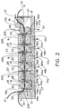
- FIG 2 is a partially sectioned view of module 10 shown in Figure 1.
- Assemblies 12, 13 and 15, nozzles 17a, 17b and 17c and backing plate 9 are designed in a manner to minimize the amount of processing solution which is contained in processing channel 25, vessel 11, recirculation system 60 ( Figure 5) and gaps 49a, 49b, 49c and 49d.
- An upturned channel 100 forms the entrance to processing channel 25.
- an upturned channel 101 forms the exit to processing channel 25.
- Assembly 12 is similar to assembly 13.
- Assembly 12 includes: a top roller 30; a bottom roller 31; tension springs 62 (not shown) which holds top roller 30 to bottom roller 31; a bearing bracket 26; and a channel section 24.
- a portion of narrow processing channel 25 is formed by channel section 24.
- Rollers 30 and 31 may be drive or driven rollers and are connected to bracket 26.
- Assembly 15 is similar to assembly 13, except that assembly 15 has an additional two rollers 130 and 131, which operate in the same manner as rollers 32 and 33.
- Assembly 15 includes: a top roller 32; a bottom roller 33; tension springs 62 (not shown); a top roller 130; a bottom roller 131; a bearing bracket 26; and a channel section 24.
- a portion of narrow processing channel 25 exists within section 24.
- Channel section 24 forms a portion of processing channel 25.
- Rollers 32, 33, 130 and 131 may be drive or driven rollers and are connected to bracket 26.
- Backing plate 9 and slot nozzles 17a, 17b and 17c are affixed to container 11.
- the embodiment shown in Figure 2 will be used when photosensitive material 21 has an emulsion on one of its surfaces.
- the emulsion side of material 21 will face slot nozzles 17a, 17b and 17c.
- Material 21 enters channel 25 between rollers 30 and 31 and moves past backing plate 9 and nozzle 17a.
- material 21 moves between rollers 22 and 23 and moves past backing plates 9 and nozzles 17b and 17c.
- material 21 will move between rollers 32 and 33, and move between rollers 130 and 131 and exit processing channel 25.
- Conduit 48a connects gap 49a, via port 44a to recirculation system 60 via port 44 ( Figure 5), which is more fully described in the description of Figure 5, and conduit 48b connects gap 49b, via port 45a to recirculation system 60 via port 45 ( Figure 5).
- Conduit 48c connects gap 49c, via port 46a to recirculation system 60 via port 46 ( Figure 5) and conduit 48d connects gap 49d, via port 47a to recirculation system 60 via port 47 ( Figure 5).
- Slot nozzle 17a is connected to recirculation system 60 via conduit 50a and inlet port 41a via port 44 ( Figure 5) and slot nozzle 17b is connected to recirculation system 60 via conduit 50b and inlet port 42a via inlet port 42 ( Figure 5).
- Conduit 50c connects nozzle 17c, via inlet port 43a to recirculation system 60 via port 43 ( Figure 5).
- Sensor 52 is connected to container 11 and sensor 52 is used to maintain a processing solution level 235 relative to conduit 51. Excess processing solution may be removed by overflow conduit 51.
- Textured surface 200 is affixed to the surface of backing plate 9 which faces processing channel 25 and to the surface of slot nozzles 17a, 17b and 17c that faces processing channel 25.
- Figure 3 is a partially sectioned view of an alternate embodiment of module 10 of Figure 2 in which material 21 has an emulsion on one surface and nozzles 17d, 17e and 17f are on the top portion of container 11.
- Assemblies 12, 13 and 15, nozzles 17d, 17e and 17f and backing plate 9 are designed in a manner to minimize the amount of processing solution which is contained in processing channel 25 and gaps 49e, 49f, 49g and 49h.
- an upturned channel 100 forms the entrance to processing channel 25.
- an upturned channel 101 forms the exit to processing channel 25.
- Assembly 12 is similar to assembly 13.
- Assembly 12 includes: a top roller 30; a bottom roller 31; tension springs 62 (not shown) which holds top roller 30 in compression with respect to bottom roller 31, a bearing bracket 26; and a channel section 24.
- a portion of narrow channel opening 25 exists within section 24.
- Channel section 24 forms a portion of processing channel 25.
- Rollers 30 and 31 may be drive or driven rollers and are connected to bracket 26.
- Assembly 15 is similar to assembly 13, except that assembly 15 has an additional two rollers 130 and 131 which operate in the same manner as rollers 32 and 33.
- Assembly 15 includes: a top roller 32; a bottom roller 33; a tension spring 62 (not shown); a top roller 130; a bottom roller 131; a bearing bracket 26; and a channel section 24.
- a portion of narrow processing channel 25 exists within section 24.
- Channel section 24 forms a portion of processing channel 25.
- Rollers 32, 33, 130 and 131 may be drive or driven rollers and are connected to bracket 26.
- Backing plate 9 and slot nozzles 17d, 17e and 17f are affixed to container 11.
- the embodiment shown in Figure 3 will be used when photosensitive material 21 has an emulsion on one of its surfaces.
- the emulsion side of material 21 will face slot nozzles 17d, 17e and 17f.
- Material 21 enters channel 25 between rollers 30 and 31 and moves past backing plate 9 and nozzle 17d.
- material 21 moves between rollers 22 and 23 and moves past backing plates 9 and nozzles 17e and 17f.
- material 21 will move between rollers 32 and 33 and move between rollers 130 and 131 and exit processing channel 25.
- Conduit 48e connects gap 49e, via port 44b to recirculation system 60 via port 44 ( Figure 5) and conduit 48f connects gap 49f, via port 45b to recirculation system 60 via port 45 ( Figure 5).
- Conduit 48g connects gap 49g, via port 46b to recirculation system 60 via port 46 ( Figure 5) and conduit 48h connects gap 49h, via port 47b to recirculation system 60 via port 47 ( Figure 5).
- Slot nozzle 17d is connected to recirculation system 60 via conduit 50d and inlet port 41b via inlet 41 ( Figure 5) and slot nozzle 17e is connected to recirculation system 60 via conduit 50e and inlet port 42b via port 42 ( Figure 5).
- Conduit 50f connects nozzle 17f, via inlet port 43b to recirculation system 60 via port 43 ( Figure 5).
- Sensor 52 is connected to container 11 and sensor 52 is used to maintain a processing solution level 235 relative to conduit 51. Excess processing solution may be removed by overflow conduit 51.
- Textured surface 200 is affixed to the surface of backing plate 9 which faces processing channel 25 and to the surface of slot nozzles 17d, 17e and 17f which faces processing channel 25.
- Figure 4 is a partially sectioned view of an alternate embodiment of the processing module 10 shown in Figure 2 in which material 21 has an emulsion on both surfaces and nozzles 17g, 17h and 17i are on the top portion of container 11 facing one emulsion surface of material 21 and nozzles 17j, 17k, and 17L are on the bottom portion of container 11 facing the other emulsion surface of material 21.
- Assemblies 12, 13 and 15, nozzles 17g, 17h, 17i, 17j, 17k and 17L are designed in a manner to minimize the amount of processing solution which is contained in processing channel 25 and gaps 49i, 49j, 49k and 49L.
- an upturned channel 100 forms the entrance to processing channel 25.
- Assembly 12 includes: a top roller 30; a bottom roller 31; tension springs 62 (not shown) which holds top roller 30 in compression with respect to bottom roller 31, a bearing bracket 26; and a channel section 24. A portion of narrow processing channel 25 exists within section 24. Channel section 24 forms a portion of processing channel 25. Rollers 30, 31, 130 and 131 may be drive or driven rollers and are connected to bracket 26. Assembly 15 is similar to assembly 13, except that assembly 15 has an additional two rollers 130 and 131 which operate in the same manner as rollers 32 and 33.
- Assembly 15 includes: a top roller 32; a bottom roller 33; tension springs 62 (not shown); a top roller 130; a bottom roller 131; a bearing bracket 26; and a channel section 24.
- a portion of narrow processing channel 25 exists within section 24.
- Channel section 24 forms a portion of processing channel 25.
- Rollers 32, 33, 130 and 131 may be drive or driven rollers and are connected to bracket 26.
- Slot nozzles 17g, 17h and 17i are affixed to the upper portion of container 11.
- Slot nozzles 17j, 17k and 17L are affixed to the lower portion of container 11.
- the embodiment shown in Figure 4 will be used when photosensitive material 21 has an emulsion on both of its two surfaces.
- One emulsion side of material 21 will face slot nozzles 17g, 17h and 17i and the other emulsion side of material 21 will face slot nozzles 17j, 17k and 17L.
- Material 21 enters channel 25 between rollers 30 and 31 and moves past and nozzles 17g and 17j.
- material 21 moves between rollers 22 and 23 and moves past nozzles 17h, 17k, 17i and 17L.
- material 21 will move between rollers 32 and 33 and move between rollers 130 and 131 and exit processing channel 25.
- Conduit 48i connects gap 49i, via port 44c to recirculation system 60 via port 44 ( Figure 5) and conduit 48j connects gap 49k, via port 45c to recirculation system 60 via port 45 ( Figure 5).
- Conduit 48k connects gap 49L, via port 46c to recirculation system 60 and conduit 48L connects gap 49j, via port 47c to recirculation system 60 via port 47 ( Figure 5).
- Slot nozzle 17g is connected to recirculation system 60 via conduit 50g via port 41 ( Figure 5).
- Slot nozzle 17h is connected to recirculation system 60 via conduit 50h and inlet port 62 via port 42 ( Figure 5).
- Conduit 50i connects nozzle 17i, via inlet port 63 to recirculation system 60 via port 43 ( Figure 5).
- Slot nozzle 17j is connected to recirculation system 60 via conduit 50j and inlet port 41c via port 41 ( Figure 5) and slot nozzle 17k is connected to recirculation system 60 via conduit 50k and inlet port 42c via port 42 ( Figure 5).
- Slot nozzle 17L is connected to recirculation system 60 via conduit 50L and inlet port 43c via port 43 ( Figure 5).
- Sensor 52 is connected to container 11 and sensor 52 is used to maintain a processing solution level 235 relative to conduit 51. Excess processing solution may be removed by overflow conduit 51.
- Material 21 enters upturned channel entrance 100, then passes through channel section 24 of channel 25 between rollers 30 and 31 and moves past nozzles 17g and 17j. Then material 21 moves between rollers 22 and 23 and moves past nozzles 17h and 17k, 17L and 17i. At this point material 21 will move between rollers 32 and 33 and exit processing channel 25.
- Textured surface 200 is affixed to the surface of slot nozzles 17g, 17h, 17i, 17j, 17k and 17L which face processing channel 25.
- slot nozzles 17a, 17b, 17c, 17d, 17e, 17f, 17g, 17h, 17i, 17j, 17k, 17L are described in copending European patent application no. which claims priority from USSN 056649 and USSN 209755 filed on 3 May 1993 and 10 March 1994 respectively and entitled A Slot Impingement for an Automatic Tray Processor and copending European patent application no. which claims priority from USSN 056447 and USSN 209180 filed on 3 May 1993 and 10 March 1994 respectively and entitled Counter Cross Flow for an Automatic Tray Processor .
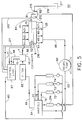
- FIG. 5 is a schematic drawing of the processing solution recirculation system 60 of the apparatus of this invention.
- Module 10 is designed in a manner to minimize the volume of channel 25.
- the outlets 44, 45, 46 and 47 of module 10 are connected to recirculating pump 80 via conduit 85.
- Recirculating pump 80 is connected to manifold 64 via conduit 63 and manifold 64 is coupled to filter 65 via conduit 66.
- Filter 65 is connected to heat exchanger 86 and heat exchanger 86 is connected to channel 25 via conduit 4.
- Control logic 67 is connected to heat exchanger 86 is connected to control logic 67 via wire 68.
- Control logic 67 is connected to heat exchanger 86 via wire 70 and sensor 52 is connected to control logic 86 via wire 71.
- Metering pumps 72, 73 and 74 are respectively connected to manifold 64 via conduits 75, 76 and 77.
- the photographic processing chemicals which comprise the photographic solution are placed in metering pumps 72, 73 and 74.
- Pumps 72, 73 and 74 are used to place the correct amount of chemicals in manifold 64, when photosensitive material 210 sensor senses that material 21 ( Figure 1) is entering channel 25.
- Sensor 210 transmits a signal to pumps 72, 73 and 74 via line 211 and control logic 67.
- Manifold 64 introduces the photographic processing solution into conduit 66.
- the photographic processing solution flows into filter 65 via conduit 66.
- Filter 65 removes contaminants and debris which may be contained in the photographic processing solution. After the photographic processing solution has been filtered, the solution enters heat exchanger 86.
- control logic 67 is the series CN 310 solid state temperature controller manufactured by Omega Engineering, Inc. of 1 Omega Drive, Stamford, Connecticut 06907.
- Logic 67 compares the solution temperature sensed by sensor 8 and the temperature which exchanger 86 transmitted to logic 67 via wire 70.
- Logic 67 will inform exchanger 86 to add or remove heat from the solution.
- logic 67 and heat exchanger 86 modify the temperature of the solution and maintain the solution temperature at the desired level.
- Sensor 52 senses the solution level in channel 25 and transmits the sensed solution level to control logic 67 via wire 71.
- Logic 67 compares the solution level sensed by sensor 52 via wire 71 to the solution level set in logic 67. Logic 67 will inform pumps 72, 73 and 74 via wire 83 to add additional solution if the solution level is low. Once the solution level is at the desired set point control logic 67 will inform pumps 72, 73 and 74 to stop adding additional solution.
- Any excess solution may either be pumped out of module 10 or removed through level drain overflow 84 via conduit 81 into container 82.
- the remaining solution will circulate through channel 25 and reach outlet lines 44, 45,46 and 47. Thereupon, the solution will pass from outlet lines 44, 45, 46 and 47 to conduit line 85 to recirculation pump 80.
- the photographic solution contained in the apparatus of this invention when exposed to the photosensitive material, will reach a seasoned state more rapidly than prior art systems, because the volume of the photographic processing solution is less.
- FIG. 6 shows the coupling of a plurality of processing modules 10 each having a light tight horizontal cover 20 to form a continuous photographic processor.
- Modules 10 may contain the same or similar processing solution to increase the productivity of the processor or perform different processing functions by containing different processing solutions. Any number of modules 10 may be interconnected, only three have been shown for illustrative purposes.
- Drive 16 from each of the modules 10 is interconnected via drive access holes 61, by any known means, i.e., couplings, keyways, belts, chains, hex drives, etc.
- Photosensitive material 21 enters the first module 10 on the left via upturned entrance channel 100 and travels from left module 10 to center module 10 via light tight interconnecting cross over 220 to right module 10 via another cross over 220 and exits this module 10 via upturned exit channel 101.
- Modules 10 are physically connected to each other by any known mechanical fastening means, i.e., screws, snaps, rivets etc. It is obvious to one skilled in the art that photosensitive material 21 (not shown) may travel from right module 10 to left module 10 and is dependent on the chemicals in module 10.
- FIG. 7 shows the integration of a plurality of modules 10 into a single body 102 to form a continuous photographic processor, which contains more than one processing channel 25.
- Each module 10 has a cover 20 and may contain one or more roller assemblies and slot nozzles (not shown) in order to form a continuous photographic processor.
- Modules 10 may contain the same or similar processing solution to increase the productivity of the processor or perform different processing functions by containing different processing solutions. Any number of modules 10 may be interconnected, only three have been shown for illustrative purposes.
- Drive 16 ( Figure 1) from each of the modules 10 is interconnected via drive access hole 61, by any known means, i.e., drives 221 and 222.
- Modules 10 are physically connected to each other by any known mechanical fastening means, i.e., snaps, rivets etc.
- Photosensitive material 21 enters the bottom module via upturned entrance channel 100 and travels from bottom module 10 to middle module 10 via light tight interconnecting cross over 223, through middle module 10 to top module 10 via light tight interconnecting cross over 224 and exits the last module 10 via upturned exit channel 101. It is obvious to one skilled in the art that photosensitive material 21 (not shown) may travel from top module 10 to bottom module 10 and is dependent on the chemicals contained in modules 10.
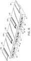
- FIG 8 shows the coupling and vertical stacking of a plurality of modules 10 having a light tight horizontal cover 20 to form a continuous photographic processor.
- Modules 10 may contain the same or similar processing solution to increase the productivity of the processor or perform different processing functions by containing different processing solutions. Any number of modules 10 may be interconnected, only three have been shown for illustrative purposes.
- Drive 16 from two of the modules 10 are interconnected via drive access holes 61, by any known means, i.e., couplings, keyways, belts, chains, hex drives, etc.
- Vertical drive 221, 222 is connected to drive 16 of an appropriate module by any known means such as gears, chains, belts, flexible shafts, couplings, etc.
- Photosensitive material 21 enters the processor arrangement from the left via upturned entrance channel 100 and travels from lower left module 10 to lower right module 10 via light tight interconnecting cross over 220 and then travels from lower right module 10 to top module 10 via light tight cross over 223. Thereupon material 21 exits via upturned exit channel 101.
- Modules 10 are physically connected to each other by any known mechanical fastening means, i.e., screws, snaps, rivets, etc. It is obvious to one skilled in the art that any number of modules 10 may be interconnected in the aforementioned manner.
- a processor made in accordance with the present invention provides a small volume for holding processing solution.
- a narrow processing channel is provided.
- the processing channel 25, for a processor used for photographic paper should have a thickness t equal to or less than about 50 times the thickness of paper being processed, preferably the thickness t is equal to or less than about 10 times the paper thickness.
- the thickness t of the processing channel 25 should be equal to or less than about 100 times the thickness of photosensitive film, preferably, equal to or less than about 18 times the thickness of the photographic film.
- processor made in accordance with the present invention which processes paper having a thickness of about 0.2mm (0.008") would have a channel thickness t of about 2mm (0.080") and a processor which process film having a thickness of about 0.14mm (0.0055”) would have a channel thickness t of about 2.54mm (0.10").
- the total volume of the processing solution within the processing channel 25 and recirculation system 60 is relatively smaller as compared to prior art processors.
- the total amount of processing solution in the entire processing system for a particular module is such that the total volume in the processing channel 25 is at least 40% of the total volume of processing solution in the system.
- the volume of the processing channel 25 is at least about 50% of the total volume of the processing solution in the system. In the particular embodiment illustrated, the volume of the processing channel is about 60% of total volume of the processing solution.
- the amount of processing solution available in the system will vary on the size of the processor, that is, the amount of photosensitive material the processor is capable of processing.
- a processor which processes up to about 0.46m2/min (5ft2/min) of photosensitive material (which generally has a transport speed less than about 1.27m/min (50" per minute) has about 17 liters of processing solution as compared to about 5 liters for a processor made in accordance with the present invention.
- a processor that processes from about 0.46m2/min (5ft2/min) to about 1.39m2/min (15ft2/min) of photosensitive material (which generally has a transport speed from about 1.27m/min (50in/min) to about 3.05m/min (120in/min)) has about 100 liters of processing solution as compared to about 10 liters for a processor made in accordance with the present invention.
- a sump such that a head pressure of approximately 100mm (4") at the exit of the tray to the recirculating pump can be maintained without causing vortexing.
- the sump need only be provided in a localized area adjacent the conduits 48a, 48b, 48c, 48d, 48e, 48f, 48g, 48h, 48i, 48j, 48k, 48L of the tray.
- the nozzles/openings that deliver the processing solution to the processing channel have a configuration in accordance with the following relationship: wherein: F is the flow rate of the solution through the nozzle in gallons per minute; and A is the cross-sectional area of the nozzle provided in square inches.
Abstract
Description
- The invention relates to automatic processors and is more particularly concerned with the vertical and horizontal positioning and coupling of processing modules forming such processors.
- The processing of photosensitive material involves a series of steps such as developing, bleaching, fixing, washing, and drying. These steps lend themselves to mechanization by conveying a continuous web of film or cut sheets of film or photographic paper sequentially through a series of stations or tanks, each one containing a different processing liquid appropriate to the process step at that station.
- There are various sizes of photographic film processing apparatus, i.e., large photofinishing apparatus and microlabs. A large photofinishing apparatus utilizes tanks which contain approximately 100 liters of each processing solution. A small photofinishing apparatus or microlab utilizes tanks which may contain less than 10 liters of processing solution.
- Typically large photofinishing apparatus and microlabs utilize fixed and integrated horizontal and vertical arrangements of racks and tanks. The problem with fixed or integrated photofinishing apparatus and microlabs is that their rack and tank configuration are arranged on a horizontal surface i.e. a floor. This arrangement requires a large amount of floor space.
- In addition the foregoing arrangement of racks and tanks is fixed according to the photographic process steps (developer, bleach, fix and wash) being utilized in the photographic processor. If the site that one wants to utilize for the photographic processor did not contain sufficient horizontal floor space, the photographic processor could not be installed. In the event, an existing photographic processor was placed in a horizontal space and one wanted to modify the processes sequentially performed in the processor by adding additional racks and tanks, one is constrained by the amount of horizontal space available.
- Furthermore, if a rack and tank has to be eliminated from the process sequence, the rack and tank are skipped by the use of a cross over. The space which the rack and tank occupied is not eliminated because the rack and the tank have not been removed. A cross over has been added. Thus, no additional space is gained. Not only does the foregoing create unusable space, it adds excess cross over time to the process step. If the change in process sequence requires the addition of a rack and tank, the inflexibility of current fixed integrated rack and tank designs allow no space or means to add additional racks and tanks.
- It is an object of the present invention to provide automatic processing apparatus which overcomes the disadvantages associated with the prior art.
- In accordance with one aspect of the present invention, there is provided apparatus for processing photosensitive materials, the apparatus comprising:-
at least one processing module each comprising a container, at least one processing assembly placed in the container and forming a processing channel through which a processing solution flows, each processing assembly having at least one discharge opening for introducing processing solution into the processing channel, the processing channel comprising at least 40% of the total volume of processing solution available for the processing module and has a thickness equal to or less than about 100 times the thickness of the photosensitive material to be processed in the processing channel; and
recirculating means for recirculating the processing solution from the small volume provided in the processing module directly to each discharge opening;
wherein at least two processing modules are interconnected so that photosensitive material can be passed from one module to the next. - The apparatus may comprise at least two processing modules horizontally coupled together to form a multi-step processor. Alternatively, the processing modules (10) may be vertically stacked. Additionally, the processing modules may be both horizontally coupled and vertically stacked to form a multi-step processor having a desired configuration dictated by the space available.
- The arrangement of processing modules in accordance with the present invention allows one to add or subtract processing modules in either a horizontal or a vertical direction to solve the space constraints and the rigidity of prior photographic processor designs. A vertical arrangement of processing modules requires a much smaller space than a horizontal arrangement of processing modules and allows for larger more complex processes without the addition of any space.
- Different photosensitive materials require different amounts of time for different parts of the process, i.e., photosensitive materials with thicker gelatins require longer wash times. Thus, the ability to add or subtract modules in the same horizontal space is a real advantage.
- The ability to configure a photographic processor differently by adding or eliminating a module or the ability to combine modules horizontally or vertically allows one to position the processor more conveniently in the site space taking better advantage of the shape of the site space. Thus, permitting the photographic processor to be used in more locations.
- For a better understanding of the present invention, reference will now be made, by way of example only, to the accompanying drawings in which:-
- Figure 1 is a perspective view of a processing module constructed in accordance with the present invention and which forms part of a tray processor;
- Figure 2 is a partially sectioned view of the module shown in Figure 1 illustrating one embodiment of a processing module according to the present invention for processing material having one emulsion surface;
- Figure 3 is a partially sectioned view similar to that shown in Figure 2, but of a second embodiment of a processing module according to the present invention;
- Figure 4 is a partially sectioned view similar to that shown in Figure 2, but of a third embodiment of a processing module according to the present invention for processing material having two emulsion surfaces;
- Figure 5 is a schematic view of a processing solution recirculation system of the apparatus in accordance with the present invention;
- Figure 6 shows a plurality of horizontally aligned modules which are connected together to form a continuous photographic processor in accordance with the present invention;
- Figure 7 shows a plurality of vertically stacked modules which are connected together into a single body to form a continuous photographic processor in accordance with the present invention; and
- Figure 8 shows a combination of horizontal coupling and vertical stacking of modules into a single body to form a continuous photographic processor in accordance with the present invention.
- Referring now to the drawings in detail, and more particularly to Figure 1, the
reference character 10 represents a processing module, which may stand alone or be easily combined or adjoined withother processing modules 10 to form a continuous low volume unit for processing photosensitive materials. -
Processing module 10 includes: acontainer 11; an upturned entrance channel 100 (described in the description of Figure 2); an entrytransport roller assembly 12;transport roller assemblies 13; an exittransport roller assembly 15; an upturned exit channel 101 (described in the description of Figure 2); highimpingement slot nozzles drive 16 and arotating assembly 18,assembly 18 may be any known means forturning drive 16, i.e., a motor, a gear, a belt, a chain, etc. Anaccess hole 61 is provided incontainer 11.Hole 61 is utilized for the interconnection ofmodules 10.Assemblies slot nozzles container 11.Drive 16 is connected toroller assemblies assembly 18 andassembly 16 is used to transmit the motion ofassembly 18 to assemblies 12, 13 and 15. -
Roller assemblies slot nozzles container 11.Roller assembly 13 includes: atop roller 22; abottom roller 23;tension springs 62, which holdstop roller 22 in compression with respect tobottom roller 23; abearing bracket 26; and achannel section 24 having a thin lowvolume processing channel 25. A narrow channel opening 27 (Figure 2) exists withinsection 24. Opening 27 on the entrance side ofsection 24 may be the same size and shape as opening 27 on the exit side ofsection 24. Opening 27 on the entrance side ofsection 24 may also be relieved, tapered or larger than the exit side ofsection 24 to accommodate rigidity variations of various types ofphotosensitive material 21. Channel opening 27 forms a portion ofprocessing channel 25.Rollers bracket 26.Rollers gears 28. -
Photosensitive material 21 is transported in either direction A or direction B automatically throughprocessing channel 25 byroller assemblies Photosensitive material 21 may be in a cut sheet or roll format orphotosensitive material 21 may be simultaneously in a roll and simultaneously in a cut sheet format.Photosensitive material 21 may contain an emulsion on either or both of its surfaces. - When
cover 20 is placed on container 11 a light tight enclosure is formed. Thus,module 10 with its associatedrecirculation system 60, which is described in the description of Figure 5, will be a stand alone light tight module which is capable of processing photosensitive material, i.e., a monobath. When two ormore modules 10 are combined a multi-stage continuous processing unit may be formed. The combination of one ormore modules 10 will be more fully set forth in the description of Figure 6. - Figure 2 is a partially sectioned view of
module 10 shown in Figure 1.Assemblies nozzles backing plate 9 are designed in a manner to minimize the amount of processing solution which is contained inprocessing channel 25,vessel 11, recirculation system 60 (Figure 5) andgaps module 10, anupturned channel 100 forms the entrance to processingchannel 25. At the exit ofmodule 10, anupturned channel 101 forms the exit to processingchannel 25.Assembly 12 is similar toassembly 13.Assembly 12 includes: atop roller 30; abottom roller 31; tension springs 62 (not shown) which holdstop roller 30 tobottom roller 31; abearing bracket 26; and achannel section 24. A portion ofnarrow processing channel 25 is formed bychannel section 24.Rollers bracket 26.Assembly 15 is similar toassembly 13, except thatassembly 15 has an additional tworollers rollers Assembly 15 includes: atop roller 32; abottom roller 33; tension springs 62 (not shown); atop roller 130; abottom roller 131; abearing bracket 26; and achannel section 24. A portion ofnarrow processing channel 25 exists withinsection 24.Channel section 24 forms a portion ofprocessing channel 25.Rollers bracket 26. - Backing
plate 9 andslot nozzles container 11. The embodiment shown in Figure 2 will be used whenphotosensitive material 21 has an emulsion on one of its surfaces. The emulsion side ofmaterial 21 will faceslot nozzles Material 21 enterschannel 25 betweenrollers past backing plate 9 andnozzle 17a. Thenmaterial 21 moves betweenrollers past backing plates 9 andnozzles point material 21 will move betweenrollers rollers exit processing channel 25. -
Conduit 48a connectsgap 49a, viaport 44a torecirculation system 60 via port 44 (Figure 5), which is more fully described in the description of Figure 5, andconduit 48b connectsgap 49b, via port 45a torecirculation system 60 via port 45 (Figure 5).Conduit 48c connectsgap 49c, viaport 46a torecirculation system 60 via port 46 (Figure 5) andconduit 48d connectsgap 49d, via port 47a torecirculation system 60 via port 47 (Figure 5).Slot nozzle 17a is connected torecirculation system 60 viaconduit 50a and inlet port 41a via port 44 (Figure 5) andslot nozzle 17b is connected torecirculation system 60 viaconduit 50b andinlet port 42a via inlet port 42 (Figure 5).Conduit 50c connectsnozzle 17c, via inlet port 43a torecirculation system 60 via port 43 (Figure 5).Sensor 52 is connected tocontainer 11 andsensor 52 is used to maintain aprocessing solution level 235 relative toconduit 51. Excess processing solution may be removed byoverflow conduit 51. -
Textured surface 200 is affixed to the surface ofbacking plate 9 which facesprocessing channel 25 and to the surface ofslot nozzles processing channel 25. - Figure 3 is a partially sectioned view of an alternate embodiment of
module 10 of Figure 2 in whichmaterial 21 has an emulsion on one surface andnozzles container 11.Assemblies nozzles backing plate 9 are designed in a manner to minimize the amount of processing solution which is contained inprocessing channel 25 andgaps module 10, anupturned channel 100 forms the entrance to processingchannel 25. At the exit ofmodule 10, anupturned channel 101 forms the exit to processingchannel 25.Assembly 12 is similar toassembly 13.Assembly 12 includes: atop roller 30; abottom roller 31; tension springs 62 (not shown) which holdstop roller 30 in compression with respect tobottom roller 31, a bearingbracket 26; and achannel section 24. A portion ofnarrow channel opening 25 exists withinsection 24.Channel section 24 forms a portion ofprocessing channel 25.Rollers bracket 26.Assembly 15 is similar toassembly 13, except thatassembly 15 has an additional tworollers rollers Assembly 15 includes: atop roller 32; abottom roller 33; a tension spring 62 (not shown); atop roller 130; abottom roller 131; abearing bracket 26; and achannel section 24. A portion ofnarrow processing channel 25 exists withinsection 24.Channel section 24 forms a portion ofprocessing channel 25.Rollers bracket 26. Thus, it can be seen that a substantially continuous processing channel is provided. - Backing
plate 9 andslot nozzles container 11. The embodiment shown in Figure 3 will be used whenphotosensitive material 21 has an emulsion on one of its surfaces. The emulsion side ofmaterial 21 will faceslot nozzles Material 21 enterschannel 25 betweenrollers past backing plate 9 andnozzle 17d. Thenmaterial 21 moves betweenrollers past backing plates 9 andnozzles point material 21 will move betweenrollers rollers exit processing channel 25. -
Conduit 48e connectsgap 49e, viaport 44b torecirculation system 60 via port 44 (Figure 5) andconduit 48f connectsgap 49f, viaport 45b torecirculation system 60 via port 45 (Figure 5).Conduit 48g connectsgap 49g, viaport 46b torecirculation system 60 via port 46 (Figure 5) andconduit 48h connectsgap 49h, viaport 47b torecirculation system 60 via port 47 (Figure 5).Slot nozzle 17d is connected torecirculation system 60 viaconduit 50d andinlet port 41b via inlet 41 (Figure 5) andslot nozzle 17e is connected torecirculation system 60 viaconduit 50e andinlet port 42b via port 42 (Figure 5).Conduit 50f connectsnozzle 17f, viainlet port 43b torecirculation system 60 via port 43 (Figure 5).Sensor 52 is connected tocontainer 11 andsensor 52 is used to maintain aprocessing solution level 235 relative toconduit 51. Excess processing solution may be removed byoverflow conduit 51. -
Textured surface 200 is affixed to the surface ofbacking plate 9 which facesprocessing channel 25 and to the surface ofslot nozzles processing channel 25. - Figure 4 is a partially sectioned view of an alternate embodiment of the
processing module 10 shown in Figure 2 in whichmaterial 21 has an emulsion on both surfaces andnozzles container 11 facing one emulsion surface ofmaterial 21 andnozzles container 11 facing the other emulsion surface ofmaterial 21.Assemblies nozzles processing channel 25 andgaps module 10, anupturned channel 100 forms the entrance to processingchannel 25. At the exit ofmodule 10, anupturned channel 101 forms the exit to processingchannel 25.Assembly 12 includes: atop roller 30; abottom roller 31; tension springs 62 (not shown) which holdstop roller 30 in compression with respect tobottom roller 31, a bearingbracket 26; and achannel section 24. A portion ofnarrow processing channel 25 exists withinsection 24.Channel section 24 forms a portion ofprocessing channel 25.Rollers bracket 26.Assembly 15 is similar toassembly 13, except thatassembly 15 has an additional tworollers rollers Assembly 15 includes: atop roller 32; abottom roller 33; tension springs 62 (not shown); atop roller 130; abottom roller 131; abearing bracket 26; and achannel section 24. A portion ofnarrow processing channel 25 exists withinsection 24.Channel section 24 forms a portion ofprocessing channel 25.Rollers bracket 26. -
Slot nozzles container 11.Slot nozzles container 11. The embodiment shown in Figure 4 will be used whenphotosensitive material 21 has an emulsion on both of its two surfaces. One emulsion side ofmaterial 21 will faceslot nozzles material 21 will faceslot nozzles Material 21 enterschannel 25 betweenrollers nozzles material 21 moves betweenrollers past nozzles point material 21 will move betweenrollers rollers exit processing channel 25. -
Conduit 48i connectsgap 49i, viaport 44c torecirculation system 60 via port 44 (Figure 5) andconduit 48j connectsgap 49k, viaport 45c torecirculation system 60 via port 45 (Figure 5).Conduit 48k connectsgap 49L, viaport 46c torecirculation system 60 andconduit 48L connectsgap 49j, viaport 47c torecirculation system 60 via port 47 (Figure 5).Slot nozzle 17g is connected torecirculation system 60 viaconduit 50g via port 41 (Figure 5).Slot nozzle 17h is connected torecirculation system 60 viaconduit 50h andinlet port 62 via port 42 (Figure 5).Conduit 50i connectsnozzle 17i, viainlet port 63 torecirculation system 60 via port 43 (Figure 5).Slot nozzle 17j is connected torecirculation system 60 viaconduit 50j andinlet port 41c via port 41 (Figure 5) andslot nozzle 17k is connected torecirculation system 60 via conduit 50k andinlet port 42c via port 42 (Figure 5).Slot nozzle 17L is connected torecirculation system 60 viaconduit 50L andinlet port 43c via port 43 (Figure 5).Sensor 52 is connected tocontainer 11 andsensor 52 is used to maintain aprocessing solution level 235 relative toconduit 51. Excess processing solution may be removed byoverflow conduit 51.Material 21 enters upturnedchannel entrance 100, then passes throughchannel section 24 ofchannel 25 betweenrollers past nozzles material 21 moves betweenrollers past nozzles point material 21 will move betweenrollers exit processing channel 25. -
Textured surface 200 is affixed to the surface ofslot nozzles processing channel 25. - Preferred embodiments of
slot nozzles - Figure 5 is a schematic drawing of the processing
solution recirculation system 60 of the apparatus of this invention.Module 10 is designed in a manner to minimize the volume ofchannel 25. Theoutlets 44, 45, 46 and 47 ofmodule 10 are connected to recirculatingpump 80 viaconduit 85. Recirculatingpump 80 is connected tomanifold 64 viaconduit 63 andmanifold 64 is coupled to filter 65 viaconduit 66.Filter 65 is connected toheat exchanger 86 andheat exchanger 86 is connected to channel 25 viaconduit 4.Control logic 67 is connected toheat exchanger 86 is connected to controllogic 67 viawire 68.Control logic 67 is connected toheat exchanger 86 viawire 70 andsensor 52 is connected to controllogic 86 viawire 71. Metering pumps 72, 73 and 74 are respectively connected tomanifold 64 viaconduits - The photographic processing chemicals which comprise the photographic solution are placed in metering pumps 72, 73 and 74.
Pumps manifold 64, whenphotosensitive material 210 sensor senses that material 21 (Figure 1) is enteringchannel 25.Sensor 210 transmits a signal topumps line 211 and controllogic 67.Manifold 64 introduces the photographic processing solution intoconduit 66. - The photographic processing solution flows into
filter 65 viaconduit 66.Filter 65 removes contaminants and debris which may be contained in the photographic processing solution. After the photographic processing solution has been filtered, the solution entersheat exchanger 86. -
Sensor 52 senses the solution level andsensor 8 senses the temperature of the solution and respectively transmits the solution level and temperature of the solution to controllogic 67 viawires control logic 67 is the series CN 310 solid state temperature controller manufactured by Omega Engineering, Inc. of 1 Omega Drive, Stamford, Connecticut 06907.Logic 67 compares the solution temperature sensed bysensor 8 and the temperature which exchanger 86 transmitted tologic 67 viawire 70.Logic 67 will informexchanger 86 to add or remove heat from the solution. Thus,logic 67 andheat exchanger 86 modify the temperature of the solution and maintain the solution temperature at the desired level. -
Sensor 52 senses the solution level inchannel 25 and transmits the sensed solution level to controllogic 67 viawire 71.Logic 67 compares the solution level sensed bysensor 52 viawire 71 to the solution level set inlogic 67.Logic 67 will informpumps wire 83 to add additional solution if the solution level is low. Once the solution level is at the desired setpoint control logic 67 will informpumps - Any excess solution may either be pumped out of
module 10 or removed throughlevel drain overflow 84 viaconduit 81 intocontainer 82. - At this point the solution enters
module 10 via inlets 41, 42 and 43. Whenmodule 10 contains too much solution the excess solution will be removed byoverflow conduit 51, drainoverflow 84 andconduit 81 and flow intoreservoir 82. The solution level ofreservoir 82 is monitored bysensor 212.Sensor 212 is connected to controllogic 67 vialine 213. Whensensor 212 senses the presence of solution inreservoir 82, a signal is transmitted tologic 67 vialine 213 andlogic 67 enablespump 214. Thereupon, pump 214 pumps solution intomanifold 64. Whensensor 212 does not sense the presence of solution, pump 214 is disabled by the signal transmitted vialine 213 andlogic 67. When solution inreservoir 82 reachesoverflow 215 the solution will be transmitted throughconduit 216 intoreservoir 217. The remaining solution will circulate throughchannel 25 and reachoutlet lines 44, 45,46 and 47. Thereupon, the solution will pass fromoutlet lines 44, 45, 46 and 47 toconduit line 85 torecirculation pump 80. The photographic solution contained in the apparatus of this invention, when exposed to the photosensitive material, will reach a seasoned state more rapidly than prior art systems, because the volume of the photographic processing solution is less. - Figure 6 shows the coupling of a plurality of
processing modules 10 each having a light tighthorizontal cover 20 to form a continuous photographic processor.Modules 10 may contain the same or similar processing solution to increase the productivity of the processor or perform different processing functions by containing different processing solutions. Any number ofmodules 10 may be interconnected, only three have been shown for illustrative purposes. Drive 16 from each of themodules 10 is interconnected via drive access holes 61, by any known means, i.e., couplings, keyways, belts, chains, hex drives, etc. Photosensitive material 21 (not shown) enters thefirst module 10 on the left viaupturned entrance channel 100 and travels fromleft module 10 tocenter module 10 via light tight interconnecting cross over 220 toright module 10 via another cross over 220 and exits thismodule 10 viaupturned exit channel 101.Modules 10 are physically connected to each other by any known mechanical fastening means, i.e., screws, snaps, rivets etc. It is obvious to one skilled in the art that photosensitive material 21 (not shown) may travel fromright module 10 to leftmodule 10 and is dependent on the chemicals inmodule 10. - Figure 7 shows the integration of a plurality of
modules 10 into asingle body 102 to form a continuous photographic processor, which contains more than oneprocessing channel 25. Eachmodule 10 has acover 20 and may contain one or more roller assemblies and slot nozzles (not shown) in order to form a continuous photographic processor.Modules 10 may contain the same or similar processing solution to increase the productivity of the processor or perform different processing functions by containing different processing solutions. Any number ofmodules 10 may be interconnected, only three have been shown for illustrative purposes. Drive 16 (Figure 1) from each of themodules 10 is interconnected viadrive access hole 61, by any known means, i.e., drives 221 and 222.Modules 10 are physically connected to each other by any known mechanical fastening means, i.e., snaps, rivets etc. Photosensitive material 21 (not shown) enters the bottom module viaupturned entrance channel 100 and travels frombottom module 10 tomiddle module 10 via light tight interconnecting cross over 223, throughmiddle module 10 totop module 10 via light tight interconnecting cross over 224 and exits thelast module 10 viaupturned exit channel 101. It is obvious to one skilled in the art that photosensitive material 21 (not shown) may travel fromtop module 10 tobottom module 10 and is dependent on the chemicals contained inmodules 10. - Figure 8 shows the coupling and vertical stacking of a plurality of
modules 10 having a light tighthorizontal cover 20 to form a continuous photographic processor.Modules 10 may contain the same or similar processing solution to increase the productivity of the processor or perform different processing functions by containing different processing solutions. Any number ofmodules 10 may be interconnected, only three have been shown for illustrative purposes. Drive 16 from two of themodules 10 are interconnected via drive access holes 61, by any known means, i.e., couplings, keyways, belts, chains, hex drives, etc.Vertical drive Vertical drive 221 from each material 21 (not shown) may travel fromright module 10 to leftmodule 10 and is dependent on the chemicals inmodule 10. Photosensitive material 21 (not shown) enters the processor arrangement from the left viaupturned entrance channel 100 and travels from lowerleft module 10 to lowerright module 10 via light tight interconnecting cross over 220 and then travels from lowerright module 10 totop module 10 via light tight cross over 223. Thereuponmaterial 21 exits viaupturned exit channel 101.Modules 10 are physically connected to each other by any known mechanical fastening means, i.e., screws, snaps, rivets, etc. It is obvious to one skilled in the art that any number ofmodules 10 may be interconnected in the aforementioned manner. - A processor made in accordance with the present invention provides a small volume for holding processing solution. As a part of limiting the volume of the processing solution, a narrow processing channel is provided. The
processing channel 25, for a processor used for photographic paper, should have a thickness t equal to or less than about 50 times the thickness of paper being processed, preferably the thickness t is equal to or less than about 10 times the paper thickness. In a processor for processing photographic film, the thickness t of theprocessing channel 25 should be equal to or less than about 100 times the thickness of photosensitive film, preferably, equal to or less than about 18 times the thickness of the photographic film. An example of a processor made in accordance with the present invention which processes paper having a thickness of about 0.2mm (0.008") would have a channel thickness t of about 2mm (0.080") and a processor which process film having a thickness of about 0.14mm (0.0055") would have a channel thickness t of about 2.54mm (0.10"). - The total volume of the processing solution within the
processing channel 25 andrecirculation system 60 is relatively smaller as compared to prior art processors. In particular, the total amount of processing solution in the entire processing system for a particular module is such that the total volume in theprocessing channel 25 is at least 40% of the total volume of processing solution in the system. Preferably, the volume of theprocessing channel 25 is at least about 50% of the total volume of the processing solution in the system. In the particular embodiment illustrated, the volume of the processing channel is about 60% of total volume of the processing solution. - Typically the amount of processing solution available in the system will vary on the size of the processor, that is, the amount of photosensitive material the processor is capable of processing. For example, a typical prior art microlab processor, a processor which processes up to about 0.46m²/min (5ft²/min) of photosensitive material (which generally has a transport speed less than about 1.27m/min (50" per minute) has about 17 liters of processing solution as compared to about 5 liters for a processor made in accordance with the present invention. With respect to typical prior art minilabs, a processor that processes from about 0.46m²/min (5ft²/min) to about 1.39m²/min (15ft²/min) of photosensitive material (which generally has a transport speed from about 1.27m/min (50in/min) to about 3.05m/min (120in/min)) has about 100 liters of processing solution as compared to about 10 liters for a processor made in accordance with the present invention. With respect to large prior art lab processors that process up to 4.6m²/min (50ft²/min) of photosensitive material (which generally have transport speeds of about 2.13 to 18m/min (7 to 60ft/min)) typically have from about 150 to 300 liters of processing solution as compared to a range of about 15 to 100 liters for a large processor made in accordance with the present invention. In a minilab size processor made in accordance with the present invention designed to process 1.39m² (15ft²) of photosensitive material per minute would have about 7 liters of processing solution as compared to about 17 liters for a typical prior art processor.
- In certain situations it may be appropriate to provide a sump in the
conduits gaps conduits gaps conduits - In order to provide efficient flow of the processing solution through the nozzles into the processing channel, it is desirable that the nozzles/openings that deliver the processing solution to the processing channel have a configuration in accordance with the following relationship:

wherein:
F is the flow rate of the solution through the nozzle in gallons per minute; and
A is the cross-sectional area of the nozzle provided in square inches. - Providing a nozzle in accordance with the foregoing relationship assures appropriate discharge of the processing solution against the photosensitive material.
- The above specification describes a new and improved apparatus for processing photosensitive materials. It is realized that the above description may indicate to those skilled in the art additional ways in which the principles of this invention may be used without departing from the spirit. It is, therefore, intended that this invention be limited only by the scope of the appended claims.
Claims (10)
- Apparatus for processing photosensitive materials (21), the apparatus comprising:-
at least one processing module (10) each comprising a container (11), at least one processing assembly (9, 17a, 17b, 17c; 17d, 17e, 17f; 17g, 17h, 17i; 17j, 17k, 17L) placed in the container (11) and forming a processing channel (25) through which a processing solution flows, each processing assembly (9, 17a, 17b, 17c; 17d, 17e, 17f; 17g, 17h, 17i; 17j, 17k, 17L) having at least one discharge opening (17a, 17b, 17c; 17d, 17e, 17f; 17g, 17h, 17i; 17j, 17k, 17L) for introducing processing solution into the processing channel (25), the processing channel (25) comprising at least 40% of the total volume of processing solution available for the processing module (10) and has a thickness (t) equal to or less than about 100 times the thickness of the photosensitive material (21) to be processed in the processing channel (25); and
recirculating means (64, 65, 80, 86, 226) for recirculating the processing solution from the small volume provided in the processing module (10) directly to each discharge opening (17a, 17b, 17c; 17d, 17e, 17f; 17g, 17h, 17i; 17j, 17k, 17L);
wherein at least two processing modules (10) are interconnected so that photosensitive material (21) can be passed from one module to the next. - Apparatus according to claim 1, wherein at least two processing modules (10) are horizontally coupled to form a multi-step processor.
- Apparatus according to claim 1, wherein at least two processing modules (10) are vertically stacked to form a multi-step processor.
- Apparatus according to claim 2 or 3, wherein said modules are horizontally coupled and vertically stacked to form a multi-step processor.
- Apparatus according to claim 4, wherein the processing modules (10) are horizontally coupled and vertically stacked to form different types of multi-step processors.
- Apparatus according to any one of claims 2 to 5 further comprising coupling means (220; 223) coupled to each processing module (10) for allowing transport of the photosensitive material (21) from the module to the next.
- Apparatus according to any one of the preceding claims, wherein each processing module (10) further includes at least one transport assembly (12, 13, 15) disposed adjacent each processing assembly (9, 17a, 17b, 17c; 17d, 17e, 17f; 17g, 17h, 17i; 17j, 17k, 17L) for transporting the photosensitive material (21) through the module (10), each transport assembly (12, 13, 15) and processing assembly (9, 17a, 17b, 17c; 17d, 17e, 17f; 17g, 17h, 17i; 17j, 17k, 17L) forming a portion of the processing channel (25).
- Apparatus according to any one of the preceding claims, wherein the processing channel (25) comprises at least 60% of the total volume of the processing solution for the processing module (10).
- Apparatus according to any one of the preceding claims, wherein the processing channel (25) has a thickness (t) equal to or less than about 10 times the thickness of the photosensitive material (21).
- Apparatus according to any one of the preceding claims, wherein each discharge opening (17a, 17b, 17c; 17d, 17e, 17f; 17g, 17h, 17i; 17j, 17k, 17L) has a configuration in accordance with the following relationship:

F is the flow rate of the solution through the nozzle in gallons per minute; and
A is the cross-sectional area of the nozzle provided in square inches.
Applications Claiming Priority (4)
| Application Number | Priority Date | Filing Date | Title |
|---|---|---|---|
| US57131 | 1987-06-01 | ||
| US08/057,131 US5347337A (en) | 1993-05-03 | 1993-05-03 | Vertical and horizontal positioning and coupling of automatic tray processor cells |
| US08/209,754 US5386261A (en) | 1993-05-03 | 1994-03-10 | Vertical and horizontal positioning and coupling of automatic tray processor cells |
| US209754 | 1994-03-10 |
Publications (2)
| Publication Number | Publication Date |
|---|---|
| EP0623841A1 true EP0623841A1 (en) | 1994-11-09 |
| EP0623841B1 EP0623841B1 (en) | 2001-06-13 |
Family
ID=26736107
Family Applications (1)
| Application Number | Title | Priority Date | Filing Date |
|---|---|---|---|
| EP94201187A Expired - Lifetime EP0623841B1 (en) | 1993-05-03 | 1994-04-29 | Automatic processors |
Country Status (7)
| Country | Link |
|---|---|
| US (1) | US5386261A (en) |
| EP (1) | EP0623841B1 (en) |
| JP (2) | JP2928092B2 (en) |
| BR (1) | BR9401679A (en) |
| CA (1) | CA2121082C (en) |
| DE (1) | DE69427425T2 (en) |
| TW (1) | TW233347B (en) |
Cited By (3)
| Publication number | Priority date | Publication date | Assignee | Title |
|---|---|---|---|---|
| EP0725530A2 (en) * | 1995-02-03 | 1996-08-07 | Eastman Kodak Company | Printing and developing apparatus |
| GB2317713A (en) * | 1996-09-30 | 1998-04-01 | Eastman Kodak Co | Photographic processor |
| EP0833200A1 (en) * | 1996-09-30 | 1998-04-01 | Eastman Kodak Company | Photographic processor and method of operation |
Families Citing this family (15)
| Publication number | Priority date | Publication date | Assignee | Title |
|---|---|---|---|---|
| US5660974A (en) | 1994-06-09 | 1997-08-26 | Eastman Kodak Company | Color developer containing hydroxylamine antioxidants |
| US5778272A (en) * | 1996-09-30 | 1998-07-07 | Eastman Kodak Company | Photographic processor and method of operation |
| US5790914A (en) * | 1996-09-30 | 1998-08-04 | Eastman Kodak Company | Photographic processor and method of operation |
| US5701540A (en) * | 1996-09-30 | 1997-12-23 | Eastman Kodak Company | Photographic processor and improved filter assembly |
| US5753111A (en) * | 1996-09-30 | 1998-05-19 | Eastman Kodak Company | Photographic processor and improved filter assembly |
| US5771417A (en) * | 1996-09-30 | 1998-06-23 | Eastman Kodak Company | Photographic processor and method of operation |
| US5761561A (en) * | 1996-09-30 | 1998-06-02 | Eastman Kodak Company | Photographic processor and method of operation |
| US5749017A (en) * | 1996-09-30 | 1998-05-05 | Eastman Kodak Company | Photographic processor and method of operation |
| US5778274A (en) * | 1996-09-30 | 1998-07-07 | Eastman Kodak Company | Photographic processor and method of operation |
| US5822645A (en) * | 1997-04-17 | 1998-10-13 | Eastman Kodak Company | Photographic processor |
| US5822643A (en) * | 1997-04-17 | 1998-10-13 | Eastman Kodak Company | Photographic processor |
| US5903795A (en) * | 1997-05-23 | 1999-05-11 | Eastman Kodak Company | Photographic processor |
| US6012859A (en) * | 1998-03-20 | 2000-01-11 | Eastman Kodak Company | Processing apparatus and method for processing photosensitive material |
| US5975774A (en) * | 1998-04-24 | 1999-11-02 | Eastman Kodak Company | Compact processing apparatus and method for processing photosensitive material |
| US8062372B2 (en) | 2005-12-29 | 2011-11-22 | Industrial Technology Research Institute | Spinal fusion device |
Citations (3)
| Publication number | Priority date | Publication date | Assignee | Title |
|---|---|---|---|---|
| EP0352720A2 (en) * | 1988-07-25 | 1990-01-31 | Durst Phototechnik A.G. | A continuous processing machine for photographic sheet material |
| WO1991012567A1 (en) * | 1990-02-14 | 1991-08-22 | Kodak Limited | Method and apparatus for photographic processing |
| US5179404A (en) * | 1992-03-02 | 1993-01-12 | Eastman Kodak Company | Anti-web adhering contour surface for a photographic processing apparatus |
Family Cites Families (10)
| Publication number | Priority date | Publication date | Assignee | Title |
|---|---|---|---|---|
| US3559557A (en) * | 1966-10-17 | 1971-02-02 | Albert L Schwartz | Modular transport device for processing a work piece |
| US3728954A (en) * | 1971-06-03 | 1973-04-24 | A & M Res Inc | Photographic processing apparatus |
| US4252429A (en) * | 1979-01-26 | 1981-02-24 | Hope Henry F | Curvilinear, geared transport roller system |
| US4402590A (en) * | 1981-07-13 | 1983-09-06 | Pako Corporation | Automatic replenisher control for multiprocess photographic processor |
| HU188540B (en) * | 1983-12-23 | 1986-04-28 | Schneider,Laszlo,Hu | Phototechnological apparatus for continuous developement of phototechnological materials |
| DE3609526C1 (en) * | 1986-03-21 | 1987-06-25 | Agfa Gevaert Ag | Device for developing sheet films |
| DE3614253C1 (en) * | 1986-04-26 | 1987-08-27 | Agfa Gevaert Ag | Method and device for developing photographic material |
| JPH0442842Y2 (en) * | 1987-12-19 | 1992-10-09 | ||
| JP2807826B2 (en) * | 1988-06-27 | 1998-10-08 | コニカ株式会社 | Photosensitive material processing equipment |
| US4989028A (en) * | 1989-10-25 | 1991-01-29 | Eastman Kodak Company | Apparatus for processing light sensitive material |
-
1994
- 1994-03-10 US US08/209,754 patent/US5386261A/en not_active Expired - Lifetime
- 1994-04-11 TW TW083103188A patent/TW233347B/en active
- 1994-04-12 CA CA002121082A patent/CA2121082C/en not_active Expired - Fee Related
- 1994-04-29 EP EP94201187A patent/EP0623841B1/en not_active Expired - Lifetime
- 1994-04-29 DE DE69427425T patent/DE69427425T2/en not_active Expired - Fee Related
- 1994-05-02 BR BR9401679A patent/BR9401679A/en not_active Application Discontinuation
- 1994-05-02 JP JP6093526A patent/JP2928092B2/en not_active Expired - Fee Related
-
1998
- 1998-10-14 JP JP10292074A patent/JPH11190897A/en not_active Withdrawn
Patent Citations (3)
| Publication number | Priority date | Publication date | Assignee | Title |
|---|---|---|---|---|
| EP0352720A2 (en) * | 1988-07-25 | 1990-01-31 | Durst Phototechnik A.G. | A continuous processing machine for photographic sheet material |
| WO1991012567A1 (en) * | 1990-02-14 | 1991-08-22 | Kodak Limited | Method and apparatus for photographic processing |
| US5179404A (en) * | 1992-03-02 | 1993-01-12 | Eastman Kodak Company | Anti-web adhering contour surface for a photographic processing apparatus |
Cited By (7)
| Publication number | Priority date | Publication date | Assignee | Title |
|---|---|---|---|---|
| EP0725530A2 (en) * | 1995-02-03 | 1996-08-07 | Eastman Kodak Company | Printing and developing apparatus |
| EP0725530A3 (en) * | 1995-02-03 | 1997-08-20 | Eastman Kodak Co | Printing and developing apparatus |
| US5739896A (en) * | 1995-02-03 | 1998-04-14 | Eastman Kodak Company | Method and apparatus for digitally printing and developing images onto photosensitive material |
| GB2317713A (en) * | 1996-09-30 | 1998-04-01 | Eastman Kodak Co | Photographic processor |
| EP0833200A1 (en) * | 1996-09-30 | 1998-04-01 | Eastman Kodak Company | Photographic processor and method of operation |
| US5822644A (en) * | 1996-09-30 | 1998-10-13 | Eastman Kodak Company | Photographic processor and method of operation |
| GB2317713B (en) * | 1996-09-30 | 2001-04-11 | Eastman Kodak Co | Diverter assembly for diverting a photosensitive material in and out of a processing tank |
Also Published As
| Publication number | Publication date |
|---|---|
| EP0623841B1 (en) | 2001-06-13 |
| JPH11190897A (en) | 1999-07-13 |
| DE69427425T2 (en) | 2002-04-11 |
| JPH06332141A (en) | 1994-12-02 |
| TW233347B (en) | 1994-11-01 |
| BR9401679A (en) | 1994-12-06 |
| JP2928092B2 (en) | 1999-07-28 |
| DE69427425D1 (en) | 2001-07-19 |
| CA2121082A1 (en) | 1994-11-04 |
| CA2121082C (en) | 1998-08-18 |
| US5386261A (en) | 1995-01-31 |
Similar Documents
| Publication | Publication Date | Title |
|---|---|---|
| EP0623841B1 (en) | Automatic processors | |
| US5347337A (en) | Vertical and horizontal positioning and coupling of automatic tray processor cells | |
| EP0623844B1 (en) | Automatic processors | |
| US5420658A (en) | Modular processing channel for an automatic tray processor | |
| EP0623849B1 (en) | Automatic processors | |
| EP0623846B1 (en) | Modular processing channel for automatic processors | |
| US5313243A (en) | Counter cross flow for an automatic tray processor | |
| US5355190A (en) | Slot impingement for an automatic tray processor | |
| EP0623845B1 (en) | Automatic processors | |
| EP0623848B1 (en) | Slot impingement for automatic processors | |
| US5353088A (en) | Automatic tray processor | |
| EP0623847B1 (en) | Counter cross flow for automatic processors | |
| US5353083A (en) | Closed solution recirculation/shutoff system for an automatic tray processor | |
| US5353086A (en) | Textured surface with canted channels for an automatic tray processor | |
| CA2115735C (en) | Modular processing channel for an automatic tray processor | |
| EP0623843B1 (en) | Automatic replenishment,calibration and metering system for automatic processors |
Legal Events
| Date | Code | Title | Description |
|---|---|---|---|
| PUAI | Public reference made under article 153(3) epc to a published international application that has entered the european phase |
Free format text: ORIGINAL CODE: 0009012 |
|
| AK | Designated contracting states |
Kind code of ref document: A1 Designated state(s): CH DE FR GB IT LI |
|
| 17P | Request for examination filed |
Effective date: 19950413 |
|
| 17Q | First examination report despatched |
Effective date: 19970414 |
|
| GRAG | Despatch of communication of intention to grant |
Free format text: ORIGINAL CODE: EPIDOS AGRA |
|
| GRAG | Despatch of communication of intention to grant |
Free format text: ORIGINAL CODE: EPIDOS AGRA |
|
| GRAH | Despatch of communication of intention to grant a patent |
Free format text: ORIGINAL CODE: EPIDOS IGRA |
|
| GRAH | Despatch of communication of intention to grant a patent |
Free format text: ORIGINAL CODE: EPIDOS IGRA |
|
| GRAA | (expected) grant |
Free format text: ORIGINAL CODE: 0009210 |
|
| ITF | It: translation for a ep patent filed |
Owner name: BARZANO' E ZANARDO MILANO S.P.A. |
|
| AK | Designated contracting states |
Kind code of ref document: B1 Designated state(s): CH DE FR GB IT LI |
|
| REF | Corresponds to: |
Ref document number: 69427425 Country of ref document: DE Date of ref document: 20010719 |
|
| REG | Reference to a national code |
Ref country code: CH Ref legal event code: NV Representative=s name: KIRKER & CIE SA |
|
| ET | Fr: translation filed | ||
| REG | Reference to a national code |
Ref country code: GB Ref legal event code: IF02 |
|
| PLBE | No opposition filed within time limit |
Free format text: ORIGINAL CODE: 0009261 |
|
| STAA | Information on the status of an ep patent application or granted ep patent |
Free format text: STATUS: NO OPPOSITION FILED WITHIN TIME LIMIT |
|
| 26N | No opposition filed | ||
| PGFP | Annual fee paid to national office [announced via postgrant information from national office to epo] |
Ref country code: GB Payment date: 20050314 Year of fee payment: 12 |
|
| PGFP | Annual fee paid to national office [announced via postgrant information from national office to epo] |
Ref country code: FR Payment date: 20050401 Year of fee payment: 12 |
|
| PGFP | Annual fee paid to national office [announced via postgrant information from national office to epo] |
Ref country code: DE Payment date: 20050429 Year of fee payment: 12 |
|
| PGFP | Annual fee paid to national office [announced via postgrant information from national office to epo] |
Ref country code: CH Payment date: 20050613 Year of fee payment: 12 |
|
| PG25 | Lapsed in a contracting state [announced via postgrant information from national office to epo] |
Ref country code: GB Free format text: LAPSE BECAUSE OF NON-PAYMENT OF DUE FEES Effective date: 20060429 |
|
| PG25 | Lapsed in a contracting state [announced via postgrant information from national office to epo] |
Ref country code: LI Free format text: LAPSE BECAUSE OF NON-PAYMENT OF DUE FEES Effective date: 20060430 Ref country code: CH Free format text: LAPSE BECAUSE OF NON-PAYMENT OF DUE FEES Effective date: 20060430 |
|
| PGFP | Annual fee paid to national office [announced via postgrant information from national office to epo] |
Ref country code: IT Payment date: 20060430 Year of fee payment: 13 |
|
| PG25 | Lapsed in a contracting state [announced via postgrant information from national office to epo] |
Ref country code: DE Free format text: LAPSE BECAUSE OF NON-PAYMENT OF DUE FEES Effective date: 20061101 |
|
| REG | Reference to a national code |
Ref country code: CH Ref legal event code: PL |
|
| GBPC | Gb: european patent ceased through non-payment of renewal fee |
Effective date: 20060429 |
|
| REG | Reference to a national code |
Ref country code: FR Ref legal event code: ST Effective date: 20061230 |
|
| PG25 | Lapsed in a contracting state [announced via postgrant information from national office to epo] |
Ref country code: FR Free format text: LAPSE BECAUSE OF NON-PAYMENT OF DUE FEES Effective date: 20060502 |
|
| PG25 | Lapsed in a contracting state [announced via postgrant information from national office to epo] |
Ref country code: IT Free format text: LAPSE BECAUSE OF NON-PAYMENT OF DUE FEES Effective date: 20070429 |