EP0623395B1 - Schaltungsanordnung zur Dämpfung eines Ultraschallwandlers - Google Patents
Schaltungsanordnung zur Dämpfung eines Ultraschallwandlers Download PDFInfo
- Publication number
- EP0623395B1 EP0623395B1 EP94104661A EP94104661A EP0623395B1 EP 0623395 B1 EP0623395 B1 EP 0623395B1 EP 94104661 A EP94104661 A EP 94104661A EP 94104661 A EP94104661 A EP 94104661A EP 0623395 B1 EP0623395 B1 EP 0623395B1
- Authority
- EP
- European Patent Office
- Prior art keywords
- circuit arrangement
- generator
- arrangement according
- period
- envelope
- Prior art date
- Legal status (The legal status is an assumption and is not a legal conclusion. Google has not performed a legal analysis and makes no representation as to the accuracy of the status listed.)
- Expired - Lifetime
Links
Images

Classifications
-
- G—PHYSICS
- G01—MEASURING; TESTING
- G01S—RADIO DIRECTION-FINDING; RADIO NAVIGATION; DETERMINING DISTANCE OR VELOCITY BY USE OF RADIO WAVES; LOCATING OR PRESENCE-DETECTING BY USE OF THE REFLECTION OR RERADIATION OF RADIO WAVES; ANALOGOUS ARRANGEMENTS USING OTHER WAVES
- G01S15/00—Systems using the reflection or reradiation of acoustic waves, e.g. sonar systems
- G01S15/02—Systems using the reflection or reradiation of acoustic waves, e.g. sonar systems using reflection of acoustic waves
- G01S15/06—Systems determining the position data of a target
- G01S15/08—Systems for measuring distance only
- G01S15/10—Systems for measuring distance only using transmission of interrupted, pulse-modulated waves
- G01S15/102—Systems for measuring distance only using transmission of interrupted, pulse-modulated waves using transmission of pulses having some particular characteristics
-
- B—PERFORMING OPERATIONS; TRANSPORTING
- B06—GENERATING OR TRANSMITTING MECHANICAL VIBRATIONS IN GENERAL
- B06B—METHODS OR APPARATUS FOR GENERATING OR TRANSMITTING MECHANICAL VIBRATIONS OF INFRASONIC, SONIC, OR ULTRASONIC FREQUENCY, e.g. FOR PERFORMING MECHANICAL WORK IN GENERAL
- B06B1/00—Methods or apparatus for generating mechanical vibrations of infrasonic, sonic, or ultrasonic frequency
- B06B1/02—Methods or apparatus for generating mechanical vibrations of infrasonic, sonic, or ultrasonic frequency making use of electrical energy
- B06B1/0207—Driving circuits
- B06B1/0215—Driving circuits for generating pulses, e.g. bursts of oscillations, envelopes
-
- B—PERFORMING OPERATIONS; TRANSPORTING
- B60—VEHICLES IN GENERAL
- B60Q—ARRANGEMENT OF SIGNALLING OR LIGHTING DEVICES, THE MOUNTING OR SUPPORTING THEREOF OR CIRCUITS THEREFOR, FOR VEHICLES IN GENERAL
- B60Q9/00—Arrangement or adaptation of signal devices not provided for in one of main groups B60Q1/00 - B60Q7/00, e.g. haptic signalling
- B60Q9/002—Arrangement or adaptation of signal devices not provided for in one of main groups B60Q1/00 - B60Q7/00, e.g. haptic signalling for parking purposes, e.g. for warning the driver that his vehicle has contacted or is about to contact an obstacle
- B60Q9/004—Arrangement or adaptation of signal devices not provided for in one of main groups B60Q1/00 - B60Q7/00, e.g. haptic signalling for parking purposes, e.g. for warning the driver that his vehicle has contacted or is about to contact an obstacle using wave sensors
- B60Q9/006—Arrangement or adaptation of signal devices not provided for in one of main groups B60Q1/00 - B60Q7/00, e.g. haptic signalling for parking purposes, e.g. for warning the driver that his vehicle has contacted or is about to contact an obstacle using wave sensors using a distance sensor
-
- G—PHYSICS
- G01—MEASURING; TESTING
- G01S—RADIO DIRECTION-FINDING; RADIO NAVIGATION; DETERMINING DISTANCE OR VELOCITY BY USE OF RADIO WAVES; LOCATING OR PRESENCE-DETECTING BY USE OF THE REFLECTION OR RERADIATION OF RADIO WAVES; ANALOGOUS ARRANGEMENTS USING OTHER WAVES
- G01S15/00—Systems using the reflection or reradiation of acoustic waves, e.g. sonar systems
- G01S15/88—Sonar systems specially adapted for specific applications
- G01S15/93—Sonar systems specially adapted for specific applications for anti-collision purposes
- G01S15/931—Sonar systems specially adapted for specific applications for anti-collision purposes of land vehicles
-
- G—PHYSICS
- G01—MEASURING; TESTING
- G01S—RADIO DIRECTION-FINDING; RADIO NAVIGATION; DETERMINING DISTANCE OR VELOCITY BY USE OF RADIO WAVES; LOCATING OR PRESENCE-DETECTING BY USE OF THE REFLECTION OR RERADIATION OF RADIO WAVES; ANALOGOUS ARRANGEMENTS USING OTHER WAVES
- G01S7/00—Details of systems according to groups G01S13/00, G01S15/00, G01S17/00
- G01S7/52—Details of systems according to groups G01S13/00, G01S15/00, G01S17/00 of systems according to group G01S15/00
- G01S7/523—Details of pulse systems
- G01S7/524—Transmitters
-
- H—ELECTRICITY
- H04—ELECTRIC COMMUNICATION TECHNIQUE
- H04R—LOUDSPEAKERS, MICROPHONES, GRAMOPHONE PICK-UPS OR LIKE ACOUSTIC ELECTROMECHANICAL TRANSDUCERS; DEAF-AID SETS; PUBLIC ADDRESS SYSTEMS
- H04R3/00—Circuits for transducers, loudspeakers or microphones
- H04R3/002—Damping circuit arrangements for transducers, e.g. motional feedback circuits
Definitions
- the invention relates to a circuit arrangement for damping an ultrasonic transducer according to the preamble of the main claim.
- a circuit arrangement is known from DE-C-862 274.
- the circuit arrangement according to the invention with the characterizing features of the main claim has the advantage that the decay characteristic and the decay duration of the transmission signal can be predetermined by the control curve in such a way that the generation of the secondary spectra and the noise development is significantly reduced. Occurring manufacturing tolerances are advantageously influenced, so that a quick measurement sequence is possible even for short distances.
- the generator for influencing the control voltage has a means which lowers the voltage to zero within a predetermined period of time. This is advantageously achieved in that the amplitude of the transmission pulses is reduced by a reduced excitation of the ultrasound transducer.
- An RC element which has a low-pass characteristic, is particularly easy to influence.
- the proposed circuit measures also advantageously reduce the amplitudes of the frequency secondary spectra during the switch-off process.
- the lower excitation towards the end of the impls enables shorter switching intervals or operating intervals of the ultrasonic transducer.
- the secondary spectra are reduced by amplitude modulation of the output voltage and thus a reduction in the switch-off noise takes place. This is achieved in that the decay period initially drops to a grade rule value that is constant for a certain period of time. The output voltage is only switched off after this period.
- the implementation with simple and inexpensive components such as resistors and diodes is particularly advantageous.
- the semiconductor bridge circuit provides a simple control option for the sensor, as a result of which the voltage swing for the ultrasonic sensor in the bridge branch is approximately doubled.
- An advantageous application is in the motor vehicle for determining the distance when parking.
- FIGS. 1 and 2 two exemplary embodiments of the invention are shown in FIGS. 1 and 2.
- Figure 3 shows a block diagram of the arrangement and Figures 4 and 5 show diagrams with decay curves,
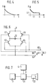
- Figure 6 shows a bridge circuit and
- Figure 7 shows another block diagram.
- FIG. 1 shows a generator 4, which is connected to a control 3 for an ultrasound sensor (US sensor), not shown.
- the generator 4 has a high-impedance source 1, which is connected to a control input of the control 3 via a capacitor 2 connected in parallel.
- the high-resistance source 1 has a voltage source with a high-resistance internal resistance, the output voltage of which can be controlled by charging and discharging the capacitor 2.
- the output of the control 3 is connected to the input of the driver stage 31.
- a control curve (envelope curve V) for the decay behavior of the US sensor 32 can be specified in accordance with the diagram in FIG. 4 (FIG. 3).
- the control 3 is known per se, for example, from the publication 'Ultrasound location system for industrial trucks', Prof. Wellhausen, Electronics 9 / 27.4.1990, pages 100 to 105.
- FIG. 2 shows a further exemplary embodiment in which the generator 4 has a low-resistance source 20 in addition to the high-resistance source 1.
- the arrangement corresponds to that of FIG. 1, the low-resistance source 20 being connected in parallel with the output of the high-resistance source 1 via a diode 21.
- the output is connected to the control 3 and its output to the driver stage 31.
- FIG. 3 shows a basic block diagram, the generator 4, the control 3, the driver stage 31 and the US sensor 32 being connected in series.
- the US sensor 32 is supplied by the control voltage with the envelope V of the driver stage 31.
- the driver stage 31 contains circuit breakers that deliver the control current or the control voltage in time with the control 3.
- a semiconductor bridge circuit can be provided, in the branches of which the transistors 61, 62, 63, 64 are arranged.
- the US sensor 32 is arranged in the bridge branch, while the generator 4 supplies the bridge with the voltage V in accordance with FIG.
- the transistors 61, 62, 63, 64 are activated in phase opposition with the voltages U S1 and U S2 .
- the mode of operation of this circuit arrangement is explained in more detail with reference to FIGS. 4 and 5.
- the basic idea of influencing the decay curve of the US sensor 32 by means of electronic switching elements is implemented in a particularly simple and advantageous manner in accordance with the block diagram in FIG. 1.
- the capacitor 2 results in the curve shown in FIG. 4 as the envelope curve for the voltage amplitude of the transmit pulses, the envelope curve falling within the time T from the maximum value V approximately towards the value zero.
- the decay time depending on the exponential function shown, depends on the capacitance of the capacitor 2 and the internal resistance of the control with driver stage 3. By varying the values, almost any desired decay curve can be achieved.
- the decay curve (envelope curve) of FIG. 5 is achieved with the circuit arrangement according to FIG.
- the envelope falls at the time t1 to the voltage value U1 in a manner similar to that in the diagram in FIG. 4.
- a voltage is fed into the capacitor C2 via the diode 21, so that the envelope in the time phase t1 until T is approximately constant.
- the amplitude within this period is significantly lower than the maximum value of the amplitude. This advantageously has the effect that, because of the reduced output power, the emitted secondary spectra do not lead to undesired noises.
- the holding level U1 is kept so low that the US sensor 32 continues to be constantly excited during the pulse duration T. After the pulse duration T has elapsed, a dead phase begins with the subsequent measuring phase.
- a preferred application of the circuit arrangement according to the invention is an ultrasound distance measurement, as is used, for example, as a parking aid for motor vehicles.
- Ultrasonic distance measurement is known per se from EP-0 152 895 B1.
- a contactless distance measurement is also known from EP 0 320 695 A1.
- the electroacoustic transducer designed as an ultrasonic sensor is already known from DE 34 41 684 A1.
Landscapes
- Engineering & Computer Science (AREA)
- Radar, Positioning & Navigation (AREA)
- Remote Sensing (AREA)
- Physics & Mathematics (AREA)
- Computer Networks & Wireless Communication (AREA)
- General Physics & Mathematics (AREA)
- Acoustics & Sound (AREA)
- Mechanical Engineering (AREA)
- Signal Processing (AREA)
- Transportation (AREA)
- Human Computer Interaction (AREA)
- Measurement Of Velocity Or Position Using Acoustic Or Ultrasonic Waves (AREA)
Description
- Die Erfindung geht aus von einer Schaltungsanordnung zur Dämpfung eines Ultraschallwandlers nach der Gattung des Hauptanspruchs. Eine derartige Schaltungsanordnung ist aus der DE-C-862 274 bekannt.
- Es ist schon bekannt, insbesondere Ultraschallwandler, die zum Betrieb sowohl als Sender als auch als Empfänger ausgebildet sind, durch Verwendung geeigneter Dämpfungsmaterialien so auszubilden, daß die Schwingmembran des Ultraschallwandlers nach möglichst kurzer Zeit ausschwingt. Eine kurze Abklingdauer nach dem Abschalten der impulsartigen Ansteuerung ist erwünscht, um kurze Meßintervalle zu erhalten. Dabei entstehen jedoch Nebenspektren, die unerwünschte Geräusche erzeugen. Es hat sich auch gezeigt, daß die verwendeten Dämpfungsmaterialien nur für eine bestimmte vorgegebene Frequenz wirksam sind und bei geänderter Ansteuerfrequenz nicht mehr die gewünschte Wirkung zeigen. Des weiteren ist bei der Herstellung der Dämpfungsmaterialien und der Dämpfungskörper mit großen Fertigungstoleranzen zu rechnen, die die Abkling-Charakteristik des Ultraschallwandlers ungünstig beeinflussen.
- Die erfindungsgemäße Schaltungsanordnung mit den kennzeichnenden Merkmalen des Hauptanspruchs hat demgegenüber den Vorteil, daß die Abkling-Charakteristik und die Abklingdauer des Sendesignales durch die Ansteuerkurve derart vorgebbar ist, daß die Erzeugung der Nebenspektren und der Geräuschentwicklung wesentlich vermindert wird. Auftretende Fertigungstoleranzen werden dadurch vorteilhaft beeinflußt, so daß eine schnelle Meßfolge auch für kurze Abstände möglich ist.
- Durch die in den abhängigen Ansprüchen aufgeführten Maßnahmen sind vorteilhafte Weiterbildungen und Verbesserung der im Hauptanspruch angegebenen Schaltungsanordnung möglich. Besonders vorteilhaft ist, daß der Generator für die Beeinflussung der Ansteuerspannung ein Mittel aufweist, das innerhalb einer vorgegebenen Zeitdauer die Spannung auf Null absenkt. Dieses wird in vorteilhafter Weise dadurch erreicht, daß die Amplitude der Sendeimpulse durch eine verringerte Anregung des Ultraschallwandlers vermindert wird.
- Eine besonders einfache Beeinflussung erfolgt durch ein RC-Glied, das eine Tiefpaßcharakteristik aufweist.
- Durch die vorgeschlagenen Schaltungsmaßnahmen werden ebenfalls die Amplituden der Frequenz-Nebenspektren beim Abschaltvorgang vorteilhaft verringert. Durch die geringere Anregung gegen Ende des Implses werden kürzere Schaltintervalle bzw. Betriebsintervalle des Ultraschallwandlers ermöglicht. Bei der Beeinflussung der Abstrahlkeule der Sendeimpulse geht man von der mathematischen Annahme aus, daß ein Dirac-Stoß eine ideale Halbkugelwelle bei einem Ultraschall-Sensor erzeugen würde. Nutzt man nur wenige Anregungsschwingungen, welche zusätzlich noch amplitudenmoduliert werden, wird die akustische Keule verbreitert (Dirac-Stoß-Effekt).
- Weiterhin ist vorteilhaft, daß durch eine Amplitudenmodulierung der Ausgangsspannung die Nebenspektren vermindert werden und damit eine Verringerung der Abschaltgeräusche stattfindet. Dieses wird dadurch erreicht, daß die Abklingdauer zunächst auf einen Sprungwert abfällt, der für eine bestimmte Zeitdauer konstant ist. Erst nach Ablauf dieser Zeitdauer wird die Ausgangsspannung abgeschaltet. Dabei ist die Realisierung mit einfachen und preiswerten Bauelementen wie Widerstände und Dioden besonders vorteilhaft.
- Weiterhin ergibt sich eine einfache Ansteuermöglichkeit für den Sensor durch die Halbleiterbrückenschaltung, wodurch der Spannungshub für den Ultraschallsensor im Brückenzweig annähernd verdoppelt wird. Eine vorteilhafte Anwendung erfolgt im Kraftfahrzeug zur Abstandsbestimmung beim Einparken.
- In der Zeichnung sind in den Figuren 1 und 2 zwei Ausführungsbeispiele der Erfindung dargestellt. Figur 3 zeigt ein Blockschaltbild der Anordnung und die Figuren 4 und 5 zeigen Diagramme mit Abklingkurven, Figur 6 zeigt eine Brückenschaltung und Figur 7 zeigt ein weiteres Blockschaltbild.
- Figur 1 zeigt einen Generator 4, der mit einer Ansteuerung 3 für einen nicht dargestellten Ultraschallsensor (US-Sensor) verbunden ist. Der Generator 4 weist eine hochohmige Quelle 1 auf, die über einen parallelgeschalteten Kondensator 2 mit einem Steuereingang der Ansteuerung 3 verbunden ist. Die hochohmige Quelle 1 weist eine Spannungsquelle mit einem hochohmigen Innenwiderstand auf, deren Ausgangsspannung durch Aufladen und Entladen des Kondensators 2 steuerbar ist. Der Ausgang der Ansteuerung 3 ist mit dem Eingang der Treiberstufe 31 verbunden. Auf diese Weise kann entsprechend dem Diagramm der Figur 4 eine Steuerkurve (Hüllkurve V) für das Abklingverhalten des US-Sensors 32 vorgegeben werden (Figur 3). Die Ansteuerung 3 ist per se beispielsweise aus der Veröffentlichtung 'Ultraschall-Ortungssystem für Flurförderfahrzeuge', Prof. Wellhausen, Elektronik 9/27.4.1990, Seite 100 bis 105 bekannt.
- Figur 2 zeigt ein weiteres Ausführungsbeispiel, bei dem der Generator 4 neben der hochohmigen Quelle 1 eine niederohmige Quelle 20 aufweist. Die Anordnung entspricht derjenigen der Figur 1, wobei die niederohmige Quelle 20 über eine Diode 21 dem Ausgang der hochohmigen Quelle 1 parallelgeschaltet ist. Der Ausgang ist mit der Ansteuerung 3 verbunden und deren Ausgang mit der Treiberstufe 31.
- Figur 3 zeigt ein prinzipielles Blockschaltbild, wobei der Generator 4, die Ansteuerung 3, die Treiberstufe 31 und der US-Sensor 32 in Reihe geschaltet sind. Dabei wird der US-Sensor 32 von der Steuerspannung mit der Hüllkurve V der Treiberstufe 31 versorgt. Die Treiberstufe 31 enthält Leistungsschalter, die den Steuerstrom bzw. die Steuerspannung im Takt der Ansteuerung 3 liefern.
- Alternativ kann zur Erhöhung der Ansteuerspannung des US-Sensors 32 gemäß Figur 6 eine Halbleiterbrückenschaltung vorgesehen werden, in deren Zweige die Transistoren 61, 62, 63, 64 angeordnet sind. Im Brückenzweig ist der US-Sensor 32 angeordnet, während die Versorgung der Brücke entsprechend Figur 7 vom Generator 4 mit der Spannung V erfolgt. Die Transistoren 61, 62, 63, 64 werden im Betriebsfall gegenphasig mit den Spannungen US1 und US2 angesteuert.
- Die Funktionsweise dieser Schaltungsanordnung wird anhand der Figuren 4 und 5 näher erläutert. Die prinzipielle Idee, die Abklingkurve des US-Sensors 32 mittels elektronischer Schaltelemente zu beeinflussen, wird in besonders einfacher und vorteilhafter Weise entsprechend dem Blockschaltbild der Figur 1 realisiert. Durch den Kondensator 2 ergibt sich als Hüllkurve für die Spannungsamplitude der Sendeimpulse die nach Figur 4 dargestellte Kurve, wobei die Hüllkurve innerhalb der Zeit T vom Maximalwert V etwa gegen den Wert Null abfällt. Dabei ist die Abklingdauer entsprechend der dargestellten Exponentialfunktion abhängig von der Kapazität des Kondensators 2 und dem Innenwiderstand der Ansteuerung mit Treiberstufe 3. Durch Variation der Werte kann nahezu jede gewünschte Abklingkurve erreicht werden.
- Mit der Schaltungsanordnung gemäß der Figur 2 wird die Abklingkurve (Hüllkurve) der Figur 5 erreicht. Im ersten Teil der Abklingdauer fällt die Hüllkurve zum Zeitpunkt t1 auf den Spannungswert U1 ähnlich ab wie im Diagramm der Figur 4. Durch die niederohmige Quelle 20 wird über die Diode 21 eine Spannung in den Kondensator C2 eingespeist, so daß die Hüllkurve in der Zeitphase t1 bis T etwa konstant ist. Die Amplitude innerhalb dieser Zeitspanne ist dabei wesentlich niedriger als der Maximalwert der Amplitude. Dadurch wird vorteilhaft bewirkt, daß wegen der verringerten Ausgangsleistung die abgestrahlten Nebenspektren nicht zu unerwünschten Geräuschen führen. Der Haltepegel U1 wird so niedrig gehalten, daß der US-Sensor 32 während der Impulsdauer T weiterhin konstant angeregt wird. Nach Ablauf der Impulsdauer T beginnt eine Totphase mit anschließender Meßphase.
- Eine bevorzugte Anwendung der erfindungsgemäßen Schaltungsanordnung ist eine Ultraschall-Entfernungsmessung, wie sie beispielsweise als Einparkhilfe für Kraftfahrzeuge verwendet wird. Die Ultraschall-Entfernungsmessung ist per se aus der EP-0 152 895 B1 bekannt. Aber auch aus der EP 0 320 695 A1 ist eine berührungslose Abstandsmessung bekannt. Der als Ultraschall-Sensor ausgebildete elektroakustische Wandler ist schon aus der DE 34 41 684 A1 bekannt.
Claims (7)
- Schaltungsanordnung zur Dämpfung eines Ultraschallwandlers, der zum Betrieb sowohl als Sender als auch als Empfänger ausgebildet ist, wobei die Schaltungsanordnung einen Generator (4) aufweist und wobei der Generator (4) ausgebildet ist, die Ansteuerspannung (V) für den Ultraschallwandler (32) derart zu steuern, daß die der Ansteuerspannung entsprechende Amplitude des abgestrahlten Ultraschallwandlersignals nach einer vorgegebenen Hüllkurve für die Abklingdauer (V) abklingt, dadurch gekennzeichnet, daß der Generator (4) ein weiteres Mittel (20, 21) aufweist, durch das die vorgegebene Hüllkurve (V) innerhalb einer Zeitdauer t1 zunächst auf einen von Null verschiedenen Spannungswert U1 abfallt und daß anschließend der Spannungswert U1 der Hüllkurve (V) für eine bestimmte Zeitdauer T-t1 nahezu konstant ist.
- Schaltungsanordnung nach Anspruch 1, dadurch gekennzeichnet, daß der Generator (4) ein Mittel (2) aufweist, durch das die vorgegebene Hüllkurve (V) der Ansteuerspannung nach der Zeitdauer T etwa gegen den Wert Null abfällt.
- Schaltungsanordnung nach Anspruch 2, dadurch gekennzeichnet, daß das Mittel (2) ein als Tiefpaß geschaltetes RC-Glied (1, 2) aufweist.
- Schaltungsanordnung nach Anspruch 1, dadurch gekennzeichnet, daß das weitere Mittel (20, 21) eine der Ansteuerung (3) vorgeschaltete niederohmige Quelle (20) mit einer in Reihe geschalteten Diode (21) aufweist.
- Schaltungsanordnung nach einem der vorhergehenden Ansprüche, dadurch gekennzeichnet, daß der Ultraschall-Sensor 32 im Querzweig einer Transistorbrückenschaltung (61, 62, 63, 64) angeordnet ist, daß die Transistoren (61, 62, 63, 64) im Betriebsfall über ihre Eingänge (US1, US2) gegenphasig ansteuerbar sind und daß zur Versorgung die Brücke mit dem Generator (4) verbunden ist.
- Schaltungsanordnung nach einem der vorhergehenden Ansprüche, dadurch gekennzeichnet, daß die Schaltungsanordnung zur Anstandsmessung an einem Kraftfahrzeug verwendbar ist.
- Schaltungsanordnung nach Anspruch 6, dadurch gekennzeichnet, daß die Schaltungsanordnung für eine Einparkhilfe verwendbar ist.
Applications Claiming Priority (2)
| Application Number | Priority Date | Filing Date | Title |
|---|---|---|---|
| DE4314247A DE4314247A1 (de) | 1993-04-30 | 1993-04-30 | Schaltungsanordnung zur Dämpfung eines Ultraschallwandlers |
| DE4314247 | 1993-04-30 |
Publications (2)
| Publication Number | Publication Date |
|---|---|
| EP0623395A1 EP0623395A1 (de) | 1994-11-09 |
| EP0623395B1 true EP0623395B1 (de) | 1997-01-15 |
Family
ID=6486814
Family Applications (1)
| Application Number | Title | Priority Date | Filing Date |
|---|---|---|---|
| EP94104661A Expired - Lifetime EP0623395B1 (de) | 1993-04-30 | 1994-03-24 | Schaltungsanordnung zur Dämpfung eines Ultraschallwandlers |
Country Status (4)
| Country | Link |
|---|---|
| EP (1) | EP0623395B1 (de) |
| JP (1) | JP3654596B2 (de) |
| KR (1) | KR100334193B1 (de) |
| DE (2) | DE4314247A1 (de) |
Cited By (2)
| Publication number | Priority date | Publication date | Assignee | Title |
|---|---|---|---|---|
| EP3208634A1 (de) | 2016-02-17 | 2017-08-23 | ELMOS Semiconductor Aktiengesellschaft | Ultraschallmesssystem, insbesondere zur abstandsmessung und/oder als parkhilfe bei fahrzeugen |
| DE102016103514A1 (de) | 2016-02-29 | 2017-08-31 | Valeo Schalter Und Sensoren Gmbh | Filtereinrichtung zum Filtern einer Versorgungsspannung eines Ultraschallsensors eines Kraftfahrzeugs, Ultraschallsensorvorrichtung sowie Kraftfahrzeug |
Families Citing this family (8)
| Publication number | Priority date | Publication date | Assignee | Title |
|---|---|---|---|---|
| DE10314922A1 (de) * | 2003-04-01 | 2004-10-14 | Endress + Hauser Gmbh + Co. Kg | Mit Ultraschall arbeitendes Füllstandsmeßgerät |
| DE102006054605A1 (de) * | 2006-11-20 | 2008-05-21 | Robert Bosch Gmbh | Abstandsmessverfahren und Abstandsmessvorrichtung |
| DE102010062930A1 (de) | 2010-12-13 | 2012-06-14 | Robert Bosch Gmbh | Verfahren zur Erfassung eines Objekts in einem Umfeld und Vorrichtung zur Erzeugung eines Ultraschallsignals |
| DE102011083337A1 (de) * | 2011-09-23 | 2013-03-28 | Robert Bosch Gmbh | Verfahren zur Erfassung der Fahrzeugumgebung eines Fahrzeuges mittels Ultraschall und Vorrichtung zum Durchführen des Verfahrens |
| DE102011089542A1 (de) | 2011-12-22 | 2013-06-27 | Robert Bosch Gmbh | Verfahren und Schaltungsanordnung zur Ansteuerung eines Ultraschallsensors |
| DE102012201100A1 (de) | 2012-01-26 | 2013-08-01 | Robert Bosch Gmbh | Ansteuerungsschaltung und Verfahren zur aktiven Dämpfung eines Ultraschallwandlers, sowie Ultraschall-Messsystem |
| DE102012201920A1 (de) | 2012-02-09 | 2013-08-14 | Robert Bosch Gmbh | Verfahren und Messsystem zum Detektieren von Objekten mittels Ultraschall |
| US10361559B2 (en) | 2017-10-27 | 2019-07-23 | Valeo Schalter Und Sensoren Gmbh | Dynamic filtering device for sensor |
Citations (1)
| Publication number | Priority date | Publication date | Assignee | Title |
|---|---|---|---|---|
| EP0152895A2 (de) * | 1984-02-18 | 1985-08-28 | Bayerische Motoren Werke Aktiengesellschaft, Patentabteilung AJ-3 | Schaltanordnung für einen Ultraschall-Entfernungsmesser |
Family Cites Families (1)
| Publication number | Priority date | Publication date | Assignee | Title |
|---|---|---|---|---|
| DE862274C (de) * | 1942-02-08 | 1953-01-08 | Atlas Werke Ag | Vorrichtung zum Impulsbetrieb von Elektromagneten, insbesondere von Magnetostriktionsschwingern zur Erzeugung von Schallimpulsen |
-
1993
- 1993-04-30 DE DE4314247A patent/DE4314247A1/de not_active Withdrawn
-
1994
- 1994-03-24 EP EP94104661A patent/EP0623395B1/de not_active Expired - Lifetime
- 1994-03-24 DE DE59401571T patent/DE59401571D1/de not_active Expired - Fee Related
- 1994-04-27 JP JP09006494A patent/JP3654596B2/ja not_active Expired - Fee Related
- 1994-04-28 KR KR1019940009581A patent/KR100334193B1/ko not_active IP Right Cessation
Patent Citations (1)
| Publication number | Priority date | Publication date | Assignee | Title |
|---|---|---|---|---|
| EP0152895A2 (de) * | 1984-02-18 | 1985-08-28 | Bayerische Motoren Werke Aktiengesellschaft, Patentabteilung AJ-3 | Schaltanordnung für einen Ultraschall-Entfernungsmesser |
Cited By (3)
| Publication number | Priority date | Publication date | Assignee | Title |
|---|---|---|---|---|
| EP3208634A1 (de) | 2016-02-17 | 2017-08-23 | ELMOS Semiconductor Aktiengesellschaft | Ultraschallmesssystem, insbesondere zur abstandsmessung und/oder als parkhilfe bei fahrzeugen |
| DE102016103514A1 (de) | 2016-02-29 | 2017-08-31 | Valeo Schalter Und Sensoren Gmbh | Filtereinrichtung zum Filtern einer Versorgungsspannung eines Ultraschallsensors eines Kraftfahrzeugs, Ultraschallsensorvorrichtung sowie Kraftfahrzeug |
| WO2017148633A1 (de) | 2016-02-29 | 2017-09-08 | Valeo Schalter Und Sensoren Gmbh | Filtereinrichtung zum filtern einer versorgungsspannung eines ultraschallsensors eines kraftfahrzeugs, ultraschallsensorvorrichtung sowie kraftfahrzeug |
Also Published As
| Publication number | Publication date |
|---|---|
| EP0623395A1 (de) | 1994-11-09 |
| JPH06347537A (ja) | 1994-12-22 |
| KR100334193B1 (ko) | 2002-09-05 |
| DE59401571D1 (de) | 1997-02-27 |
| JP3654596B2 (ja) | 2005-06-02 |
| DE4314247A1 (de) | 1994-11-03 |
| KR940025384A (ko) | 1994-11-19 |
Similar Documents
| Publication | Publication Date | Title |
|---|---|---|
| EP0033508B1 (de) | Schaltung für wechselweises Aussenden und Empfangen mit nur einem Schallgeber-Wandler | |
| EP0623395B1 (de) | Schaltungsanordnung zur Dämpfung eines Ultraschallwandlers | |
| EP2780125B1 (de) | Ultraschallwandler und korrespondierende vorrichtung zur umfelderfassung in einem fahrzeug | |
| WO2009074369A1 (de) | Sensorfunktion zur ansteuerung mit variabler sendefrequenz zum zwecke der verschmutzungserkennung | |
| WO2006061305A2 (de) | Vorrichtung und verfahren zur dämpfung eines parallelschwingkreises | |
| WO2014166835A1 (de) | Verfahren zur messung mittels ultraschall, insbesondere als parkhilfe für fahrzeuge, und ultraschallmesssysteme | |
| DE3347442A1 (de) | Einrichtung zur abstandsmessung, insbesondere fuer kraftfahrzeuge | |
| DE3513270A1 (de) | Einrichtung zur abstandsmessung, insbesondere fuer kraftfahrzeuge | |
| DE19720519A1 (de) | Vorrichtung zur Feststellung und/oder Überwachung eines Füllstandes eines Mediums in einem Behälter | |
| EP1977190B1 (de) | Entfernungsmessgerät | |
| DE4414746C2 (de) | Sende-Empfangsschaltung für ein akustisches Pulsecho-Entfernungsmeßsystem | |
| EP2692451B1 (de) | Elektrische Schaltung für den Betrieb einer Sendeempfangseinheit | |
| DE10328113B4 (de) | Vorrichtung zum Betreiben einer schwingfähigen Einheit eines Vibrationsresonators | |
| EP3423864A1 (de) | Filtereinrichtung zum filtern einer versorgungsspannung eines ultraschallsensors eines kraftfahrzeugs, ultraschallsensorvorrichtung sowie kraftfahrzeug | |
| DE19721835C2 (de) | Schaltungsanordnung zum Betreiben eines Abstandssensors, insbesondere eines Ultraschallsensors | |
| DE102020132634A1 (de) | Ultraschallsensorsystem für ein kraftfahrzeug und verfahren zum betreiben des ultraschallsensorsystems | |
| DE102012213712A1 (de) | Verfahren zum Betrieb eines Ultraschallwandlers | |
| DE3602857A1 (de) | Einrichtung zur abstandsmessung, insbesondere fuer kraftfahrzeuge | |
| DE102010062930A1 (de) | Verfahren zur Erfassung eines Objekts in einem Umfeld und Vorrichtung zur Erzeugung eines Ultraschallsignals | |
| DE4200194C2 (de) | Schwingförderanordnung | |
| DE102007062460A1 (de) | Ultraschallsensor | |
| EP2904424B1 (de) | Unterdrückung des nachschwingens eines wandlers für die umfelddetektion | |
| DE19636574C1 (de) | Wegfahrsperre für ein Kraftfahrzeug | |
| EP0327656B1 (de) | Ultraschall-Näherungsschalter | |
| DE1257903B (de) | Radar-Bake mit Halbleiterbauelementen |
Legal Events
| Date | Code | Title | Description |
|---|---|---|---|
| PUAI | Public reference made under article 153(3) epc to a published international application that has entered the european phase |
Free format text: ORIGINAL CODE: 0009012 |
|
| AK | Designated contracting states |
Kind code of ref document: A1 Designated state(s): DE FR GB IT |
|
| 17P | Request for examination filed |
Effective date: 19950509 |
|
| 17Q | First examination report despatched |
Effective date: 19960112 |
|
| GRAG | Despatch of communication of intention to grant |
Free format text: ORIGINAL CODE: EPIDOS AGRA |
|
| GRAH | Despatch of communication of intention to grant a patent |
Free format text: ORIGINAL CODE: EPIDOS IGRA |
|
| GRAH | Despatch of communication of intention to grant a patent |
Free format text: ORIGINAL CODE: EPIDOS IGRA |
|
| GRAA | (expected) grant |
Free format text: ORIGINAL CODE: 0009210 |
|
| AK | Designated contracting states |
Kind code of ref document: B1 Designated state(s): DE FR GB IT |
|
| ET | Fr: translation filed | ||
| REF | Corresponds to: |
Ref document number: 59401571 Country of ref document: DE Date of ref document: 19970227 |
|
| ITF | It: translation for a ep patent filed |
Owner name: 0414;07MIFSTUDIO JAUMANN |
|
| GBT | Gb: translation of ep patent filed (gb section 77(6)(a)/1977) |
Effective date: 19970320 |
|
| PLBE | No opposition filed within time limit |
Free format text: ORIGINAL CODE: 0009261 |
|
| STAA | Information on the status of an ep patent application or granted ep patent |
Free format text: STATUS: NO OPPOSITION FILED WITHIN TIME LIMIT |
|
| 26N | No opposition filed | ||
| REG | Reference to a national code |
Ref country code: GB Ref legal event code: IF02 |
|
| PGFP | Annual fee paid to national office [announced via postgrant information from national office to epo] |
Ref country code: IT Payment date: 20060331 Year of fee payment: 13 |
|
| PGFP | Annual fee paid to national office [announced via postgrant information from national office to epo] |
Ref country code: DE Payment date: 20060516 Year of fee payment: 13 |
|
| PGFP | Annual fee paid to national office [announced via postgrant information from national office to epo] |
Ref country code: GB Payment date: 20070323 Year of fee payment: 14 |
|
| PG25 | Lapsed in a contracting state [announced via postgrant information from national office to epo] |
Ref country code: DE Free format text: LAPSE BECAUSE OF NON-PAYMENT OF DUE FEES Effective date: 20071002 |
|
| PGFP | Annual fee paid to national office [announced via postgrant information from national office to epo] |
Ref country code: FR Payment date: 20070321 Year of fee payment: 14 |
|
| GBPC | Gb: european patent ceased through non-payment of renewal fee |
Effective date: 20080324 |
|
| REG | Reference to a national code |
Ref country code: FR Ref legal event code: ST Effective date: 20081125 |
|
| PG25 | Lapsed in a contracting state [announced via postgrant information from national office to epo] |
Ref country code: FR Free format text: LAPSE BECAUSE OF NON-PAYMENT OF DUE FEES Effective date: 20080331 |
|
| PG25 | Lapsed in a contracting state [announced via postgrant information from national office to epo] |
Ref country code: GB Free format text: LAPSE BECAUSE OF NON-PAYMENT OF DUE FEES Effective date: 20080324 |
|
| PG25 | Lapsed in a contracting state [announced via postgrant information from national office to epo] |
Ref country code: IT Free format text: LAPSE BECAUSE OF NON-PAYMENT OF DUE FEES Effective date: 20070324 |