EP0623318B1 - Sicherheitshaltebolzen für Kopfklemme - Google Patents
Sicherheitshaltebolzen für Kopfklemme Download PDFInfo
- Publication number
- EP0623318B1 EP0623318B1 EP94302435A EP94302435A EP0623318B1 EP 0623318 B1 EP0623318 B1 EP 0623318B1 EP 94302435 A EP94302435 A EP 94302435A EP 94302435 A EP94302435 A EP 94302435A EP 0623318 B1 EP0623318 B1 EP 0623318B1
- Authority
- EP
- European Patent Office
- Prior art keywords
- head
- bracket
- ring gear
- operating handle
- pin
- Prior art date
- Legal status (The legal status is an assumption and is not a legal conclusion. Google has not performed a legal analysis and makes no representation as to the accuracy of the status listed.)
- Expired - Lifetime
Links
- 230000007246 mechanism Effects 0.000 claims description 15
- 239000012530 fluid Substances 0.000 claims description 3
- 210000003625 skull Anatomy 0.000 description 10
- 208000027418 Wounds and injury Diseases 0.000 description 2
- 230000006378 damage Effects 0.000 description 2
- 208000014674 injury Diseases 0.000 description 2
- 238000000034 method Methods 0.000 description 2
- 230000001954 sterilising effect Effects 0.000 description 2
- 238000004659 sterilization and disinfection Methods 0.000 description 2
- 238000001356 surgical procedure Methods 0.000 description 2
- 241001354471 Pseudobahia Species 0.000 description 1
- 230000001419 dependent effect Effects 0.000 description 1
- 229910052500 inorganic mineral Inorganic materials 0.000 description 1
- 239000000463 material Substances 0.000 description 1
- 239000011707 mineral Substances 0.000 description 1
- 239000002245 particle Substances 0.000 description 1
- 229920001343 polytetrafluoroethylene Polymers 0.000 description 1
Images



Classifications
-
- A—HUMAN NECESSITIES
- A61—MEDICAL OR VETERINARY SCIENCE; HYGIENE
- A61B—DIAGNOSIS; SURGERY; IDENTIFICATION
- A61B90/00—Instruments, implements or accessories specially adapted for surgery or diagnosis and not covered by any of the groups A61B1/00 - A61B50/00, e.g. for luxation treatment or for protecting wound edges
- A61B90/10—Instruments, implements or accessories specially adapted for surgery or diagnosis and not covered by any of the groups A61B1/00 - A61B50/00, e.g. for luxation treatment or for protecting wound edges for stereotaxic surgery, e.g. frame-based stereotaxis
- A61B90/14—Fixators for body parts, e.g. skull clamps; Constructional details of fixators, e.g. pins
Definitions
- the present invention relates to a skull clamp or surgical head clamp to hold the head of the patient in position for neurosurgical operations and for other procedures involving the patient's head.
- Surgical head clamps or skull clamps generally are provided with two types of mechanisms to hold the head in position.
- One type of clamp uses pads that are forced against the patient's head to hold the head in position. Examples of head clamps of this type are disclosed in U.S. Patents 4,108,426 and 4,545,572.
- a second type of head clamp uses a series of head engaging pins which engage the patient's skull at three points and provide positive anchorage of the head engaging pins into the skull. If the head engaging pins are held in a stable position, there is little likelihood that the skull will move relative to the head engaging pins during the surgical procedure.
- the head clamp disclosed in U.S. Patent 2,966,383 shows a three pin arrangement with the head engaging pins carried on hinged arms.
- U.S. Patent 3,099,441 discloses a surgical head clamp which contains two head engaging pins on a bracket supported by an arm and a third head engaging pin supported by another arm in the device. The two arms are brought together to adjust the space between the head engaging pins to fit the dimensions of the patient's head.
- U.S. Patent 3,835,861 discloses a surgical head clamp having three head engaging pins with two of the pins on a bracket and a third pin on a moveable pin carrier in which the moveable pin is held on a threaded pin carrier so finer adjustments in the relationship of the head engaging pins to the patient can be made.
- U.S. Patent 4,169,478 also discloses a surgical head clamp with three head engaging pins which is similar to that shown in U.S. Patent 3,835,861.
- the head clamp includes a mechanism to rotate the bracket containing the two pins and reposition the head of the patient without releasing the head engaging pins from the patient's skull.
- the mechanism disclosed in U.S. Patent 4,169,478 to prevent rotation employs interlocking teeth on stop members which are forced into engagement by ball actuators. The ball actuators move from dished sockets in the unlocked position to the lands between the dished sockets in the locket position. Upon repeated use and upon repeated sterilization, there is a tendency for foreign particles and debris to accumulate in the dished sockets or on the lands which prevent the positive locking of the bracket.
- the U.S. Patent 5,254,079 discloses a head clamp which employs index pins between a rotatable bracket and the frame of the head clamp to prevent inadvertent rotation of the bracket.
- the bracket cannot be adjusted when the head engaging pins are engaging the patient's head. The patient's head must be disengaged from the pins before the bracket can be rotated.
- the head clamp of the present invention provides the flexibility of the device described in U.S. Patent 4,169,478 mentioned above but prevents the inadvertent rotation of the bracket.
- the present head clamp includes two head engaging pins secured to a rocker arm on a bracket and a third head engaging pin which is held in a movable pin carrier.
- the present head clamp can be adjusted to reposition the patient's head without disengaging the head engaging pins from the patient but the present head clamp does have a positive locking mechanism to prevent inadvertent rotation of the bracket.
- the locking mechanism also may be visually inspected to insure that bracket is positively locked so it will not rotate.
- the present head clamp employs ball actuators as disclosed in U.S. Patent 4,169,478 to allow the bracket to be rotated without releasing the head engaging pins from the patient's head.
- the head clamp of the present invention also provides a safety lock mechanism including a safety locking mechanism that can be unlocked to provide for the rotation of an operating handle, and the rotation of a rocker arm to allow the patient's head to be repositioned without disengaging the head engaging pins from the patient's head. When the patient's head has been repositioned, the safety locking mechanism can be locked to prevent inadvertent rotation.
- the head clamp of the present invention provides the adjustment capability of the head clamp disclosed in U.S. Patent 4,169,478 and also provides the ability to prevent the rotatable bracket of the head clamp from inadvertently rotating. This is accomplished by employing a safety locking pin as a secondary lock to positively lock the rotatable bracket of the head clamp in position when the operating handle is in the locked position.
- Fig. 1 is a plan view of the surgical head clamp in the present invention showing the relative position of the head in dash lines.
- Fig. 2 is an exploded view of a portion of the head clamp shown in Fig. 1, showing the details of the rotating and locking mechanism of the present invention.
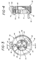
- Fig. 3 is an end view of the operating handle.
- Fig. 4 is a detailed view partially in section of the locking handle and safety locking pin of the present invention as taken along line 4-4 of Fig. 3.
- Fig. 5 is a cross sectional view of the operating handle in the locked position.
- the basic skull clamp of the present invention as shown in Fig. 1 is similar to the clamp which is shown in U.S. Patents 3,835,861 and 4,169,478.
- the clamp 10 includes a main fixed section 11 and a ratchet section 12. These sections are connected in a telescoping relationship with the ratchet section 12 being capable of telescoping into the fixed section 11.
- the ratchet section 12 has a number of teeth 17 which can engage teeth (not shown) on a plunger lock 39 to lock the ratchet section the fixed section of the clamp.
- On fixed section 11 there is an arm 13 which terminates in a boss 21 which has a hexagonal interior configuration.
- An arm 14 on ratchet section 12 terminates in an internally threaded boss 18 to receive a pin carrier 19.
- the pin carrier 19 has a knob 33 at one end and a pin receiving bore at the other end.
- a head engaging pin 20 is seated in the bore.
- the head clamp is secured to the operating room table through a sunburst clamp 15 which has teeth 16 to engage matching teeth on a support, (not shown), which would be affixed to the operating room table.
- the fixed arm section 13 terminates in a boss 21.
- This boss has a hexagonal opening, not shown, into which the operating handle and locking mechanism, shown in an exploded view in Fig. 2, is mounted.
- a rotatable bracket 24, mounting a rocker arm 23, is affixed to the locking mechanism generally shown as 22. There are bores at each end of the rocker arm to receive the head engaging pins 40.
- the bracket 24 is capable of rotation to adjust the position of the patient's head without removing the head engaging pins 20 and 40 from the patient's head.
- the locking mechanism is similar to that shown in U.S. Patent 4,169,478 and is depicted in an exploded view in Fig. 2.
- Fig. 2 the rocker arm 23 and the rotatable bracket 24 have been turned 90° from the position shown in Fig. 1.
- the rocker arm 23 is held to the rotatable bracket 24 by a single bolt 35 secured with a nut 36. As the rocker arm is held with a single bolt 35, it is capable of pivoting to adjust to the configuration of the patient's skull.
- the end of the rotatable bracket 24 opposed to the end to which the rocker arm 23 is affixed contains a ring gear 25 which has teeth 26 which engage teeth 27 on a moveable ring gear 28.
- the moveable ring gear 28 is provided with three dished sockets 29 on the face opposite the teeth 27. Dished sockets 29 on the ring gear 28 are sized to receive one of three ball actuators 30.
- the ball actuators 30 rest in the dished sockets 29 of the movable ring gear 28 and the dished sockets 43 of the actuator disk 31 when the operating handle 32 is in the unlocked position.
- the rotatable bracket is affixed to the boss 21 by a bolt 41 which extends through a washer 45 and through the operating handle 32 and the moveable ring gear 28, and into threaded openings in the ring gear 25 and the rotatable bracket 24.
- the head of the bolt 41 can be covered with a cap 42 to provide an improved appearance to the device.
- the operating handle 32 has a pin receiving slot 48 to receive a pin 49 which is secured to the boss 21.
- the pin 49 can move in the pin receiving slot 48, which extends around an arc of approximately 60° on the face of the operating handle 32, when the handle is rotated.
- the bracket 24 can be rotated.
- the bracket is locked .
- the locking pin 50 has a length dimension which is at least equal to the thickness of the operating handle 32.
- the locking pin is attached to a locking slide 52 and is biased into a locked position by the spring 54.
- a corresponding opening 47 on the boss 32 to receive the locking pin 50.
- a dovetail slot 60 in the operating handle 32 there is a dovetail slot 60 in the operating handle 32.
- a corresponding dovetail 62 on the locking slide 52 to provide slidable mounting of the locking slide 52 to the operating handle 32.
- the use of the safety locking pin prevents the inadvertent movement of the operating handle 32 which could cause the rotating of the bracket 24 and possible injury to a patient.
- the safety locking pin can only be seated in the opening 47 in the boss 21 when the operating handle 32 is in the locked position.
- the locking slide 52 extends outwardly beyond the outer face of the operating handle when the locking slide 52 is not in the locked position. The operating room staff can note the position of the slide to determine if the operating handle is in the locked position.
- channels 55 at the base of the dished sockets 43.
- the channels extend through the actuator disk 32.
- the channels provide an opening or passageway for fluid to be drained and removed from the dished sockets during the vacuum cycle of a sterilization process used to sterilize the head clamp prior to use. This prevents the build up of mineral scale in the dished sockets which could interfere with the operation of the ball actuators to place the bracket 25 in a locked position.
- the patient's head would be affixed to the head clamp by positioning the head between the fixed arm 13 and the ratchet section of the arm 14.
- the ratchet section would then be telescoped into the fixed section so that the locking pins would engage the patient's skull.
- the pin carrying knob 33 could then be rotated to ensure the proper contact of the pin 20 with the patient's skull.
- the locking slide 52 would be moved outwardly which would carry the locking pin out of the opening 47 in the fixed arm boss 21.
- the operating handle could then be rotated from the locking position to the unlocking position which would move the ball actuators into the recesses formed by the alignment of the dished sockets 29 is the movable ring gear and the dished sockets 43 in the actuator disk 31. This would release the spring 34 and would then exert a force on the moveable ring gear 28 to separate the teeth 26 from the teeth 27.
- the bracket 24 would then be free to rotate to reposition the patient's head.
- the operating handle When the patient's head is in the proper position the operating handle would be turned until it had moved to a locked position. This movement will move the ball actuators out of the recesses formed by the dished sockets 29 and 43 unto the lands 44 and force the teeth 27 on movable ring gear 28 into engagement with the teeth 26 on the ring gear 25.
- the safety locking pin 50 could then engage the opening 47 in the boss 21. This locking pin ensures that the operating handle is in the locked position and prevents the inadvertent rotation of the operating handle 32 and the bracket 24. If the locking pin 50 is not fully seated in the opening 47, the slide 52 will extend beyond the outer face of the operating handle 32.
Landscapes
- Health & Medical Sciences (AREA)
- Surgery (AREA)
- Life Sciences & Earth Sciences (AREA)
- Biomedical Technology (AREA)
- Medical Informatics (AREA)
- Oral & Maxillofacial Surgery (AREA)
- Nuclear Medicine, Radiotherapy & Molecular Imaging (AREA)
- Engineering & Computer Science (AREA)
- Neurosurgery (AREA)
- Heart & Thoracic Surgery (AREA)
- Pathology (AREA)
- Molecular Biology (AREA)
- Animal Behavior & Ethology (AREA)
- General Health & Medical Sciences (AREA)
- Public Health (AREA)
- Veterinary Medicine (AREA)
- Accommodation For Nursing Or Treatment Tables (AREA)
- Apparatus For Radiation Diagnosis (AREA)
- Surgical Instruments (AREA)
Claims (4)
- Chirurgische Kopfklemme (10), umfassend:einen Rahmen;einen ersten Kopfhaltestift (20), der an dem Rahmen gehalten wird;einen Halter (24), der drehbar an dem Rahmen gehalten wird, wobei die Drehachse mit dem ersten Kopfhaltestift (20) ausgerichtet ist und der Halter (24) mit Abstand von dem ersten Kopfhaltestift (20) angeordnet ist;zweite und dritte Kopfhaltestifte (40), die an dem Halter (24) befestigt sind;eine Vorrichtung (15, 16) für einen Vorschub des ersten Kopfhaltestiftes (20) axial in Richtung auf den Halter (24), so daß die Kopfhaltestifte (20, 40) mit dem Kopf eines Patienten in Eingriff gebracht werden;wobei der Halter an einer Verriegelungseinrichtung (22) befestigt ist und diese Einrichtung umfaßt:einen ersten Zahnkranz (25), der an dem Halter (24) befestigt ist und der Zähne (26) auf seiner Oberfläche aufweist, einen zweiten Zahnkranz (28), der in Richtung auf den feststehenden Zahnkranz (25) beweglich ist und der Zähne (27) auf einer ersten Oberfläche aufweist, die der Oberfläche des festgelegten Zahnkranzes gegenübersteht, die ausgelegt sind, um in die Zähne (26) auf dem festgelegten Zahnkranz (25) einzugreifen, um den Halter zu verriegeln;eine zweite Oberfläche des beweglichen Zahnkranzes (28), seiner ersten Oberfläche gegenüberstehend, die Kugelpfannen (29) aufweist;Kugelstellglieder (30), die zwischen der zweiten Oberfläche des beweglichen Zahnkranzes und der gegenüberliegenden Oberfläche einer Stellgliedscheibe (31) angeordnet sind, wobei die gegenüberliegende Oberfläche Kugelpfannen (43) aufweist und die Kugelpfannen (29, 43) für die Aufnahme der Kugelstellglieder vorgesehen sind;und einen Betätigungsgriff (32), der an der Stellgliedscheibe (31) befestigt ist und zwischen einer verriegelten und einer nicht verriegelten Stellung drehbar ist;wobei die Kugelstellglieder (30) den beweglichen Zahnkranz (28) bei einer Drehung des Betätigungsgriffes (32) von der nicht verriegelten zur verriegelten Stellung in einen Eingriff mit dem festgelegten Zahnkranz (25) bewegen können;
dadurch gekennzeichnet, daß die chirurgische Kopfklemme einen Sicherheitssperrstift (50), der an dem Betätigungsgriff (32) befestigt ist, eine Öffnung (47) in dem an den Betätigungsgriff (32) angrenzenden Rahmen umfaßt, um den Sicherheitssperrstift (50) aufzunehmen, wenn der Griff in der verriegelten Stellung ist, und dadurch eine Drehung des Betätigungsgriffes (32) zu verhindern, wenn der Stift (50) in der Öffnung (47) ist. - Chirurgische Kopfklemme (10) nach Anspruch 1, bei der der Sicherheitssperrstift (50) an einem Sperrschieber (52) angebracht ist, der verschiebbar in einem Schlitz (60) an dem Umfang des Betätigungsgriffes (32) befestigt ist und eine Längenabmessung aufweist, die wenigstens gleich der Dicke des Betätigungsgriffs (32) ist.
- Chirurgische Kopfklemme (10) nach Anspruch 2, bei der der Schlitz (60) in dem Betätigungsgriff eine Schwalbenschwanzform aufweist.
- Kopfklemme (10) nach Anspruch 1, in der eine Öffnung (55) in der Grundfläche jeder der Kugelpfannen (43) in der Stellgliedscheibe (31) ist, um einen Durchgang für Flüssigkeit zur Verfügung zu stellen, die aus den Kugelpfannen (43) entfernt werden soll.
Applications Claiming Priority (2)
| Application Number | Priority Date | Filing Date | Title |
|---|---|---|---|
| US44355 | 1993-04-07 | ||
| US08/044,355 US5318509A (en) | 1993-04-07 | 1993-04-07 | Head clamp safety locking pin |
Publications (2)
| Publication Number | Publication Date |
|---|---|
| EP0623318A1 EP0623318A1 (de) | 1994-11-09 |
| EP0623318B1 true EP0623318B1 (de) | 1998-07-15 |
Family
ID=21931928
Family Applications (1)
| Application Number | Title | Priority Date | Filing Date |
|---|---|---|---|
| EP94302435A Expired - Lifetime EP0623318B1 (de) | 1993-04-07 | 1994-04-06 | Sicherheitshaltebolzen für Kopfklemme |
Country Status (4)
| Country | Link |
|---|---|
| US (1) | US5318509A (de) |
| EP (1) | EP0623318B1 (de) |
| JP (1) | JPH07417A (de) |
| DE (1) | DE69411621T2 (de) |
Cited By (2)
| Publication number | Priority date | Publication date | Assignee | Title |
|---|---|---|---|---|
| US7661162B2 (en) | 2006-04-24 | 2010-02-16 | Gottfried Storz Medizintechnik Gmbh & Co. Kg | Surgical head clamp |
| DE102016004231A1 (de) | 2016-04-08 | 2017-10-12 | Cival Medical Gmbh | Chirurgische Schädelklemme |
Families Citing this family (30)
| Publication number | Priority date | Publication date | Assignee | Title |
|---|---|---|---|---|
| US5537704A (en) * | 1994-07-19 | 1996-07-23 | Ohio Medical Instrument Company, Inc. | Radiolucent head clamp |
| DE19511796C2 (de) * | 1995-03-30 | 1998-10-01 | Siemens Ag | Kopfantenne für Magnetresonanzuntersuchungen |
| US5564663A (en) * | 1995-07-11 | 1996-10-15 | Ohio Medical Instrument Company, Inc. | Transitional pivot joint for head support base unit |
| US5961528A (en) | 1997-12-10 | 1999-10-05 | Depuy Ace Medical Company | Insulated skull pins |
| DE19841250C1 (de) * | 1998-09-09 | 2000-02-10 | Aesculap Ag & Co Kg | Kopfklemme |
| US6584630B1 (en) * | 2000-04-06 | 2003-07-01 | Ohio Medical Instrument Company, Inc. | Radiolucent surgical table extension assembly and method |
| US7730563B1 (en) * | 2004-03-29 | 2010-06-08 | Frederick Sklar | Head support and stabilization system |
| US20070112365A1 (en) * | 2005-11-15 | 2007-05-17 | Applied Medical Resources Corporation | Partial occlusion surgical guide clip |
| US8623029B2 (en) * | 2008-03-12 | 2014-01-07 | Neurologica Corp. | Composite skull pins with reduced X-ray signature |
| US20100059064A1 (en) * | 2008-05-09 | 2010-03-11 | Schuele Edgar Franz | Method and Apparatus for Using a Surgical Fixture in an Intra-Operative Computed Tomography Scanner |
| US20090285356A1 (en) * | 2008-05-16 | 2009-11-19 | Sirona Dental Systems Gmbh | System and method for patient positioning in cone-beam tomography |
| US8322342B2 (en) | 2008-07-25 | 2012-12-04 | Allen Medical Systems, Inc. | Operative arm support |
| WO2010097702A2 (en) * | 2009-02-26 | 2010-09-02 | Schuele, Christian, P. | Method and apparatus for a radiolucent and mri compatible cranial stabilization pin |
| US9833289B2 (en) | 2009-02-26 | 2017-12-05 | pro med instruments, GmbH | Method and apparatus for a radiolucent and MRI compatible cranial stabilization pin |
| US9681924B2 (en) * | 2009-03-31 | 2017-06-20 | Sean Rolfes | Skull clamp with improved positionability and cleaning capability |
| GB0908787D0 (en) | 2009-05-21 | 2009-07-01 | Renishaw Plc | Head clamp for imaging and neurosurgery |
| WO2011085410A1 (en) | 2010-01-11 | 2011-07-14 | Frederick Sklar | Pediatric headrest for skull stabilization and method for use of same |
| US9844482B2 (en) | 2012-03-01 | 2017-12-19 | Brainlab Ag | Medical head holder |
| US10550940B2 (en) | 2016-07-11 | 2020-02-04 | In-Line Flow Products Ltd. | Closure for pressure vessel or pipeline |
| CN106725899B (zh) * | 2016-12-16 | 2019-07-12 | 中国医科大学附属盛京医院 | 一种用于神经外科手术固定头架上的压力可调式固定头钉 |
| EP3856067B1 (de) * | 2018-09-25 | 2026-04-29 | pro med instruments GmbH | Kopfstabilisierungsvorrichtung mit ungleichförmigen stiften |
| BR112022009569A2 (pt) * | 2019-11-22 | 2022-08-02 | Pro Med Instruments Gmbh | Dispositivo de estabilização de cabeça com aplicador de torque destacável |
| US20210275274A1 (en) * | 2020-03-05 | 2021-09-09 | John B. Clayton | Fixed Camera Apparatus, System, and Method for Facilitating Image-Guided Surgery |
| CA3132549C (en) | 2020-05-23 | 2023-09-12 | In-Line Flow Products Ltd. | Closure for pressure vessel or pipeline |
| KR102585954B1 (ko) * | 2021-06-30 | 2023-10-06 | (주)씨비에이치 | 수술용 두경부 고정장치에 적용되는 위치가변형 고정장치 |
| US12038117B2 (en) | 2021-09-24 | 2024-07-16 | In-Line Flow Products Ltd. | Closure for vessel or pipeline |
| US12409090B2 (en) | 2022-11-07 | 2025-09-09 | Frederick H. Sklar | Surgical universal headrest including skull pin holder assembly |
| US12082981B2 (en) | 2022-11-07 | 2024-09-10 | Frederick H. Sklar | Surgical armrest |
| US12345373B2 (en) | 2022-11-07 | 2025-07-01 | Frederick H. Sklar | Base station assembly for an operating room table |
| DE102024110436A1 (de) * | 2024-04-15 | 2025-10-16 | Cival Medical Gmbh | Chirurgische Schädelklemme |
Family Cites Families (8)
| Publication number | Priority date | Publication date | Assignee | Title |
|---|---|---|---|---|
| US2966383A (en) * | 1959-06-23 | 1960-12-27 | American Sterilizer Co | Surgical headrest |
| US3099441A (en) * | 1959-12-29 | 1963-07-30 | Ries Mfg Company | Surgical device |
| US3707042A (en) * | 1970-11-20 | 1972-12-26 | Thomas E Talaga | Powered medical tool incorporating means for cleaning the same |
| US3835861A (en) * | 1972-12-08 | 1974-09-17 | Kees Surgical Specialty Co | Surgical head clamp |
| US4108426A (en) * | 1978-01-26 | 1978-08-22 | Siemens Aktiengesellschaft | Device for holding the head of a patient |
| US4169478A (en) * | 1978-03-15 | 1979-10-02 | Ohio Medical Instrument Company, Inc. | Surgical head clamp |
| US4531731A (en) * | 1984-01-09 | 1985-07-30 | Unique Functional Products | Gymnastic equipment |
| US4545572A (en) * | 1984-08-20 | 1985-10-08 | Ohio Medical Instrument Company, Inc. | Apparatus for holding the head of a patient for surgery |
-
1993
- 1993-04-07 US US08/044,355 patent/US5318509A/en not_active Expired - Fee Related
-
1994
- 1994-04-06 EP EP94302435A patent/EP0623318B1/de not_active Expired - Lifetime
- 1994-04-06 JP JP6090697A patent/JPH07417A/ja active Pending
- 1994-04-06 DE DE69411621T patent/DE69411621T2/de not_active Expired - Fee Related
Cited By (2)
| Publication number | Priority date | Publication date | Assignee | Title |
|---|---|---|---|---|
| US7661162B2 (en) | 2006-04-24 | 2010-02-16 | Gottfried Storz Medizintechnik Gmbh & Co. Kg | Surgical head clamp |
| DE102016004231A1 (de) | 2016-04-08 | 2017-10-12 | Cival Medical Gmbh | Chirurgische Schädelklemme |
Also Published As
| Publication number | Publication date |
|---|---|
| US5318509A (en) | 1994-06-07 |
| JPH07417A (ja) | 1995-01-06 |
| DE69411621D1 (de) | 1998-08-20 |
| EP0623318A1 (de) | 1994-11-09 |
| DE69411621T2 (de) | 1999-03-11 |
Similar Documents
| Publication | Publication Date | Title |
|---|---|---|
| EP0623318B1 (de) | Sicherheitshaltebolzen für Kopfklemme | |
| US5254079A (en) | Head clamp | |
| US5020195A (en) | Clamping device for use on a retractor support | |
| EP1893097B1 (de) | Halter für chirurgisches instrument mit eingriffsteilen | |
| CA3106182C (en) | POSITIVE POSITIONING DEVICE AND SYSTEM | |
| US5582379A (en) | Adjustable limb support system | |
| US6663055B2 (en) | Armboard assembly | |
| US5284129A (en) | Swivel ring surgical retractor | |
| KR19990037675A (ko) | 조절가능한 회전 쇄정 및 해제 장치 | |
| EP2844166B1 (de) | Knarrenstrebe | |
| US7093313B2 (en) | Headrest linkage | |
| US5564663A (en) | Transitional pivot joint for head support base unit | |
| US6315783B1 (en) | Surgical head support | |
| US20060225743A1 (en) | Adjustable position limb support for surgical tables | |
| EP2119400A1 (de) | Einstellbare Schienenklemme | |
| WO2007005757A2 (en) | Support assembly for robotic catheter system | |
| JP2018083093A (ja) | 頭蓋クランプの開閉器具および方法 | |
| JPH08509069A (ja) | デモンストレーション及び/又はトレーニングに使用可能な機能要素 | |
| US11992442B2 (en) | Surgical head fixation apparatus | |
| AU2020325197A1 (en) | Dock for surgical equipment holder | |
| KR19990022978A (ko) | 의료 기기용 클램프 | |
| US4964748A (en) | Positioning device | |
| US4249534A (en) | Apparatus for breaking scar tissue within a human body | |
| CA2123239C (en) | Cutter quick change system | |
| CA2333683A1 (en) | Device for securing gear nut on actuator |
Legal Events
| Date | Code | Title | Description |
|---|---|---|---|
| PUAI | Public reference made under article 153(3) epc to a published international application that has entered the european phase |
Free format text: ORIGINAL CODE: 0009012 |
|
| AK | Designated contracting states |
Kind code of ref document: A1 Designated state(s): DE GB IT SE |
|
| 17P | Request for examination filed |
Effective date: 19950418 |
|
| 17Q | First examination report despatched |
Effective date: 19951025 |
|
| GRAG | Despatch of communication of intention to grant |
Free format text: ORIGINAL CODE: EPIDOS AGRA |
|
| GRAG | Despatch of communication of intention to grant |
Free format text: ORIGINAL CODE: EPIDOS AGRA |
|
| GRAH | Despatch of communication of intention to grant a patent |
Free format text: ORIGINAL CODE: EPIDOS IGRA |
|
| GRAH | Despatch of communication of intention to grant a patent |
Free format text: ORIGINAL CODE: EPIDOS IGRA |
|
| GRAA | (expected) grant |
Free format text: ORIGINAL CODE: 0009210 |
|
| ITF | It: translation for a ep patent filed | ||
| ITPR | It: changes in ownership of a european patent |
Owner name: CESSIONE EPO REG. 20;OHIO MEDICAL INSTRUMENT COMPA |
|
| AK | Designated contracting states |
Kind code of ref document: B1 Designated state(s): DE GB IT SE |
|
| REF | Corresponds to: |
Ref document number: 69411621 Country of ref document: DE Date of ref document: 19980820 |
|
| RAP2 | Party data changed (patent owner data changed or rights of a patent transferred) |
Owner name: OHIO MEDICAL INSTRUMENT COMPANY, INC. |
|
| PLBE | No opposition filed within time limit |
Free format text: ORIGINAL CODE: 0009261 |
|
| STAA | Information on the status of an ep patent application or granted ep patent |
Free format text: STATUS: NO OPPOSITION FILED WITHIN TIME LIMIT |
|
| 26N | No opposition filed | ||
| REG | Reference to a national code |
Ref country code: GB Ref legal event code: IF02 |
|
| PGFP | Annual fee paid to national office [announced via postgrant information from national office to epo] |
Ref country code: GB Payment date: 20020315 Year of fee payment: 9 |
|
| PGFP | Annual fee paid to national office [announced via postgrant information from national office to epo] |
Ref country code: SE Payment date: 20020405 Year of fee payment: 9 |
|
| PGFP | Annual fee paid to national office [announced via postgrant information from national office to epo] |
Ref country code: DE Payment date: 20020430 Year of fee payment: 9 |
|
| PG25 | Lapsed in a contracting state [announced via postgrant information from national office to epo] |
Ref country code: GB Free format text: LAPSE BECAUSE OF NON-PAYMENT OF DUE FEES Effective date: 20030406 |
|
| PG25 | Lapsed in a contracting state [announced via postgrant information from national office to epo] |
Ref country code: SE Free format text: LAPSE BECAUSE OF NON-PAYMENT OF DUE FEES Effective date: 20030407 |
|
| PG25 | Lapsed in a contracting state [announced via postgrant information from national office to epo] |
Ref country code: DE Free format text: LAPSE BECAUSE OF NON-PAYMENT OF DUE FEES Effective date: 20031101 |
|
| GBPC | Gb: european patent ceased through non-payment of renewal fee |
Effective date: 20030406 |
|
| EUG | Se: european patent has lapsed | ||
| PG25 | Lapsed in a contracting state [announced via postgrant information from national office to epo] |
Ref country code: IT Free format text: LAPSE BECAUSE OF NON-PAYMENT OF DUE FEES;WARNING: LAPSES OF ITALIAN PATENTS WITH EFFECTIVE DATE BEFORE 2007 MAY HAVE OCCURRED AT ANY TIME BEFORE 2007. THE CORRECT EFFECTIVE DATE MAY BE DIFFERENT FROM THE ONE RECORDED. Effective date: 20050406 |