EP0622927B1 - Appareil de transmission de données et méthode de gestion de chemin de communication - Google Patents
Appareil de transmission de données et méthode de gestion de chemin de communication Download PDFInfo
- Publication number
- EP0622927B1 EP0622927B1 EP93103472A EP93103472A EP0622927B1 EP 0622927 B1 EP0622927 B1 EP 0622927B1 EP 93103472 A EP93103472 A EP 93103472A EP 93103472 A EP93103472 A EP 93103472A EP 0622927 B1 EP0622927 B1 EP 0622927B1
- Authority
- EP
- European Patent Office
- Prior art keywords
- communication path
- communication
- management
- data transmission
- releasable
- Prior art date
- Legal status (The legal status is an assumption and is not a legal conclusion. Google has not performed a legal analysis and makes no representation as to the accuracy of the status listed.)
- Expired - Lifetime
Links
Images


Classifications
-
- H—ELECTRICITY
- H04—ELECTRIC COMMUNICATION TECHNIQUE
- H04L—TRANSMISSION OF DIGITAL INFORMATION, e.g. TELEGRAPHIC COMMUNICATION
- H04L9/00—Cryptographic mechanisms or cryptographic arrangements for secret or secure communications; Network security protocols
- H04L9/40—Network security protocols
Definitions
- the present invention relates, in general, to a local area network including a data transmission apparatus and a communication path management method therefor. More particularly, the present invention relates to an apparatus for and a method of generating communication protocol for establishing a communication path between a main system and a plurality of peripheral devices.
- the present invention has particular applicability in an Open Systems Interconnection (OSI) communication protocol system.
- OSI Open Systems Interconnection
- Fig. 6 illustrates a block diagram of a conventional communication network system including a data transmission apparatus 1, a communication network 2 connected to the data transmission apparatus 1, task program devices 3a, 3b which exist as or execute task programs in the data transmission apparatus 1, and a communication protocol processor 6 coupled to the task program devices 3a and 3b and the communication network 2 for processing the communication protocol of the network 2.
- Peripheral devices or systems 7a, 7b (which may be either hardware or software) are coupled to the other end of the communication network 2 for communicating with the data transmission apparatus 1.
- the terms "task program” and "task program device” are interchangeable and are defined simply as sources of data communications.
- the task program devices may simply be software or may be hardware units capable of executing software.
- the network 2 is physically connected to the data transmission apparatus 1 and the peripheral devices 7a, 7b by, for example, a pair of cables or a single optical cable.
- Software initializes the communication path which links the data transmission apparatus 1 and the peripheral devices 7a, 7b via the network 2.
- the transmission of data between the data transmission apparatus 1 and the peripheral devices 7a, 7b is made after establishing a communication path with one of the corresponding peripheral devices 7a,7b.
- the communication path is established by a CPU (not shown) in the data transmission apparatus 1 which executes a task program 3a, 3b provided for use with one or more of the corresponding peripheral devices.
- Fig. 7 illustrates a flow chart describing a data transmission sequence.
- step S201 The execution of a task program begins with step S201, and a communication path establishment request is output to the communication protocol processor 6 in step S202. After receiving the communication path establishment request, it is determined whether the communication path has been established (step S203). If the communication path has been established, execution proceeds to step S204, otherwise, execution returns to the step S202.
- step S204 the task program device issues a data transmission request to the communication protocol processor 6 and waits until a data transmission end notice is received from the communication protocol processor 6.
- step S205 the data transmission end notice is checked to determine the status of the data transmission. If the data transmission is successful, execution advances to step S207. However, if it has failed, execution proceeds to step S206 where if the state of the communication path is normal, execution returns back to step S204 and if a fault is detected execution returns back to step S202.
- step S207 a communication path release request is output to the communication protocol processor 6 and the result of this request is checked in step S208. If it has succeeded, execution progresses to step S209, where the processing is terminated. On the other hand, if it has failed, execution returns to the step S207.
- Figs. 8A and 8B show a timing chart illustrating the task program devices 3a, 3b sharing a single communication path for transmitting data.
- Reference numerals 11a to 11d indicate data transmission start requests output from the task program devices 3a, 3b to the communication protocol processor 6
- numerals 12a to 12d represent data transmission end notices output from the communication protocol processor 6 to the task program devices 3a, 3b
- numerals 13a to 13d designate communication path holding periods
- numerals 14a to 14d designate communication path establishment requests output from the task program devices 3a, 3b to the communication protocol processor 6
- numerals 15a to 15d represent communication path release requests output from the task program devices 3a, 3b to the communication protocol processor 6.
- the task program device 3a first outputs the communication path establishment request 14a to the communication protocol processor 6 to establish a communication path followed by the data transmission request 11a to the communication protocol processor 6 to transmit data to the other end device (not shown).
- the task program device 3a waits for the data transmission end notice 12a from the communication protocol processor 6, and upon receiving this data transmission end notice 12a, the communication path release request 15a is output to release the communication path, which completes the data transmission operation.
- FIGs. 8A and 8B show how data is transmitted in a similar manner first by the task program device 3b and then by task program device 3a.
- the conventional data transmission apparatus arranged as described above establishes a communication path prior to transmitting data and then releases the communication path at the end of each communication.
- the data transmission apparatus generally has a limited number of communication paths which can be established at one time.
- each task program device must often establish and release its communication path, which complicates the task programs.
- MAP Manufacturing Automation Protocol
- full-MAP which conforms to an OSI seven layer model
- mini-MAP which does not have the third to sixth layers in the OSI seven layer model.
- Task programs designed for these applications are different in that while the full-MAP application always requires a communication path to be established/released, mini-MAP includes a few communication systems which do not require a communication path to be established/released.
- the communication path does not need to be established/released and data is sent to a peripheral device with the destination indicated by the task program in every communication.
- communication path establishment/release processing must be added and the communication path cannot be shared without this processing.
- the present invention provides a data transmission apparatus for transmitting data from task program devices to peripheral devices over a plurality of communication paths, including a communication path management table for storing management data corresponding to each communication path established between the task program devices and the peripheral devices, a communication path management device for retrieving the management data from the communication path management table to select a communication path in response to a request from a requesting task program device to establish a communication path to a specified peripheral device, and a communication protocol processor, responsive to an output of the communication path management device, for controlling communications between the task program devices and peripheral devices by establishing the selected communication path between the requesting task program device and the specified peripheral device.
- the present invention provides a communication path management method for a data transmission apparatus for transmitting data from task program devices to peripheral devices over a plurality of communication paths, which includes the steps of requesting a communication path to a specified peripheral device for transmitting data, retrieving management data stored in a communication path management table and determining based on the management data whether a communication path to the specified peripheral device is already available, and establishing a communication path to the specified peripheral device if a communication path to the specified peripheral device is not already established.
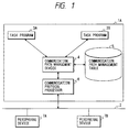
- Fig. 1 is a block diagram of a data transmission apparatus in accordance with a preferred embodiment of the present invention.
- Fig. 2 illustrates a record structure of a communication path management table in the data transmission apparatus of Fig. 1.
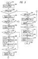
- Fig. 3 is a flow chart illustrating the operation of a communication path management device in the data transmission apparatus of Fig. 1.
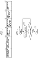
- Fig. 4 is a flow chart illustrating a data transmission sequence by a task program device in the data transmission apparatus of Fig. 1.
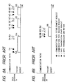
- Figs. 5A and 5B illustrate a timing chart showing how the communication path management device automatically establishes/releases a communication path in response to a data transmission request from the task program device in the data transmission apparatus of Fig. 1.
- Fig. 6 is a block diagram of a conventional data transmission apparatus.
- Fig. 7 is a flow chart illustrating a data transmission sequence by a task program in the data transmission apparatus of Fig. 6.
- Figs. 8A and 8B illustrate a timing chart depicting how the task program establishes/releases a communication path in the data transmission apparatus of Fig. 6.
- Fig. 1 shows a block diagram of a programmable data transmission apparatus 1A, which includes task program devices 3a, 3b, a communication management device 4 for managing the communication path or paths used by task program devices 3a, 3b, a communication path management table 5 for storing information necessary for the communication path management device 4 to manage the communication path, and a communication protocol processor 6.
- Fig. 2 shows the record structure of the communication path management table 5, which includes a recording area for a communication path number 21, a task program label 22, a peripheral device label 23, a communication path attribute 24, a communication path establishment time 25, a last communication time 26, and a communication count 27.
- the communication path management table 5 has a plurality of records, each record composed of the above recording areas, corresponding to a plurality of communication paths that the data transmission apparatus 1A can support.
- step S101 the communication path management device 4 initiates a data transmission operation.
- step S102 a communication path establishment request from one of the task program devices 3a, 3b, is sent to the communication path management device 4, which then retrieves management data from task program label recording area 22 and the peripheral device label recording area 23 in the communication path management table 5.
- step S103 the communication path management device 4 then determines whether a communication path has been established between the specified peripheral device and the requesting task program device. If it is determined that the communication path to the specified peripheral device has been established, then execution advances to step S115. If the communication path has not been established, then execution proceeds to step S104, where the management data in the communication path number recording area 21 of the communication path management table 5 is retrieved to check for a vacant communication path. In step S105, it is checked whether a vacant communication path currently exists in the data transmission apparatus 1A so that if a vacant path exists execution proceeds to step S113, otherwise execution continues on to step S106.
- the management data in the communication path attribute recording area 24 of the communication path management table 5 is retrieved to determine which one of a plurality of communication paths can be released and then established for the requesting task program device.
- attributes including the management data from the communication path management table 5 of each communication path is examined according to a predetermined algorithm (discussed in more detail below) to determine which communication path has releasable attributes, if any.
- step S107 the number of communication paths having releasable attributes is compared to 1. If there are more than 1 then execution advances to step S108, otherwise execution progresses to step S119.
- step S108 management data in the communication path establishment time recording area 25 and the communication count recording area 27 of the communication path management table 5 are analyzed in step S108.
- the communication path having the lowest frequency of use among the plurality of releasable communication paths is retrieved.
- the manner in which the frequency of use is calculated is as follows: "communication count” - "communication path establishment time” "current time”. Other techniques can of course be used.
- step S108 If there are a plurality of releasable communication paths extracted in step S108, the management data in the last communication time recording area 26 of the communication path management table 5 is examined in step S109 to retrieve the releasable communication path which has not been used for the longest most recent period of time. Then, this communication path is released in step S110 and checked in step S111 as to whether the communication path has been released successfully. If the result of the step S110 is normal (successful), execution progresses to step S112. If the result indicates a fault (unsuccessful), then execution proceeds to step S119.
- step S110 management data relating to the communication path released in step S110 is deleted from the communication path management table 5 in step S112.
- the communication path leading to the peripheral device specified by the requesting task program device is established using the vacant communication path in step S113, and it is checked in step S114 whether the new communication path has been successfully established. Execution then proceeds to step S117 if the communication path is successfully established; otherwise (i.e., if a fault occurred) execution advances to step S119.
- management data relating to the communication path established in step S113 is stored in the communication path management table 5 in step S117. Data is then transmitted in step S118 to the peripheral device via the established communication path.
- step S119 one of
- step S115 If the examination of the established communication path is normal in step S115, execution proceeds to step S116, where the communication path management table 5 is updated by storing the current time in the last communication time recording area 26 and incrementing by one the communication count recording area 27. If the result is not normal, then execution proceeds to step S113, where another communication path is established.
- step S151 one of the task program devices 3a, 3b starts execution of the task program and outputs a data transmission request to the communication path management device 4, specifying a peripheral device, in step S152.
- the requesting task program device 3a, 3b then waits for the data transmission end notice from the communication path management device 4.
- the requesting task program device Upon receiving the data transmission end notice from the communication path management device 4, the requesting task program device checks the contents of the data transmission end notice in step S153. If data transmission is successful, the execution advances to step S154, where the processing is terminated. If it has failed, execution returns to step S152 to repeat the above steps.
- a second example is provided with reference to the timing charts of Figs. 5A and 5B illustrates how the task program devices 3a and 3b share a single communication path and transmit data.
- the task program device 3a issues a data transmission request 11a and then transmits data.
- the task program device then waits for a data transmission end notice 12a, which signifies the end of the data transmission operation.
- This data transmission sequence is identical to the sequence described with reference to the flow chart of Fig. 4.
- the task program device 3a, 3b need only output the data transmission request to the communication path management device 4 and wait for the result. That is, the task program device 3a, 3b does not have to consider the state of any communication path. For example, if the communication path is abnormally released due to the influence of noise, for example, the communication path is automatically re-established by the communication path management device 4 when the task program device 3a, 3b outputs the data transmission request.
- the sequence of operations include:
- step S113 in the flow chart of Fig. 3 a communication path is established with a peripheral device requested by one of the task programs 3a, 3b.
- step S114 a determination is made whether the communication path has been established without fault. If it has, in this embodiment, step S117 is skipped and execution continues on to step S118, where data is transmitted to the specified peripheral device through the established communication path. Next, it is checked whether data transmission to the peripheral device has been successful. If successful, in this embodiment the above established communication path is immediately released without updating the communication path management table 5 and the execution advances to step S119. At step S119, the result of the data transmission in step S118 is output to the task programs 3a, 3b. Processing is then terminated at step S120.
- the communication path management table 5 is not updated and therefore it will not contain management data relating to communication paths whose frequency of use is extremely low.
- the judgment on low frequency of use can be made by path attributes which indicate that they are not frequently used and that, because of this, they do not have to be registered in the communication path management table 5.
- the path management table continues to indicate that a previous task has "rights" to a particular path, such that this path is effectively "defaulted” to the use of that task.
- task programs are processed in the data transmission apparatus by the task program devices 3a, 3b, it will be appreciated that the task program processing device and the communication path processing device from the communication path management device onward may be separated, mounted in different apparatus, and connected by a communication line such as a serial line (e.g., RS-232C).
- a communication line such as a serial line (e.g., RS-232C).
Landscapes
- Engineering & Computer Science (AREA)
- Computer Security & Cryptography (AREA)
- Computer Networks & Wireless Communication (AREA)
- Signal Processing (AREA)
- Computer And Data Communications (AREA)
- Communication Control (AREA)
Claims (14)
- Appareil (1) de transmission de données, pour transmettre sur plusieurs voies de transmission des données provenant de dispositifs à programme d'exécution (3A, 3B) inclus dans l'appareil de transmission de données, vers des dispositifs périphériques (7A, 7B), comprenant:un tableau (5) de gestion des voies de transmission, pour conserver des données de gestion correspondant à chaque voie de transmission établie entre lesdits dispositifs à programme d'exécution et lesdits dispositifs périphériques;un dispositif (4) de gestion des voies de transmission, pour récupérer lesdites données de gestion dans ledit tableau (5) de gestion des voies de transmission, en vue de sélectionner une voie de transmission en réponse à une demande d'établissement d'une voie de transmission vers un dispositif périphérique spécifié, provenant d'un dispositif (3A, 3B) à programme d'exécution ; etun processeur (6) de protocole de communication répondant à une sortie dudit dispositif (4) de gestion des voies de transmission, pour commander des communications entre lesdits dispositifs (3A, 3B) à programme d'exécution et lesdits dispositifs périphériques (7A, 7B) en établissant ladite voie de transmission sélectionnée entre ledit dispositif à programme d'exécution qui le demande et ledit dispositif périphérique spécifié.
- Appareil de transmission de données selon la revendication 1, dans lequel ledit tableau (5) de gestion des voies de transmission comprend un moyen pour conserver des données de gestion qui comprennent un numéro (21) de voie de transmission, une identification (22) du programme d'exécution, une identification (23) du dispositif périphérique, au moins un attribut (24) de la voie de transmission, un moment (25) d'établissement de la voie de transmission, un moment de fin de communication (26) et un comptage (27) de communication, lesdites données de gestion étant conservées pour chacune desdites plusieurs voies de transmission.
- Appareil de transmission de données selon la revendication 1, dans lequel ledit tableau (5) de gestion des voies de transmission comprend un moyen pour conserver des données de gestion concernant la fréquence d'utilisation de chaque voie de transmission et le moment auquel chaque voie de transmission a été utilisée pour la dernière fois.
- Appareil de transmission de données selon la revendication 1, dans lequel ledit dispositif (4) de gestion des voies de transmission comprend: un moyen pour déterminer, si une voie de transmission n'est pas déjà établie entre le programme d'exécution demandeur et le dispositif périphérique demandé, si une voie de transmission est libre; et un moyen pour déterminer, si une voie de transmission n'est pas libre, une voie de transmission présentant des attributs qui peuvent être libérés, dans lequel ledit dispositif de gestion des voies de transmission sélectionne ladite voie de transmission libre si elle est disponible, et une voie de transmission présentant des attributs libérables si aucune voie de transmission n'est libre.
- Procédé de gestion de voies de transmission pour un appareil de transmission de données servant à transmettre, par plusieurs voies de transmission, des données provenant de dispositifs à programme d'exécution inclus dans l'appareil de transmission de données, vers des dispositifs périphériques, comprenant les étapes consistant à:demander une voie de transmission vers un dispositif périphérique spécifié, en vue de transmettre des données;récupérer des données de gestion conservées dans un tableau de gestion des voies de transmission et déterminer, sur base desdites données de gestion, si une voie de transmission vers ledit dispositif périphérique spécifié est déjà établie; etétablir une voie de transmission vers ledit dispositif périphérique spécifié si une voie de transmission vers ledit dispositif périphérique spécifié n'est pas déjà établie.
- Procédé de gestion de voies de transmission selon la revendication 5, qui comprend en outre l'étape consistant à mettre à jour ledit tableau de gestion des voies de transmission avec des données de gestion qui correspondent à ladite voie de transmission établie utilisée pour transférer des données vers ledit dispositif périphérique spécifié.
- Procédé de gestion de voies de transmission selon la revendication 5, comprenant en outre une étape consistant à sélectionner une voie de transmission vers ledit dispositif périphérique spécifié lorsqu'une voie de transmission n'est pas déjà établie.
- Procédé de gestion de voies de transmission selon la revendication 7, dans lequel ladite étape consistant à sélectionner une voie de transmission comprend les étapes consistant à:déterminer si une voie de transmission est libre et, si c'est le cas, sélectionner ladite voie de transmission libre;si une voie de transmission n'est pas libre, sélectionner une voie de transmission présentant des attributs libérables; etlibérer ladite voie de transmission sélectionnée.
- Procédé de gestion de voies de transmission selon la revendication 8, dans lequel ladite étape consistant à sélectionner une voie de transmission présentant des attributs libérables comprend les étapes consistant à:déterminer le nombre des voies de transmission qui présentent des attributs libérables; ets'il existe plus d'une voie de transmission qui présente des attributs libérables, sélectionner parmi les voies de transmission qui présentent des attributs libérables, une voie de transmission qui présente la fréquence d'utilisation la plus basse.
- Procédé de gestion de voies de transmission selon la revendication 8, dans lequel ladite étape consistant à sélectionner une voie de transmission présentant des attributs libérables comprend les étapes consistant à:déterminer le nombre des voies de transmission qui présentent des attributs libérables; ets'il existe plus d'une voie de transmission qui présente des attributs libérables, sélectionner parmi les voies de transmission présentant des attributs libérables, une voie de transmission qui n'a pas été établie pendant la plus longue durée la plus récente.
- Procédé de gestion de voies de transmission selon la revendication 7, dans lequel ladite étape consistant à sélectionner une voie de transmission comprend les étapes consistant à:déterminer si une voie de transmission est libre et, si c'est le cas, sélectionner ladite voie de transmission libre;si une voie de transmission n'est pas libre, sélectionner une voie de transmission présentant des attributs libérables;libérer ladite voie de transmission sélectionnée; etmettre à jour ledit tableau de gestion des voies de transmission avec des données de gestion qui correspondent à ladite voie de transmission qui présente des attributs libérables et qui a été sélectionnée.
- Procédé de gestion de voies de transmission selon la revendication 5, comprenant en outre l'étape consistant à libérer ladite voie de transmission établie, immédiatement après que les données aient été transférées vers ledit dispositif périphérique spécifié.
- Procédé de gestion de voies de transmission selon la revendication 9, comprenant en outre l'étape consistant à sélectionner, s'il existe plusieurs voies de transmission qui présentent la plus basse fréquence d'utilisation, une voie de transmission qui n'a pas été établie pendant la plus longue durée la plus récente.
- Procédé de gestion de voies de transmission selon la revendication 8, dans lequel, lorsqu'une voie de transmission vers le dispositif périphérique requis n'a pas encore été établie, on établit une première voie de transmission en provoquant la libération d'une première voie de transmission sélectionnée, et en effectuant ensuite des communications en utilisant ladite première voie de transmission sélectionnée; et on libère ensuite la première voie de transmission sélectionnée sans mettre à jour le tableau de gestion de voies de transmission en ce qui concerne les données de gestion relatives à ladite première voie de transmission.
Priority Applications (2)
| Application Number | Priority Date | Filing Date | Title |
|---|---|---|---|
| EP93103472A EP0622927B1 (fr) | 1993-03-04 | 1993-03-04 | Appareil de transmission de données et méthode de gestion de chemin de communication |
| DE69311307T DE69311307T2 (de) | 1993-03-04 | 1993-03-04 | Datenübertragungsgerät und Verfahren zur Verwaltung des Übertragungsweges |
Applications Claiming Priority (1)
| Application Number | Priority Date | Filing Date | Title |
|---|---|---|---|
| EP93103472A EP0622927B1 (fr) | 1993-03-04 | 1993-03-04 | Appareil de transmission de données et méthode de gestion de chemin de communication |
Publications (2)
| Publication Number | Publication Date |
|---|---|
| EP0622927A1 EP0622927A1 (fr) | 1994-11-02 |
| EP0622927B1 true EP0622927B1 (fr) | 1997-06-04 |
Family
ID=8212660
Family Applications (1)
| Application Number | Title | Priority Date | Filing Date |
|---|---|---|---|
| EP93103472A Expired - Lifetime EP0622927B1 (fr) | 1993-03-04 | 1993-03-04 | Appareil de transmission de données et méthode de gestion de chemin de communication |
Country Status (2)
| Country | Link |
|---|---|
| EP (1) | EP0622927B1 (fr) |
| DE (1) | DE69311307T2 (fr) |
Family Cites Families (3)
| Publication number | Priority date | Publication date | Assignee | Title |
|---|---|---|---|---|
| US4191941A (en) * | 1978-04-03 | 1980-03-04 | Rca Corporation | Switch matrix for data transfers |
| US4621357A (en) * | 1984-08-16 | 1986-11-04 | At&T Bell Laboratories | Time division switching system control arrangement and method |
| JP2703391B2 (ja) * | 1990-06-18 | 1998-01-26 | 株式会社東芝 | ブリッジ装置 |
-
1993
- 1993-03-04 EP EP93103472A patent/EP0622927B1/fr not_active Expired - Lifetime
- 1993-03-04 DE DE69311307T patent/DE69311307T2/de not_active Expired - Fee Related
Also Published As
| Publication number | Publication date |
|---|---|
| DE69311307D1 (de) | 1997-07-10 |
| EP0622927A1 (fr) | 1994-11-02 |
| DE69311307T2 (de) | 1997-10-23 |
Similar Documents
| Publication | Publication Date | Title |
|---|---|---|
| US5511169A (en) | Data transmission apparatus and a communication path management method therefor | |
| JP3382953B2 (ja) | 有限メモリコンピュータシステム上におけるクライアント管理フロー制御方法及び装置 | |
| EP1615378B1 (fr) | Nms avec traitement d'evenements par multi-serveur | |
| US6041049A (en) | Method and apparatus for determining a routing table for each node in a distributed nodal system | |
| US6748413B1 (en) | Method and apparatus for load balancing of parallel servers in a network environment | |
| US5949977A (en) | Method and apparatus for requesting and processing services from a plurality of nodes connected via common communication links | |
| US5825775A (en) | Method and apparatus for managing an integrated router/hub | |
| US5781737A (en) | System for processing requests for notice of events | |
| US7676610B2 (en) | Device and method for optimization of target host device process handling according to the status and the priority of the target host device process | |
| EP0950952A2 (fr) | Gestion de la charge de travail des serveurs dans un système d'ordinateurs client/serveur asynchrone | |
| JPH09186688A (ja) | 改善されたノードディスカバリ及び監視付きネットワーク管理システム | |
| US5768524A (en) | Method for processing requests for notice of events | |
| US20050038888A1 (en) | Method of and apparatus for monitoring event logs | |
| EP0769863B1 (fr) | Dispositif de pontage pour filtrage de circulation dans des réseaux de communication | |
| EP1002414A1 (fr) | Systeme et procede de mise en file d'attente pour le transfert de messages point a point | |
| US6041342A (en) | Low traffic network management method using estimated process execution time for manager-agent synchronization | |
| EP1589424A2 (fr) | Cadre à périmètre vertical pour fournir des services d'application dans des environements multi-processeurs | |
| US6154129A (en) | Operation system for transmission devices and alarm monitoring method | |
| EP0622927B1 (fr) | Appareil de transmission de données et méthode de gestion de chemin de communication | |
| JP4673532B2 (ja) | マルチマネージャ環境における包括アライメントプロセス | |
| EP0729253A2 (fr) | Méthode d'effaçage d'objets gérés dans un réseau | |
| US6532478B1 (en) | File loader in information processing system of multiprocessor configuration | |
| JP2000047890A (ja) | 分散オブジェクト管理システムとそのオブジェクト選択方法およびその処理プログラムを記録した記録媒体 | |
| CN111343101B (zh) | 服务器限流方法、装置、电子设备及可读存储介质 | |
| WO2007100413A2 (fr) | Interopérabilité entre porteuses pour services critiques |
Legal Events
| Date | Code | Title | Description |
|---|---|---|---|
| PUAI | Public reference made under article 153(3) epc to a published international application that has entered the european phase |
Free format text: ORIGINAL CODE: 0009012 |
|
| 17P | Request for examination filed |
Effective date: 19931209 |
|
| AK | Designated contracting states |
Kind code of ref document: A1 Designated state(s): DE SE |
|
| GRAG | Despatch of communication of intention to grant |
Free format text: ORIGINAL CODE: EPIDOS AGRA |
|
| 17Q | First examination report despatched |
Effective date: 19960905 |
|
| GRAH | Despatch of communication of intention to grant a patent |
Free format text: ORIGINAL CODE: EPIDOS IGRA |
|
| GRAH | Despatch of communication of intention to grant a patent |
Free format text: ORIGINAL CODE: EPIDOS IGRA |
|
| GRAA | (expected) grant |
Free format text: ORIGINAL CODE: 0009210 |
|
| AK | Designated contracting states |
Kind code of ref document: B1 Designated state(s): DE SE |
|
| REF | Corresponds to: |
Ref document number: 69311307 Country of ref document: DE Date of ref document: 19970710 |
|
| PLBE | No opposition filed within time limit |
Free format text: ORIGINAL CODE: 0009261 |
|
| STAA | Information on the status of an ep patent application or granted ep patent |
Free format text: STATUS: NO OPPOSITION FILED WITHIN TIME LIMIT |
|
| 26N | No opposition filed | ||
| PGFP | Annual fee paid to national office [announced via postgrant information from national office to epo] |
Ref country code: DE Payment date: 20000228 Year of fee payment: 8 |
|
| PGFP | Annual fee paid to national office [announced via postgrant information from national office to epo] |
Ref country code: SE Payment date: 20000307 Year of fee payment: 8 |
|
| PG25 | Lapsed in a contracting state [announced via postgrant information from national office to epo] |
Ref country code: SE Free format text: LAPSE BECAUSE OF NON-PAYMENT OF DUE FEES Effective date: 20010305 |
|
| EUG | Se: european patent has lapsed |
Ref document number: 93103472.2 |
|
| PG25 | Lapsed in a contracting state [announced via postgrant information from national office to epo] |
Ref country code: DE Free format text: LAPSE BECAUSE OF NON-PAYMENT OF DUE FEES Effective date: 20020101 |