EP0622603A1 - Tube de lancement à propulsion multi-étages de projectiles - Google Patents
Tube de lancement à propulsion multi-étages de projectiles Download PDFInfo
- Publication number
- EP0622603A1 EP0622603A1 EP94302116A EP94302116A EP0622603A1 EP 0622603 A1 EP0622603 A1 EP 0622603A1 EP 94302116 A EP94302116 A EP 94302116A EP 94302116 A EP94302116 A EP 94302116A EP 0622603 A1 EP0622603 A1 EP 0622603A1
- Authority
- EP
- European Patent Office
- Prior art keywords
- tube
- charges
- interior
- housing
- propulsion
- Prior art date
- Legal status (The legal status is an assumption and is not a legal conclusion. Google has not performed a legal analysis and makes no representation as to the accuracy of the status listed.)
- Withdrawn
Links
Images


Classifications
-
- F—MECHANICAL ENGINEERING; LIGHTING; HEATING; WEAPONS; BLASTING
- F41—WEAPONS
- F41A—FUNCTIONAL FEATURES OR DETAILS COMMON TO BOTH SMALLARMS AND ORDNANCE, e.g. CANNONS; MOUNTINGS FOR SMALLARMS OR ORDNANCE
- F41A1/00—Missile propulsion characterised by the use of explosive or combustible propellant charges
- F41A1/02—Hypervelocity missile propulsion using successive means for increasing the propulsive force, e.g. using successively initiated propellant charges arranged along the barrel length; Multistage missile propulsion
Definitions
- the present invention relates to apparatus for accelerating a projectile in a tube, such as might be used in a tube launched rocket system which includes a plurality of small propellant charges located within the tube which propel the rocket by thrusting gases into a travelling propulsion chamber.
- tube launched weapon system such as conventional anti-aircraft and anti-tank weaponry.
- These systems generally involve the firing of a projectile which utilizes a rocket motor for propulsion.
- the rocket propelled projectile is launched from an open tube.
- these devices are classified as open breech devices, as opposed to rifles, howitzers and the like which launch a projectile from a tube having one closed end.
- Tube launched weapon systems are very important in modern military operations. A foot soldier using these systems can deliver much larger quantities of explosive force than was possible using conventional closed breech infantry weapons.
- anti-tank and anti-aircraft missiles can be launched using a tube system supported by a man's shoulder. Because the aft end of the tube is open, recoil from the rocket motor is manageable, and there is no need to construct massive recoil absorption systems such as those found on a howitzer.
- Tube launched weapon systems face several significant design problems.
- the projectile launched by the system includes a rocket motor for propulsion. It is critical that the motor completely burn out before it leaves the tube; if the rocket motor is still burning when it exits the tube, the hot exhaust may severely injure the system's user.
- the propellant in the rocket motor must burn extremely rapidly but still provide maximal forward thrust.
- the propellant must be designed to perform properly under a wide range of ambient conditions.
- the propellant function equally well at sea level and at high altitudes, in extreme heat and extreme cold, in jungle humidity and in arid desert air. It will be appreciated, however, that designing the propellant to burn out before exit under such extreme conditions results in a rocket motor that provides less than optimal performance under most circumstances.
- the sound wave is large enough that it presents a significant safety concern.
- the sound wave itself has the potential of causing injury or death to the user. Accordingly, it is now conventional for the user to wear ear plugs, ear muffs, and a helmet.
- the pressure and sound waves caused by the launch of tube launched rocket motors are such that it is not possible to safely operate the device within a building. Such operation may damage the building and endanger the occupants of the building. This limitation is significant in that there are often situations where use of such devices within a building would be desirable.
- the invention provides apparatus for accelerating a projectile in a tube, the projectile having a forward and an aft end, the tube having a forward end, an aft end and an interior, the apparatus comprising:
- the present invention thus provides a tube launched weapon system in which a propulsion housing which travels through the tube directly behind the projectile being launched.
- the propulsion housing is not powered by a rocket motor contained in the projectile. Rather, the projectile is accelerated by a sequence of relatively small propellant charges disposed along the interior of the tube. The charges form part of the outer wall of a propulsion chamber.
- the rest of the chamber is defined by a propulsion housing.
- the housing includes a forward plate, which abuts the projectile, and an aft nozzle for venting gases from the interior of the chamber.
- the forward plate and the nozzle are secured to one another by a restraining member having slots.
- the housing may contain one or more baffles for directing the flow of gases.
- the apparatus can include an electronic ignition system having a power supply, a controller, and a wire electrically connecting the charges to the power supply for appropriate ignition under the controller's direction.
- Each propellant charge is relatively small, but ignition of the charges in proper sequence provides adequate thrust to the propulsion housing and hence to the projectile.
- Each charge can be made relatively small, which permits the use of charges composed of relatively non-toxic materials, such as metal azide compositions, without unacceptable sacrifices in projectile range. Moreover, smaller charges fired in sequence result in a stair-stepping increase in pressure over time. Because pressure increases cause significant noise, the gradual pressure increase created by the present invention is preferable to the single large increase over a very short time caused by previously disclosed systems based on rocket motors located in the projectile.
- An additional advantage is inherent in the use of charges disposed along the interior of the tube rather than attached to the projectile. There is no risk of burns to the user from a projectile's rocket motor back blast because the projectile contains no rocket motor. Projectile burn out under a wide range of environmental conditions is no longer a design constraint, because the projectile never burns; all ignitions occur inside the tube.
- closed breech devices may also benefit from the present invention of a travelling fixed size propulsion chamber powered by charges attached to the barrel.
- Use of charges attached to a barrel closed at one end to accelerate a projectile through the barrel toward the open end is known in the art.
- the propulsion chamber in such known devices is effectively formed by the charges, the walls of the barrel, the closed end of the barrel, and the aft end of the projectile. Since the aft end of the projectile and the closed end of the barrel are clearly not connected, the propulsion chamber grows in volume as the projectile moves through the barrel. It is therefore necessary to use increasingly powerful charges as the chamber grows in volume in order to obtain the same acceleration.
- the propulsion chamber has a fixed size. Consequently, one need not employ successively more powerful propulsion charges as the projectile moves.
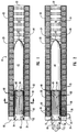
- Figure 1 shows apparatus 10 in longitudinal cross section which comprises a tube 20.
- a plurality of propellant charges 30 are located along the interior 26 of the tube 20.
- the charges 30 are toroidal in shape, and are placed along the interior of the tube 20 so as to form a tubular structure having an open interior 26.
- Figure 1 shows a complete projectile 40 and propulsion housing 50 in the tube 20 at their initial position before ignition.
- the aft end 54 of the propulsion housing 50 is near the aft end 24 of the tube 20.
- the forward end 52 of the propulsion housing 50 abuts the aft end 44 of the projectile 40, and the forward end 42 of the projectile points toward the forward end 22 of the tube 20.
- a restraining member with attached baffles 68 connects the forward plate 60 and the nozzle 62.
- Figure 6 shows the restraining member 66 and baffles 68 of the Figure 1 embodiment in cross section.
- the alternative embodiment of the propulsion housing illustrated in Figure 7 has no baffles but employs as a restraining member a cylindrical housing 53 having slots 58.
- the portion of the interior 26 of the charges 30 which lies between the forward plate 60 and the nozzle 62 of the propulsion housing 50 forms the interior 56 of the propulsion housing 50.
- the charges 30, the nozzle 62, the restraining member, and the forward plate 60 define a propulsion chamber whose volume remains substantially constant as the projectile 40 travels through the tube 20.
- tubes of equal diameters but varying lengths may be attached to one another in end-to-end fashion, thereby providing users with control over the total number of charges employed to launch a given projectile.
- users may conserve munitions by utilizing tubes having fewer charges when lesser projectile ranges are adequate, and utilizing longer tubes having more charges only when greater projectile ranges are required.
- An extension tube 28 has been attached to the forward end 22 of the original tube 20.
- An extension tube attachment apparatus 29 physically secures the extension tube 28 to the original tube 20.
- Wire connectors 85 serve to extend the electronic ignition system.
- an electronic ignition system is used to ignite the charges 30 and propel the projectile 40 out the forward end 22 of the tube 20.
- the electronic ignition system comprises an electrical power supply 80, an ignition controller 82, and a wire 84.
- the wire 84 is shown in Figure 6, as well as in Figure 1.
- embodiments employing propellant charges 30 which are not directly ignitable electronically may also comprise an igniter 86.
- Various igniters, such as BKNO3, are known in the art.
- the ignition controller 82 Upon receipt of a command from the user, the ignition controller 82 releases electrical energy through the wire 84 into the igniters 86 in sequence, thereby igniting the charges 30 in sequence. Gases released by the combusting charges 30 propel the projectile 40 through the tube 20 in a fashion described below.
- the charges are preferably ignited in sequence, beginning with charges adjacent to the interior 56 of the propulsion housing 50 at the aft end 24 of the tube 20. Rapidly expanding gases 36 created by igniting the charges flow into the interior 56 of the propulsion housing 50.
- each charge 30 is surrounded by a charge casing 32 having ports 34 that direct the gases 36 inward toward the central longitudinal axis 72 of the propulsion housing 50.
- the gases 36 thus are directed into a propulsion chamber defined essentially by the charges 30, the forward plate 60 of the propulsion housing 50, and the nozzle 62 of the propulsion housing 50.
- Seals 70 may be employed at the ends of the propulsion housing 50 to reduce leakage of the gases 36.
- the gases 36 pass backwards through the nozzle throat 64 and drive the propulsion housing 50 forward, according to the action-reaction principle of physics.
- the forward plate of the propulsion housing 50 abuts the aft end 44 of the projectile 40, so the gases 36 driving the housing 50 likewise drive the projectile 40 forward.
- these exhaust gases may be relatively non-toxic.
- the present invention employs a sequence of smaller propellant charges instead of a rocket motor, the charges may be composed of less explosive yet less toxic materials.
- One such material is a composition of metal azide, such as sodium azide, which is known in the art.
- FIG 3 shows an alternative embodiment which is similar to the apparatus of Figures 1 and 2 but employs baffles 69 arranged helically about the central longitudinal axis 72 of the propulsion housing 50.
- the housing 50 and projectile 40 are shown in their positions after a number of the propellant charges 30 have been ignited and expended substantially all of the resulting rapidly expanding gases. These burned out propellant charges are indicated by substantially empty charge casings 32, although some particulate material or other residue may remain in the casing after burn out.
- Other charges 30, being aligned with the propulsion housing 50 are still expelling gases 36 into the propulsion chamber in the interior 56 of the propulsion housing 50. Charges near the front end 22 of the tube 20 have not yet been ignited because they are not yet aligned with the propulsion housing 50.
- closed breech devices may employ sequentially ignited charges along the interior of a tube to propel a fixed-size propulsion chamber through the tube. Closed breech devices may thereby obtain the reduced noise levels and other advantages of the present invention. Closed breech devices employing the present invention would include recoil management systems and other necessary components known in the art.
- Figure 4 shows the projectile 40 and propulsion housing 50 of Figures 1 and 2 immediately after they exit the forward end 22 of the tube 20. All the charges 30 have been ignited.
- the charges 30 are contained inside the tube 20 rather than in the projectile 40.
- the projectile 40 itself does not emit exhaust gases when launched.
- the pressure wave produced by the charges grows relatively slowly in comparison to the pressure waves of conventional tube launched weapon rocket motor systems.
- the noise produced by the present invention is more manageable than in previous systems.
- the propulsion housing is secured to the projectile, so the projectile and housing fly together toward the intended target.
- the propulsion housing 51 separates from the projectile 40 and drops to the ground some distance beyond the forward end 22 of the tube 20, while the projectile continues on toward the target.
- the embodiment of Figure 5 provides increased range for the projectile by decreasing the mass in flight by detaching the propulsion housing. Care must be taken, however, to ensure that the separation of the propulsion housing 51 from the projectile 40 does not alter the projectile's intended flight path.
- Figure 6 shows a transverse cross sectional view, taken along the line 6-6 of Figure 1.
- the tube 20 is circular in cross section, and the charges 30 are toroidal.
- the charges 30 form a tubular structure having an open interior.
- the portion of the interior of the charge structure which lies between the forward plate and the nozzle of the propulsion housing forms the interior 56 of the propulsion housing.
- the charge 30 is enclosed within a charge casing 32 provided with ports 34, so that when the charge 30 is ignited, the resulting rapidly expanding gases are directed toward the interior 56 of the propulsion housing.
- Planar baffles 68 direct the expanding gases toward the forward and aft ends of the propulsion housing.
- the gas pressure developed from combustion of a propellant increases as a function of the combusting surface area.
- One method of increasing the combustible surface area of the present invention would be to lengthen the propulsion housing; another would be to increase the inside diameter of the toroidal charges which form part of the outer wall of the propulsion chamber.
- the alternative embodiment shown in Figure 7 illustrates a third possibility.
- the charges 31 forming the wall of the propulsion chamber have grooves 33 such that the interior 56 of the propulsion chamber is star-shaped.
- the grooves 33 provide greater charge surface area, and thereby provide a greater combustible surface area.
- the grooves provide a greater volume of combustion gases per unit of time after ignition of the charge 31 than the embodiment of Figure 6.
- a restraining member 66 may be employed to secure the nozzle of the propulsion housing to the forward plate.
- An alternative embodiment of the restraining member including a cylinder 53 having slots 58 is shown in Figure 7.
- the charges, the nozzle, and the forward plate define a propulsion chamber whose volume remains substantially constant as the projectile travels through the tube.
- this constant volume permits the same acceleration to be imparted by charges of equal explosive power located at different points along the tube.
- the propulsion chamber increases in volume as the projectile moves, so that gas compressibility decreases the effective force of later ignited charges as compared to earlier ignited charges.
- the present invention provides a tube launched weapon system in which the requirement of protecting users from rocket motor exhaust burns is not a significant constraint on propellant composition. Because the propellant charges lie within the tube rather than being attached to the projectile, there is no danger that exhaust from an exiting projectile will burn the user. Propellants can therefore be chosen to maximize their performance in a wide range of environments without increasing the risk to users.
- the invention provides a high-performance tube launched weapon system that produces manageable levels of noise.
- the present invention creates a pressure wave that increases in steps over time.
- the pressure wave of conventional systems by contrast, rises rapidly to its peak over a very short time, and therefore produces pressure waves that severely restrict the circumstances in which conventional systems may safely be used.
- the present invention provides a tube launched weapon system capable of imparting adequate forward thrust to a projectile through the use of a relatively non-toxic propellant.
- Each charge can be composed of metal azides or other compositions not commonly used in conventional rocket motors, because the charges act in sequence over time. Additional charges may also be added in a modular fashion. Thus, users may conserve munitions by utilizing tubes having fewer charges when lesser projectile ranges are adequate, and utilizing longer tubes having more charges only when greater projectile ranges are required.
Landscapes
- Engineering & Computer Science (AREA)
- Chemical & Material Sciences (AREA)
- Combustion & Propulsion (AREA)
- General Engineering & Computer Science (AREA)
- Aiming, Guidance, Guns With A Light Source, Armor, Camouflage, And Targets (AREA)
Applications Claiming Priority (2)
| Application Number | Priority Date | Filing Date | Title |
|---|---|---|---|
| US08/056,426 US5322002A (en) | 1993-04-30 | 1993-04-30 | Tube launched weapon system |
| US56426 | 1993-04-30 |
Publications (1)
| Publication Number | Publication Date |
|---|---|
| EP0622603A1 true EP0622603A1 (fr) | 1994-11-02 |
Family
ID=22004337
Family Applications (1)
| Application Number | Title | Priority Date | Filing Date |
|---|---|---|---|
| EP94302116A Withdrawn EP0622603A1 (fr) | 1993-04-30 | 1994-03-24 | Tube de lancement à propulsion multi-étages de projectiles |
Country Status (2)
| Country | Link |
|---|---|
| US (1) | US5322002A (fr) |
| EP (1) | EP0622603A1 (fr) |
Families Citing this family (10)
| Publication number | Priority date | Publication date | Assignee | Title |
|---|---|---|---|---|
| US5503081A (en) * | 1993-11-22 | 1996-04-02 | Fmc Corp | Annular plasma injector |
| SE509310C2 (sv) * | 1994-06-17 | 1999-01-11 | Foersvarets Forskningsanstalt | Sätt att elektriskt initiera och styra förbränningen av en kompakt drivladdning samt drivladdning |
| US5841058A (en) * | 1996-01-26 | 1998-11-24 | Manis; John Robert | Firearms |
| US7040212B1 (en) * | 1996-08-09 | 2006-05-09 | Mbda Uk Limited | Launching missiles |
| US6032567A (en) * | 1998-03-16 | 2000-03-07 | The United States Of America As Represented By The Secretary Of The Navy | Surf zone mine clearance |
| US6668699B2 (en) * | 1998-08-20 | 2003-12-30 | Ronnie David Russell | Porous nozzle projectile barrel |
| US6584924B2 (en) * | 2001-02-13 | 2003-07-01 | The United States Of America As Represented By The Secretary Of The Navy | Apparatus for controlling pressure recovery |
| US6446535B1 (en) | 2001-02-16 | 2002-09-10 | The United States Of America As Represented By The Secretary Of The Navy | Triple-tube, dispersible countermass recoilless projectile launcher system |
| US7464634B1 (en) * | 2006-04-21 | 2008-12-16 | Lockheed Martin Corporation | Cold launch system comprising shape-memory alloy actuator |
| US11041692B1 (en) * | 2020-05-12 | 2021-06-22 | Michael Chromych | System and method for launching and acceleration of objects |
Citations (2)
| Publication number | Priority date | Publication date | Assignee | Title |
|---|---|---|---|---|
| US3031933A (en) * | 1960-11-04 | 1962-05-01 | Werner K Kern | Explosive linear acceleration |
| US4938112A (en) * | 1984-06-22 | 1990-07-03 | Washington Research Foundation | Apparatus and method for the acceleration of projectiles to hypervelocities |
Family Cites Families (15)
| Publication number | Priority date | Publication date | Assignee | Title |
|---|---|---|---|---|
| US200740A (en) * | 1878-02-26 | Improvement in accelerating-guns | ||
| US484011A (en) * | 1892-10-11 | hxskell | ||
| US1380358A (en) * | 1920-03-24 | 1921-06-07 | Charles J Cooke | Non-recoil gun |
| US2360217A (en) * | 1941-06-20 | 1944-10-10 | Francis Louis | Multicharge gun |
| US2397800A (en) * | 1944-03-20 | 1946-04-02 | Graham S Mcarthur | Gun |
| US3129636A (en) * | 1960-09-28 | 1964-04-21 | Aircraft Armaments Inc | Means for launching projectiles |
| DE977818C (de) * | 1963-06-22 | 1970-12-17 | Messerschmitt Boelkow Blohm | Treibladungsanordnung fuer rohrfoermige Abschusseinrichtungen |
| US3814694A (en) * | 1971-08-09 | 1974-06-04 | Aerojet General Co | Non-toxic gas generation |
| DE2236175C3 (de) * | 1972-07-24 | 1975-07-10 | Bayern-Chemie Gesellschaft Fuer Flugchemische Antriebe Mbh, 8261 Aschau | Treibmittel zur Erzeugung ungiftiger Treibgase |
| US3857321A (en) * | 1973-07-30 | 1974-12-31 | Subcom Inc | Submarine missile launch system |
| FR2316572A2 (fr) * | 1975-07-02 | 1977-01-28 | Europ Propulsion | Dispositif de lancement d'un projectile |
| US4157054A (en) * | 1978-03-17 | 1979-06-05 | The United States Of America As Represented By The Secretary Of The Army | Hypervelocity rocket system with velocity amplifier |
| US5033355A (en) * | 1983-03-01 | 1991-07-23 | Gt-Device | Method of and apparatus for deriving a high pressure, high temperature plasma jet with a dielectric capillary |
| US4590842A (en) * | 1983-03-01 | 1986-05-27 | Gt-Devices | Method of and apparatus for accelerating a projectile |
| US5053087A (en) * | 1990-03-02 | 1991-10-01 | Rockwell International Corporation | Ultra high-energy azide containing gun propellants |
-
1993
- 1993-04-30 US US08/056,426 patent/US5322002A/en not_active Expired - Fee Related
-
1994
- 1994-03-24 EP EP94302116A patent/EP0622603A1/fr not_active Withdrawn
Patent Citations (2)
| Publication number | Priority date | Publication date | Assignee | Title |
|---|---|---|---|---|
| US3031933A (en) * | 1960-11-04 | 1962-05-01 | Werner K Kern | Explosive linear acceleration |
| US4938112A (en) * | 1984-06-22 | 1990-07-03 | Washington Research Foundation | Apparatus and method for the acceleration of projectiles to hypervelocities |
Also Published As
| Publication number | Publication date |
|---|---|
| US5322002A (en) | 1994-06-21 |
Similar Documents
| Publication | Publication Date | Title |
|---|---|---|
| JP3670661B2 (ja) | 銃身アセンブリ | |
| EP1851501B1 (fr) | Procedes et appareils pour systeme de projectiles a vitesse selectionnable | |
| IL186114A (en) | Bullet to Kill equipped with a rocket cruiser | |
| KR20020091832A (ko) | 발사체 | |
| US5322002A (en) | Tube launched weapon system | |
| US3620162A (en) | Rifle launched rocket | |
| US5639982A (en) | Means to fire a fully automatic gun underwater using a special barrel clearance blank round | |
| RU2079096C1 (ru) | Боеприпас для ствольных систем | |
| RU2362960C2 (ru) | Патрон для нескольких метаемых тел | |
| JP4371820B2 (ja) | カウンターマス火器 | |
| US2681619A (en) | Rocket projectile | |
| US4553480A (en) | No flash, very low noise howitzer round and tube | |
| US4073213A (en) | Assembly for launching a projectile | |
| US4047465A (en) | Telescoped explosive driver | |
| US8122828B2 (en) | Cartridge for a firearm | |
| EP1337750B1 (fr) | Procede et dispositif destines a une roquette a plusieurs etages | |
| US3859890A (en) | Traveling tube ejector system | |
| US20210262756A1 (en) | Rocket armament launchable from a tubular launcher with an outside launcher non-ignition securing and motor separation during flight | |
| US4484524A (en) | Projectile for recoilless weapon | |
| RU2777720C2 (ru) | Пуля с реактивной отстреливаемой гильзой | |
| RU2117235C1 (ru) | Импульсный реактивный снаряд | |
| RU2099667C1 (ru) | Патрон с реактивной проникающей частью | |
| RU2202081C2 (ru) | Ручной гранатомет | |
| RU2217680C1 (ru) | Гранатомет на взрывном трубчатом ускорителе | |
| RU2217618C1 (ru) | Двигатель для выстреливаемой из гранатомета гранаты |
Legal Events
| Date | Code | Title | Description |
|---|---|---|---|
| PUAI | Public reference made under article 153(3) epc to a published international application that has entered the european phase |
Free format text: ORIGINAL CODE: 0009012 |
|
| AK | Designated contracting states |
Kind code of ref document: A1 Designated state(s): DE FR GB SE |
|
| STAA | Information on the status of an ep patent application or granted ep patent |
Free format text: STATUS: THE APPLICATION IS DEEMED TO BE WITHDRAWN |
|
| 18D | Application deemed to be withdrawn |
Effective date: 19950503 |