EP0622585A1 - Image carrying devices - Google Patents
Image carrying devices Download PDFInfo
- Publication number
- EP0622585A1 EP0622585A1 EP94302920A EP94302920A EP0622585A1 EP 0622585 A1 EP0622585 A1 EP 0622585A1 EP 94302920 A EP94302920 A EP 94302920A EP 94302920 A EP94302920 A EP 94302920A EP 0622585 A1 EP0622585 A1 EP 0622585A1
- Authority
- EP
- European Patent Office
- Prior art keywords
- colour
- cap
- assembly
- translucent
- graphic image
- Prior art date
- Legal status (The legal status is an assumption and is not a legal conclusion. Google has not performed a legal analysis and makes no representation as to the accuracy of the status listed.)
- Ceased
Links
- 239000011888 foil Substances 0.000 claims description 36
- 239000011248 coating agent Substances 0.000 claims description 9
- 238000000576 coating method Methods 0.000 claims description 9
- PCHJSUWPFVWCPO-UHFFFAOYSA-N gold Chemical compound [Au] PCHJSUWPFVWCPO-UHFFFAOYSA-N 0.000 claims description 7
- 229910052737 gold Inorganic materials 0.000 claims description 7
- 239000010931 gold Substances 0.000 claims description 7
- 229910052709 silver Inorganic materials 0.000 claims description 7
- 239000004332 silver Substances 0.000 claims description 7
- 238000000149 argon plasma sintering Methods 0.000 claims 1
- 230000001419 dependent effect Effects 0.000 claims 1
- 239000010410 layer Substances 0.000 description 86
- 239000010408 film Substances 0.000 description 17
- 238000000034 method Methods 0.000 description 14
- 239000003086 colorant Substances 0.000 description 12
- 238000000465 moulding Methods 0.000 description 10
- 239000011347 resin Substances 0.000 description 10
- 229920005989 resin Polymers 0.000 description 10
- 229910052782 aluminium Inorganic materials 0.000 description 8
- XAGFODPZIPBFFR-UHFFFAOYSA-N aluminium Chemical compound [Al] XAGFODPZIPBFFR-UHFFFAOYSA-N 0.000 description 8
- 230000005540 biological transmission Effects 0.000 description 8
- 238000003856 thermoforming Methods 0.000 description 7
- BQCADISMDOOEFD-UHFFFAOYSA-N Silver Chemical compound [Ag] BQCADISMDOOEFD-UHFFFAOYSA-N 0.000 description 6
- 229920002799 BoPET Polymers 0.000 description 5
- 239000005041 Mylar™ Substances 0.000 description 5
- 230000003287 optical effect Effects 0.000 description 5
- 239000004033 plastic Substances 0.000 description 5
- PXHVJJICTQNCMI-UHFFFAOYSA-N Nickel Chemical compound [Ni] PXHVJJICTQNCMI-UHFFFAOYSA-N 0.000 description 4
- 239000000463 material Substances 0.000 description 4
- 239000011241 protective layer Substances 0.000 description 4
- 238000009825 accumulation Methods 0.000 description 3
- 239000000853 adhesive Substances 0.000 description 3
- 230000001070 adhesive effect Effects 0.000 description 3
- 230000004313 glare Effects 0.000 description 3
- 238000010329 laser etching Methods 0.000 description 3
- 238000004519 manufacturing process Methods 0.000 description 3
- 229910052751 metal Inorganic materials 0.000 description 3
- 239000002184 metal Substances 0.000 description 3
- 238000012216 screening Methods 0.000 description 3
- VYZAMTAEIAYCRO-UHFFFAOYSA-N Chromium Chemical compound [Cr] VYZAMTAEIAYCRO-UHFFFAOYSA-N 0.000 description 2
- RYGMFSIKBFXOCR-UHFFFAOYSA-N Copper Chemical compound [Cu] RYGMFSIKBFXOCR-UHFFFAOYSA-N 0.000 description 2
- RTAQQCXQSZGOHL-UHFFFAOYSA-N Titanium Chemical compound [Ti] RTAQQCXQSZGOHL-UHFFFAOYSA-N 0.000 description 2
- 239000003795 chemical substances by application Substances 0.000 description 2
- 229910052804 chromium Inorganic materials 0.000 description 2
- 239000011651 chromium Substances 0.000 description 2
- 229910052802 copper Inorganic materials 0.000 description 2
- 239000010949 copper Substances 0.000 description 2
- 238000010586 diagram Methods 0.000 description 2
- 230000000694 effects Effects 0.000 description 2
- 238000005530 etching Methods 0.000 description 2
- 238000001746 injection moulding Methods 0.000 description 2
- 229910052759 nickel Inorganic materials 0.000 description 2
- 239000003973 paint Substances 0.000 description 2
- 229920000728 polyester Polymers 0.000 description 2
- 238000006748 scratching Methods 0.000 description 2
- 230000002393 scratching effect Effects 0.000 description 2
- 229910001220 stainless steel Inorganic materials 0.000 description 2
- 239000010935 stainless steel Substances 0.000 description 2
- 239000010936 titanium Substances 0.000 description 2
- 229910052719 titanium Inorganic materials 0.000 description 2
- 238000012546 transfer Methods 0.000 description 2
- 239000002966 varnish Substances 0.000 description 2
- 239000004411 aluminium Substances 0.000 description 1
- 230000000712 assembly Effects 0.000 description 1
- 238000000429 assembly Methods 0.000 description 1
- 230000027455 binding Effects 0.000 description 1
- 238000009739 binding Methods 0.000 description 1
- 230000007423 decrease Effects 0.000 description 1
- 230000008021 deposition Effects 0.000 description 1
- 230000000994 depressogenic effect Effects 0.000 description 1
- 238000001035 drying Methods 0.000 description 1
- 230000003628 erosive effect Effects 0.000 description 1
- 230000004438 eyesight Effects 0.000 description 1
- 210000000887 face Anatomy 0.000 description 1
- 210000004905 finger nail Anatomy 0.000 description 1
- 238000005286 illumination Methods 0.000 description 1
- 238000003384 imaging method Methods 0.000 description 1
- 238000002347 injection Methods 0.000 description 1
- 239000007924 injection Substances 0.000 description 1
- 238000007689 inspection Methods 0.000 description 1
- 239000011104 metalized film Substances 0.000 description 1
- 238000012545 processing Methods 0.000 description 1
- 230000001681 protective effect Effects 0.000 description 1
- 239000002356 single layer Substances 0.000 description 1
- 239000000779 smoke Substances 0.000 description 1
- 238000012360 testing method Methods 0.000 description 1
Images

Classifications
-
- H—ELECTRICITY
- H01—ELECTRIC ELEMENTS
- H01H—ELECTRIC SWITCHES; RELAYS; SELECTORS; EMERGENCY PROTECTIVE DEVICES
- H01H13/00—Switches having rectilinearly-movable operating part or parts adapted for pushing or pulling in one direction only, e.g. push-button switch
- H01H13/02—Details
- H01H13/023—Light-emitting indicators
-
- H—ELECTRICITY
- H01—ELECTRIC ELEMENTS
- H01H—ELECTRIC SWITCHES; RELAYS; SELECTORS; EMERGENCY PROTECTIVE DEVICES
- H01H9/00—Details of switching devices, not covered by groups H01H1/00 - H01H7/00
- H01H9/18—Distinguishing marks on switches, e.g. for indicating switch location in the dark; Adaptation of switches to receive distinguishing marks
- H01H9/182—Illumination of the symbols or distinguishing marks
-
- F—MECHANICAL ENGINEERING; LIGHTING; HEATING; WEAPONS; BLASTING
- F21—LIGHTING
- F21W—INDEXING SCHEME ASSOCIATED WITH SUBCLASSES F21K, F21L, F21S and F21V, RELATING TO USES OR APPLICATIONS OF LIGHTING DEVICES OR SYSTEMS
- F21W2111/00—Use or application of lighting devices or systems for signalling, marking or indicating, not provided for in codes F21W2102/00 – F21W2107/00
-
- H—ELECTRICITY
- H01—ELECTRIC ELEMENTS
- H01H—ELECTRIC SWITCHES; RELAYS; SELECTORS; EMERGENCY PROTECTIVE DEVICES
- H01H9/00—Details of switching devices, not covered by groups H01H1/00 - H01H7/00
- H01H9/18—Distinguishing marks on switches, e.g. for indicating switch location in the dark; Adaptation of switches to receive distinguishing marks
- H01H9/182—Illumination of the symbols or distinguishing marks
- H01H2009/183—Provisions for enhancing the contrast between the illuminated symbol and the background or between juxtaposed symbols
-
- H—ELECTRICITY
- H01—ELECTRIC ELEMENTS
- H01H—ELECTRIC SWITCHES; RELAYS; SELECTORS; EMERGENCY PROTECTIVE DEVICES
- H01H9/00—Details of switching devices, not covered by groups H01H1/00 - H01H7/00
- H01H9/18—Distinguishing marks on switches, e.g. for indicating switch location in the dark; Adaptation of switches to receive distinguishing marks
- H01H2009/187—Distinguishing marks on switches, e.g. for indicating switch location in the dark; Adaptation of switches to receive distinguishing marks having symbols engraved or printed by laser
-
- H—ELECTRICITY
- H01—ELECTRIC ELEMENTS
- H01H—ELECTRIC SWITCHES; RELAYS; SELECTORS; EMERGENCY PROTECTIVE DEVICES
- H01H2219/00—Legends
- H01H2219/028—Printed information
- H01H2219/034—Coloured areas
-
- H—ELECTRICITY
- H01—ELECTRIC ELEMENTS
- H01H—ELECTRIC SWITCHES; RELAYS; SELECTORS; EMERGENCY PROTECTIVE DEVICES
- H01H2219/00—Legends
- H01H2219/054—Optical elements
- H01H2219/058—Optical grid, collimator or microlouver
-
- H—ELECTRICITY
- H01—ELECTRIC ELEMENTS
- H01H—ELECTRIC SWITCHES; RELAYS; SELECTORS; EMERGENCY PROTECTIVE DEVICES
- H01H2221/00—Actuators
- H01H2221/07—Actuators transparent
-
- H—ELECTRICITY
- H01—ELECTRIC ELEMENTS
- H01H—ELECTRIC SWITCHES; RELAYS; SELECTORS; EMERGENCY PROTECTIVE DEVICES
- H01H2229/00—Manufacturing
- H01H2229/044—Injection moulding
- H01H2229/047—Preformed layer in mould
-
- H—ELECTRICITY
- H01—ELECTRIC ELEMENTS
- H01H—ELECTRIC SWITCHES; RELAYS; SELECTORS; EMERGENCY PROTECTIVE DEVICES
- H01H2229/00—Manufacturing
- H01H2229/05—Forming; Half-punching
Definitions
- the present invention relates generally to back-lit image displays, and more particularly to a switch or button assembly including a formed cap of any simple or complex shape where the cap includes a graphic image formed therewith having a first colour visible in day time or direct light and one or more different colours when back-lit.
- buttons typically are utilized on control panels and dashboards of automobiles and provide a graphic on a substantially planar exterior face of the button which identifies the function of the button, such as a "door lock” button or the like.
- These buttons usually are formed from plastic and are provided with a dark major opaque colour, such as black, and a clear window therethrough having a graphic thereon of a contrasting colour, such as white or grey, which is translucent and referred to as a "day time colour”.
- a light source of a different "night time colour” such as green, blue, red or orange
- the night time colour radiates through the day time colour and the graphic is seen by a user having the night time colour.
- this method typically includes applying a white translucent layer of material, which provides the day time colour, over a colour tinted translucent plastic button, which provides the night time colour.
- An opaque black layer of material then is applied over the white layer and a laser is directed against the black layer to etch a desired graphic through the black layer only, exposing the white layer underneath.
- the graphic is provided in white for day time viewing and, when the tinted plastic button is back-lit from an external light source, the colour of the tinted plastic can be seen through the white translucent layer for night time viewing.
- buttons are on the front exterior or "first surface" of the button which faces outward from the control panel and is repeatedly contacted by a user. Thus, they readily are susceptible to wear and image erosion as well as residue accumulation over and within the recesses forming the image which serves to render the image unreadable. Additionally, since the tinted plastic button provides the night time colour, it is difficult to provide more than one night time colour per button.
- buttons also are known which have a graphic on an interior or "second surface" of the button and are provided by what is known as a "Formed Cap Process".
- An example of such a process is disclosed, for example, in U.S. Patent No. 5,098,633 which is owned by the same assignee as the assignee herein.
- the LCF includes a core formed by a plurality of alternating opaque louvres and transparent layers which is sandwiched between two layers of thin clear film.
- LCF's are applied to the exterior "first surface” of the display or button on top of the graphic which detracts from the day time image of the graphic and, due to the very thin layer of film over the louvres, the film readily can be scratched thereby distorting the effects of the LCF and exposing the core to scratching or wear. Additionally, for the LCF to work, the surface over which the LCF is applied must be substantially planar.
- buttons assembly or display of any simple or complex shape which includes a graphic formed therewith having a first colour visible in day time or direct light and one or more different colours when back-lit where the graphic is not susceptible to wear or accumulation of residue during use and the assembly can direct light through the graphic in a pre-determined direction.
- a button assembly having a graphic image of a first colour and which, when back-lit, provides a graphic image of a different colour comprises: a transparent formed cap member having a predetermined shape, a first exterior surface and a second interior surface, said second interior surface being provided with opaque means having a pre-determined clear portion forming a graphic image; first translucent colour means on said second side of said cap at least covering said clear graphic image portion; second translucent colour means on said second side of said cap at least covering said first colour means; and transparent button support means connected to said cap for providing support to said cap and for co-operation with said second side of said cap behind said first and second colour means so that when viewed from the first side of said cap, said button assembly includes a graphic image having a colour corresponding to that of said first colour means and when back-lit from said second side of said cap said graphic image has a different colour.
- an assembly having a translucent image thereon which, when back-lit, directs the light transmitted through the image and emanating from a first side of the assembly in a predetermined pattern comprises: a sheet member having a first front side and a second opposite rear side; a translucent graphic image on said second side of said sheet member; and light directing film means covering said graphic image for directing light emanating from said first side of said sheet member in a pre-determined pattern.
- the button assembly of the invention is designated generally by the reference numeral 10.
- the assembly 10 substantially includes two pieces, an opaque cap 12 having a desired translucent graphic image or “window” 14 formed therewith as described below and a clear or tinted transparent button support member or “light pipe” 16 which is secured within the interior of the cap 12.
- the assembly 10 is illustrated as a button, it is to be understood that the teachings of the present invention can be utilized to provide any type of display panel, insert or the like and without the support member 16. Additionally, the support member 16 can be any desired colour, including translucent white which then can be back-lit by a tinted bulb to provide the desired day time and night time characteristics described herein.
- FIGS. 1 to 5 and 12 Two basic forms of the assembly 10 are illustrated, both of which provide a one-piece structure whose shape and assembly can vary.
- the first form of the assembly 10a is illustrated in FIGS. 1 to 5 and 12 where the button support member 16 is formed before assembly and is slightly smaller than the desired final shape of the cap 12.
- the cap 12 and button support member 16 are inserted within respective female and male mould portions 18 and 20.
- the button support member 16 is secured to an interior 22 of the cap 12 by injection moulding a resin 24 in predetermined locations between the cap 12 and the button support member 16.
- the resin 24 can extend about the edges 26 to form shoulders 28, if desired.
- FIGS. 10 and 11 The second form of the assembly 10b is illustrated in FIGS. 10 and 11.
- assembly lob The second form of the assembly 10b is illustrated in FIGS. 10 and 11.
- the assembly 10b includes the cap 12 having the desired graphic 14 therewith which is inserted within a female mould portion 18.
- the interior 22 then is filled with resin 24 during injection moulding to provide the support member 16 and the desired final shape of the assembly 10b illustrated in FIG. 11.
- the assembly 10b is mounted on an external surface of an automobile control panel (not illustrated). Upon being depressed by a user, an outwardly extending leg portion 29 of the support member 16 contacts a switch to provide a desired function.
- the cap 12 has a substantially rectangular configuration with a concave front surface 30.
- the cap 12 can have a complex three dimensional front surface 32 of any desired shape.
- the present invention provides for such a variety of shapes of the cap 12 without any distortion of the graphic 14 and is usable in mass production to produce multiple caps 12 without compromising the quality of the graphic 14.
- the cap 12 includes a transparent member 34 approximately 15 mils (0.4 mm) thick with an opaque layer of suitable coating 36.
- the transparent member 34 includes a first exterior side 38 which will be contacted by a user and a second interior or "second side" 39, including the coating 36 thereon, which forms the interior surface 22 of the cap 12.
- the coating 36 is a black ink between 1.5 to 2.0 mils 0.04 to 0.05 mm) thick having the thermal and mechanical properties necessary to withstand thermo-forming and moulding as described above in U.S. Patent No. 5,098,633 without any pin holes or other distortions.
- the coating 36 can be of any desired colour, including white, so long as the desired contrasting graphic 14 is provided. Additionally, the cap 12 and coating 36 can be formed to provide a "dead front" type of graphic 14 which substantially only is visible when back-lit.
- the graphic 14, which can be of any desired shape or configuration, is removed or "ablated” from the transparent member 34 by a laser 40 after first passing through the transparent member 34. Details of the laser 40 are provided below.
- FIG. 6 illustrates, the graphic 14 was attempted to be formed by etching the black layer 36 from the transparent member 34 with a laser 40 directly in contact with the black layer 36 as is known in the art of laser etching. This proved completely unsuccessful since, rather than etching away a desired graphic on the black layer 36, the laser 40 simply drove portions 42 of the black layer 36 directly into the transparent member 34.
- the laser 40 is a low heat, low power laser known as an "Excimer” laser which is tunable to different frequencies and utilizes ultra-violet light as opposed to a more commonly known high heat, high power infrared laser which tends to cause discolouration, burning, frosting and/or distortion.
- the excimer laser 40 uses a beam which is focused through a mask or stencil, illustrated in FIGS. 13 and 14, having any desired graphic 14. Once the beam passes through the desired portion of the mask, it contacts the cap 12 and ablates the desired portion of the black layer 36 corresponding to the mask graphic without causing any damage or discolouration of the transparent member 34.
- the beam of the excimer laser 40 can be rather wide and typically pulses while it sweeps across the surface of the cap 12. To provide the complex four letter graphic 14 of FIG. 8, approximately 20 pulses were utilized, but can vary.
- the excimer laser 40 thereby enables the transparent member 34 to be formed into the desired shape after the black layer 36 is applied but before any imaging or further processing. This eliminates any distortion associated with thermo-forming the graphic 14 as well as any thinning of the black layer 36 or other colour layers described below. Furthermore, the laser 40 provides the graphic 14 to exact dimensions and in a precise location on the cap 12 and is completely identically reproducible from part-to-part. This significantly increases the quality of the assembly 10 which in turn reduces costs associated with inspection and rejection of assemblies 10.
- FIGS. 9 to 11 illustrate, after ablating the cap 12 with the laser 14, the graphic 14 is formed on the second side 39 of the transparent member 34.
- the graphic 14 substantially is formed by transparent portions 44 which were ablated and form the desired four letter graphic of FIG. 8.
- the graphic 14 is provided on the interior 22 of the cap 12 on the second side 39 which is known as a "second surface graphic". Consequently, before the graphic 14 can be eroded from contact by a user or other article, the transparent member 34, which preferably is 15 mils (0.4 mm) thick, must first be worn through which would be rare during normal use throughout the life of the assembly 10b.
- a first "day time” translucent colour layer 46 is applied across the transparent portion 44 on the interior 22 of the cap 12.
- the first colour layer 46 is selected to provide contrast to the black or other colour layer 36 which forms the major colour of the cap 12 and is visible during daylight or when a light is directed across the cap 12.
- Typical colours for the first colour layer 46 include, but are not limited to, white and light grey as well as metallic colours such as gold, silver and the like.
- At least one second night time translucent colour layer 48 is applied over the first colour layer 46 and the transparent portion 44 on the interior 22 of the cap 12.
- the second night time colour layer 48 is blue, green, red or orange and does not change the colour of the first layer 46 until the cap 12 is back-lit, thereby providing the night time colour through the first colour 46.
- the second night time colour also can be provided by a tinted translucent support member 16 or other insert which, when back-lit with a light source, conveys its colour through the first colour layer 46 to provide the night time colour. It also is possible to provide the second night time colour by using a clear support member 16 and a tinted bulb which conveys its colour through the support member 16 and the first colour layer 46 when illuminated. Alternatively, the first day time colour can be provided by a white translucent support member 16 or other insert which can be back-lit by a tinted bulb to provide the second night time colour.
- the first colour layer 46 can be stamped with a pad, sprayed or silk-screened across the transparent portion 44, either as a complete single layer or in a precise pattern, and allowed to dry. Thereafter, the second colour layer 48 similarly can be stamped with a pad, sprayed or silk-screened over the first layer 46 in a similar manner.
- the first colour layer 46 must be uniform in colour and appearance, bright during daylight or when exposed to direct lighting from the first exterior side 38 of the cap 12 and translucent to enable the second colour layer 48 to pass therethrough when back-lit.
- the second colour layer 48 similarly must provide a bright, uniform colour through the first colour layer 46 when back-lit. Neither colour layer 46 nor 48 should have pin-holes or other imperfections in day time or when back-lit.
- the first and second colour layers 46 and 48 are provided by what are known as "Transparent Second Surface Foils” (TSS foils), also known as transfer foils.
- TSS foils typically are utilized in hot stamp decorating or heat transfer decorating of desired objects, such as book bindings and the like. No drying is necessary when using TSS foils.
- the TSS foils are composed of a .5 mil (13 ⁇ m) thick mylar polyester member coated on one surface with the desired colour and include an adhesive and a release agent.
- the colour preferably is provided by an ink or an extremely thin metallic layer, but can vary. If a metallic layer is utilized, aluminium is preferred due to its low cost, but silver, gold, copper, titanium, chromium, nickel and stainless steel also can be utilized. It is to be understood, however, that the particular material and thickness of the colour layer can vary so long as it functions as described herein.
- the TSS foils are thermally stable to withstand the temperatures of moulding and/or thermo-forming and provide a bright yet translucent and uniform colour across the transparent portion 44.
- the adhesive and release agent can be omitted when TSS foils are utilized in the present invention.
- the colour foil can be heat transferred to the transparent portion 44 and the mylar layer removed.
- the colour layers 46 and 48 can be provided by separate foils within the mould and then moulded to the cap 12 into the shape illustrated in FIG. 11.
- one foil 50 can be provided having a mylar member 52 and the two colour layers 46 and 48 applied thereto.
- the back-lit colour of the "scan" graphic 14 of FIG. 8 can be provided with a white day time colour while each letter in the word "scan” can be of a different night time colour.
- Multiple colours cannot be provided in the prior art devices mainly because back lighting is provided by the tinted light pipe 16 which can only provide one night time colour.
- FIG. 13 illustrates the preferred steps necessary to form the cap 12 using the TSS foils for mass production.
- the transparent member 34 having the black layer 36 can be supplied in a roll 54 and inserted directly into a thermo-former 56 which forms the transparent member 34 and black layer 36 into a desired shape of the cap 12.
- the laser 40 positioned on the first side 38 of the transparent member 34 opposite the black layer 36, is focused through a lens 58 and a mask 60 to ablate the desired graphic 14 onto each cap 12 by removing portions of the black layer 36, leaving transparent portions 44 on the cap 12 which form the graphic 14.
- the white foil 46 and colour foil 48 are inserted into the interior 22 of the cap 12 to cover the transparent portion 44.
- a single foil 52 illustrated in FIG. 15, can be inserted into the interior 22 of the cap 12 (not illustrated).
- the caps 12 then are conveyed into a moulding machine 62 having the male and female mould portions 18 and 20 and the transparent resin 24 is injected into the interior 22 of the caps 12 to form the desired button assembly 10b.
- FIG. 14 is similar to FIG. 13 up through the step of forming the graphic 14 with the laser 40.
- the first colour layer 46 is silk-screened, pad printed or otherwise applied across the transparent portion 44 on the interior 22 of the cap 12 and allowed to dry in a first oven 64.
- the second colour layer 48 is silk-screened, pad printed or otherwise applied across the first colour layer 46 and allowed to dry in a second oven 66.
- the caps 12 are conveyed to a moulding machine 62 and the transparent resin 24 is applied as described above.
- FIGS. 1 to 5 the same process as described in either FIGS. 13 or 14 is applied up to the point of the cap 12 entering the male and female moulds 18 and 20.
- FIG. 12 illustrates, at that point the pre-formed button support member or "light pipe” 16 is inserted into the moulding machine 62 and the resin 24 injected in pre-determined areas to provide the finished assembly 10a.
- buttons assembly 10 are possible.
- steps of forming and ablating can be reversed.
- a sheet 34 with a black layer 36 can first be ablated by the laser 40 to include the graphic 14.
- the sheet 34 and graphic 14 can be formed into a cap 12, the colour layers 46 and 48 are inserted by one or more TSS foils or otherwise and the cap 12 is moulded as described above.
- the colour layers 46 and 48 can be hot stamped over the transparent portions 44.
- the sheet 34 thereafter would be formed and moulded as described above.
- the flat sheet 34 can have the.graphic 14 formed thereon by silk-screening, rather than laser ablating. Thereafter the sheet 34 would be formed into the cap 12 and one or more TSS foils applied to the interior 22 of the cap 12 and moulded. It is to be understood that the methods of providing the button assembly 10 are not limited to those described above.
- FIGS. 16 to 18 illustrate a prior art light directing feature which sometimes is desirable for back-lit buttons.
- a problem with illuminated dashboards and other control panels in automobiles is that light from these members contacts a windshield 70 causing reflective glare to be directed into a driver's eyes and impairing vision.
- a commercially available prior art light control film (LCF) 74 such as that manufactured by the 3M Company, can be inserted in front of the light 72.
- the LCF 74 is formed with a central core 76 including a plurality of opaque layers or louvres 78 interspersed with clear layers or sections 80.
- the core 76 then is sandwiched between two clear protective films 82 and 84 and provides the light pattern substantially illustrated by arrows "A".
- the films 82 and 84 are utilized to enhance light transmission such as by taking out the roughness or ridges provided by the alternating layers of the core 76.
- FIG. 18 illustrates an LCF 74 utilized with a prior art back-lit button 100 which is formed by the prior art "paint and laser method" described above.
- a translucent colour tinted button support member or light pipe 102 of a pre-determined colour and configuration first is coated with a translucent day time colour 104, such as white, and allowed to dry. Thereafter, a black opaque layer 106 is coated over top of the white layer 104, is allowed to dry, and a laser (not illustrated) is directed against the black layer 106 to etch away a desired pattern 108 to expose portions of the white layer 104 through the black layer 106.
- the LCF 74 then is secured over the black layer 106, such as with an adhesive or other means.
- the button 100 In order to provide the desired light directing, however, the button 100 must provide a substantially flat surface 110 over which the pattern 108 and LCF 74 are provided.
- the LCF 74 cannot be utilized with non-planar surfaces, such as surface 30 illustrated in FIGS. 10, 11, 19 and 20, let alone complex three-dimensional shapes as the cap 12 of the present invention illustrated in FIG. 8.
- the clear film 82 shown on the outside surface of the LCF 74 is extremely thin and can be scratched by a foreign object, such as a key, fingernail, etc., thereby distorting the effects of the LCF 74 and exposing the core 76 to scratching or wear.
- the button assembly 10a of the present invention can be utilized with a core 90 that does not include any protective layers, such as layers 82 and 84.
- the core 90 when utilized with a formed cap 12, the core 90 can be inserted directly within the interior 22 of the cap 12 behind the ablated black layer 36 before moulding, similar to the foils 48 and 46 of FIG. 12. Thereafter a translucent resin 24, which can be either clear or tinted to a desired colour, can be injection moulded as described above to provide an integrally formed finished button assembly 10a having light directing properties.
- the core 90 is subjected to thermo-forming and moulding temperatures and pressures and does not distort.
- the core 90 when the core 90 is mounted within the interior 22 of the cap 12, the core 90 like the graphic 14 is not exposed to a user and thus is not susceptible to scratches and wear as is the LCF 74 of the prior art button 100. Additionally, as FIG. 20 illustrates, the core 90 can be bent to accommodate curved or three dimensional surfaces of the cap 12 while still providing the desired light directing since the louvres 92 are slightly aligned with the curved surface 30 of the cap 12.
- the core 90 can be utilized with one or both of the protective layers 82 and 84 and moulded with a formed cap 12 as described above. Furthermore, the core 90, with or without the protective layers 82 and 84, can be moulded to the exterior first surface 38 of the formed cap 12 and can be utilized with a flat transparent sheet 34 and coating 36 and then thermo-formed into the cap 12 without detracting from the light control properties thereof.
- the core 90 with or without the protective layers 82 and 84 can be utilized along curved surfaces, on the second surface 39 or interior 22 of a display or button and can withstand the temperatures and pressures of thermo-forming and/or moulding.
- Day time and night time colours also can be utilized with the core 90.
- the day time colour is provided with a colour TSS foil 93, similar to the foils 48 and 46, positioned between the core 90 and the cap 12.
- the second night time colour then can be provided on the opposite side of the core 90 with another colour TSS foil, a tinted support member 16 or a clear support member 16 illuminated with a tinted bulb.
- the thickness of the day time colour TSS foil 93 is selected to be very thin. Preferably, the thickness must be sufficient to provide the desired day time colour yet prevent scattering when back-lit.
- the preferred day time colours for the TSS foils 93 in front of the core 90 are metallic gold and silver due to the metallic appearance and ease of providing the desired thin layers with these colours. Other colours, including non-metallic colours, are possible, however, so long as they provide the desired day time colour without scattering.
- the gold and silver metallic colours are provided by an extremely thin metallized film.
- the metal utilized to provide the colour film can be either aluminum, silver, gold, copper, titanium, chromium, nickel or stainless steel, but can vary. Aluminum preferably is used due to its colour and low cost.
- the metal layer is provided on one side of a thin mylar polyester sheet by vapour deposition and is referred to as "vapour metallizing".
- vapour metallizing When aluminum is utilized by itself, the daytime colour substantially is metallic silver which takes on a metallic gun metal blue appearance with extremely thin layers.
- the thickness of the metallized layer typically is expressed in terms of angstroms, optical density and percentage of light transmission. Thicknesses below 30 angstroms (3 nm) are more easily measured by optical density and percentage of light transmission. With aluminum, a thickness of approximately 30 angstroms (3 nm) has a corresponding optical density of approximately 1.00 and light transmission of approximately 10%.
- the invention is not to be limited to a specific thickness, material or colour of the colour layer or metallized foil.
Landscapes
- Laminated Bodies (AREA)
- Illuminated Signs And Luminous Advertising (AREA)
Abstract
A switch or button assembly (10) having a graphic image of a first colour and which, when back-lit, provides a graphic image of a different colour comprises:
a transparent formed cap member (30) having a predetermined shape, a first exterior surface (34) and a second interior surface (36), the second interior surface (36) being provided with opaque means (22) having a predetermined clear portion (44) forming the graphic image;
first translucent colour means (46) on the second side of the cap (12) at least covering the clear graphic image portion;
second translucent colour means (48) on the second side of the cap (12) at least covering said first colour means (46); and
transparent button support means (16) connected to the cap (30) for providing support to the cap (30) and for cooperation with the second side (36) of the cap (30) behind the first (46) and second (48) colour means. With this arrangement, when viewed from the first side of the cap (30), the button assembly (10) includes a graphic image having a colour corresponding to that of the first colour means (48) and when back-lit from the second side of the cap the graphic image has a different colour. The invention can also be applied to any back-lit image display.
a transparent formed cap member (30) having a predetermined shape, a first exterior surface (34) and a second interior surface (36), the second interior surface (36) being provided with opaque means (22) having a predetermined clear portion (44) forming the graphic image;
first translucent colour means (46) on the second side of the cap (12) at least covering the clear graphic image portion;
second translucent colour means (48) on the second side of the cap (12) at least covering said first colour means (46); and
transparent button support means (16) connected to the cap (30) for providing support to the cap (30) and for cooperation with the second side (36) of the cap (30) behind the first (46) and second (48) colour means. With this arrangement, when viewed from the first side of the cap (30), the button assembly (10) includes a graphic image having a colour corresponding to that of the first colour means (48) and when back-lit from the second side of the cap the graphic image has a different colour. The invention can also be applied to any back-lit image display.
Description
- The present invention relates generally to back-lit image displays, and more particularly to a switch or button assembly including a formed cap of any simple or complex shape where the cap includes a graphic image formed therewith having a first colour visible in day time or direct light and one or more different colours when back-lit.
- Back-lit buttons typically are utilized on control panels and dashboards of automobiles and provide a graphic on a substantially planar exterior face of the button which identifies the function of the button, such as a "door lock" button or the like. These buttons usually are formed from plastic and are provided with a dark major opaque colour, such as black, and a clear window therethrough having a graphic thereon of a contrasting colour, such as white or grey, which is translucent and referred to as a "day time colour". When the graphic is back-lit with a light source of a different "night time colour," such as green, blue, red or orange, the night time colour radiates through the day time colour and the graphic is seen by a user having the night time colour.
- An example of such a back-lit button is provided by what is known in the art as the "Paint and Laser Method" an example of which is illustrated in FIG. 18. As described in detail below, this method typically includes applying a white translucent layer of material, which provides the day time colour, over a colour tinted translucent plastic button, which provides the night time colour. An opaque black layer of material then is applied over the white layer and a laser is directed against the black layer to etch a desired graphic through the black layer only, exposing the white layer underneath. Thus, the graphic is provided in white for day time viewing and, when the tinted plastic button is back-lit from an external light source, the colour of the tinted plastic can be seen through the white translucent layer for night time viewing.
- The graphics on these buttons, however, are on the front exterior or "first surface" of the button which faces outward from the control panel and is repeatedly contacted by a user. Thus, they readily are susceptible to wear and image erosion as well as residue accumulation over and within the recesses forming the image which serves to render the image unreadable. Additionally, since the tinted plastic button provides the night time colour, it is difficult to provide more than one night time colour per button.
- Back-lit buttons also are known which have a graphic on an interior or "second surface" of the button and are provided by what is known as a "Formed Cap Process". An example of such a process is disclosed, for example, in U.S. Patent No. 5,098,633 which is owned by the same assignee as the assignee herein.
- In that patent, silk screening techniques are utilized to provide an opaque black layer having a clear graphic area to one side of a transparent flat sheet. A white or grey day time colour layer and one or more night time colour layers then are applied over the clear graphic. Thereafter, the sheet is thermo-formed into a cap of a desired shape and filled with transparent resin on the side of the sheet containing the graphic and colour layers. Alternatively, the cap is applied over and adhered with resin to a pre-formed transparent support structure to provide a finished button. Thus, the graphic, colour layers and resin are on the "second surface" of the cap and the opposite "first surface" or exterior of the cap is contacted by a user so that the image is not susceptible to wear or residue accumulation.
- Although this process is successful when the sheet is thermo-formed into a cap having a relatively flat or slightly curved surface upon which the graphic is provided, the graphic can become distorted when the sheet is thermo-formed into a cap having a graphic display surface which is of a complex three-dimensional shape. In such a situation, it is difficult to control the distortion or stretching of the sheet during thermo-forming. Although the distortion somewhat can be predicted and accounted for before thermo-forming, it is difficult to determine the distortion and provide the quality and consistency necessary for mass production of such buttons.
- Additionally, in automobiles, illumination from dashboard displays and back-lit buttons at night causes glare to be reflected off the windshield into the driver's eyes. This glare typically is reduced or eliminated by extending a ledge from the dashboard above the displays to block the light from reflecting off the windshield.
- Another method is to utilize what is known in the art as a "light control film" or "LCF", illustrated in FIGS. 16 to 18, which directs the light emitted from a display or back-lit button in a desired direction away from the windshield. As described in detail below, the LCF includes a core formed by a plurality of alternating opaque louvres and transparent layers which is sandwiched between two layers of thin clear film. LCF's, however, are applied to the exterior "first surface" of the display or button on top of the graphic which detracts from the day time image of the graphic and, due to the very thin layer of film over the louvres, the film readily can be scratched thereby distorting the effects of the LCF and exposing the core to scratching or wear. Additionally, for the LCF to work, the surface over which the LCF is applied must be substantially planar.
- Accordingly, it is desirable to provide a button assembly or display of any simple or complex shape which includes a graphic formed therewith having a first colour visible in day time or direct light and one or more different colours when back-lit where the graphic is not susceptible to wear or accumulation of residue during use and the assembly can direct light through the graphic in a pre-determined direction.
- According to a first aspect of this invention, a button assembly having a graphic image of a first colour and which, when back-lit, provides a graphic image of a different colour comprises:
a transparent formed cap member having a predetermined shape, a first exterior surface and a second interior surface, said second interior surface being provided with opaque means having a pre-determined clear portion forming a graphic image;
first translucent colour means on said second side of said cap at least covering said clear graphic image portion;
second translucent colour means on said second side of said cap at least covering said first colour means; and
transparent button support means connected to said cap for providing support to said cap and for co-operation with said second side of said cap behind said first and second colour means so that when viewed from the first side of said cap, said button assembly includes a graphic image having a colour corresponding to that of said first colour means and when back-lit from said second side of said cap said graphic image has a different colour. - According to a second aspect of this invention, an assembly having a translucent image thereon which, when back-lit, directs the light transmitted through the image and emanating from a first side of the assembly in a predetermined pattern, comprises:
a sheet member having a first front side and a second opposite rear side;
a translucent graphic image on said second side of said sheet member; and
light directing film means covering said graphic image for directing light emanating from said first side of said sheet member in a pre-determined pattern. - Particular examples in accordance with this invention will now be described and contrasted with the prior art with reference to the accompanying drawings, in which:-
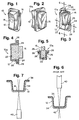
- FIG. 1 is a front perspective view of the button assembly of the invention illustrating the assembled formed cap and button support member;
- FIG. 2 is a rear perspective view of the button assembly of FIG. 1;
- FIG. 3 is a front perspective view of the button assembly of the invention, similar to FIG. 1, with a portion of the cap broken away;
- FIG. 4 is a longitudinal cross-sectional view of the button assembly taken along lines 4-4 of FIG. 3 and in the direction indicated generally;
- FIG. 5 is a lateral cross-sectional view of the button assembly taken along lines 5-5 of FIG. 3 and in the direction indicated generally;
- FIG. 6 is a lateral cross-sectional view of a cap illustrating prior art laser etching techniques which proved unsuccessful in the present invention;
- FIG. 7 is a lateral cross-sectional view of a cap of the present invention illustrating successful laser ablating as taught by the present invention;
- FIG. 8 is a perspective view of a formed cap of the present invention utilized to form a button having a complex three-dimensional shape and an intricate undistorted graphic therewith;
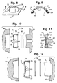
- FIG. 9 is a cross-sectional view of the complex formed cap taken along line 9-9 of FIG. 8 and in the direction indicated generally;
- FIG. 10 is an exploded cross-sectional view of a formed cap of the invention being inserted within a mould with desired colour foil layers;
- FIG. 11 is a longitudinal cross-sectional view of a button assembly formed by moulding as illustrated in FIG.10;
- FIG. 12 is an exploded cross-sectional view, similar to FIG. 10, illustrating another type of moulding utilized to provide the button assembly of FIGS 1-5;
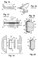
- FIG. 13 is a schematic diagram illustrating one method of forming the button assembly of the invention;
- FIG. 14 is a schematic diagram illustrating another method of forming the button assembly of the invention;
- FIG. 15 is a perspective exploded view of a two colour foil member of the invention;
- FIG. 16 is a sectional view of a portion of a dashboard and windshield of an automobile illustrating a light control film of the prior art applied over a light source;
- FIG. 17 is a side view of a prior art light control film;
- FIG. 18 is a longitudinal cross-sectional view of the prior art light control film of FIG. 17 applied across the front flat surface of a prior art back-lit button;
- FIG. 19 is an exploded cross-sectional view of a formed cap, light control film and colour film of the invention being inserted within a mould; and
- FIG. 20 is a longitudinal cross-sectional view of the moulded cap and light control film of the invention without the colour film.
- Referring to FIG. 1, the button assembly of the invention is designated generally by the
reference numeral 10. Theassembly 10 substantially includes two pieces, anopaque cap 12 having a desired translucent graphic image or "window" 14 formed therewith as described below and a clear or tinted transparent button support member or "light pipe" 16 which is secured within the interior of thecap 12. - Although the
assembly 10 is illustrated as a button, it is to be understood that the teachings of the present invention can be utilized to provide any type of display panel, insert or the like and without thesupport member 16. Additionally, thesupport member 16 can be any desired colour, including translucent white which then can be back-lit by a tinted bulb to provide the desired day time and night time characteristics described herein. - Two basic forms of the
assembly 10 are illustrated, both of which provide a one-piece structure whose shape and assembly can vary. The first form of theassembly 10a is illustrated in FIGS. 1 to 5 and 12 where thebutton support member 16 is formed before assembly and is slightly smaller than the desired final shape of thecap 12. - As FIG. 12 illustrates, the
cap 12 andbutton support member 16 are inserted within respective female andmale mould portions button support member 16 is secured to an interior 22 of thecap 12 by injection moulding aresin 24 in predetermined locations between thecap 12 and thebutton support member 16. To provide support toexterior edges 26 of thecap 12, theresin 24 can extend about theedges 26 to formshoulders 28, if desired. - The second form of the
assembly 10b is illustrated in FIGS. 10 and 11. For clarity, the invention will be described hereinafter with particular reference to assembly lob. It is to be understood, however, that the following description similarly applies toassembly 10a. - The
assembly 10b includes thecap 12 having the desired graphic 14 therewith which is inserted within afemale mould portion 18. The interior 22 then is filled withresin 24 during injection moulding to provide thesupport member 16 and the desired final shape of theassembly 10b illustrated in FIG. 11. - Typically, in use, the
assembly 10b is mounted on an external surface of an automobile control panel (not illustrated). Upon being depressed by a user, an outwardly extendingleg portion 29 of thesupport member 16 contacts a switch to provide a desired function. - As FIGS. 10 and 11 illustrate, the
cap 12 has a substantially rectangular configuration with a concavefront surface 30. Alternatively, as FIGS. 8 and 9 illustrate, thecap 12 can have a complex three dimensionalfront surface 32 of any desired shape. The present invention provides for such a variety of shapes of thecap 12 without any distortion of the graphic 14 and is usable in mass production to producemultiple caps 12 without compromising the quality of the graphic 14. - As FIGS. 9 to 11 illustrate, the
cap 12 includes atransparent member 34 approximately 15 mils (0.4 mm) thick with an opaque layer ofsuitable coating 36. Thetransparent member 34 includes a firstexterior side 38 which will be contacted by a user and a second interior or "second side" 39, including thecoating 36 thereon, which forms theinterior surface 22 of thecap 12. Preferably, thecoating 36 is a black ink between 1.5 to 2.0 mils 0.04 to 0.05 mm) thick having the thermal and mechanical properties necessary to withstand thermo-forming and moulding as described above in U.S. Patent No. 5,098,633 without any pin holes or other distortions. - The
coating 36 can be of any desired colour, including white, so long as the desired contrasting graphic 14 is provided. Additionally, thecap 12 andcoating 36 can be formed to provide a "dead front" type of graphic 14 which substantially only is visible when back-lit. - As FIG. 7 illustrates, the graphic 14, which can be of any desired shape or configuration, is removed or "ablated" from the
transparent member 34 by alaser 40 after first passing through thetransparent member 34. Details of thelaser 40 are provided below. - It is important to note that initially, as FIG. 6 illustrates, the graphic 14 was attempted to be formed by etching the
black layer 36 from thetransparent member 34 with alaser 40 directly in contact with theblack layer 36 as is known in the art of laser etching. This proved completely unsuccessful since, rather than etching away a desired graphic on theblack layer 36, thelaser 40 simply droveportions 42 of theblack layer 36 directly into thetransparent member 34. - It also is to be noted that the decision to reverse the
cap 12 and direct thelaser 40 first against thetransparent member 34 as illustrated in FIG. 7 was merely a matter of trial and error decided upon after the failed attempt to etch as described with regard to FIG. 6. Although theblack layer 36 removed according to FIG. 7 is described as being ablated, no residue or smoke was observed. - Preferably, the
laser 40 is a low heat, low power laser known as an "Excimer" laser which is tunable to different frequencies and utilizes ultra-violet light as opposed to a more commonly known high heat, high power infrared laser which tends to cause discolouration, burning, frosting and/or distortion. Theexcimer laser 40 uses a beam which is focused through a mask or stencil, illustrated in FIGS. 13 and 14, having any desired graphic 14. Once the beam passes through the desired portion of the mask, it contacts thecap 12 and ablates the desired portion of theblack layer 36 corresponding to the mask graphic without causing any damage or discolouration of thetransparent member 34. - The beam of the
excimer laser 40 can be rather wide and typically pulses while it sweeps across the surface of thecap 12. To provide the complex four letter graphic 14 of FIG. 8, approximately 20 pulses were utilized, but can vary. - It is to be noted that most laser etching techniques typically trace the pattern of the desired graphic with a narrow point beam, rather than a broader beam which pulses and sweeps as does the
excimer laser 40, which adds to the time needed to form the desired image and contributes to heat developed in the etched member. Thus, use of the beam and pulsing of theexcimer laser 40 decreases the time needed to form theimage 14 and heat build-up within thecap 12. - Use of the
excimer laser 40 thereby enables thetransparent member 34 to be formed into the desired shape after theblack layer 36 is applied but before any imaging or further processing. This eliminates any distortion associated with thermo-forming the graphic 14 as well as any thinning of theblack layer 36 or other colour layers described below. Furthermore, thelaser 40 provides the graphic 14 to exact dimensions and in a precise location on thecap 12 and is completely identically reproducible from part-to-part. This significantly increases the quality of theassembly 10 which in turn reduces costs associated with inspection and rejection ofassemblies 10. - As FIGS. 9 to 11 illustrate, after ablating the
cap 12 with thelaser 14, the graphic 14 is formed on thesecond side 39 of thetransparent member 34. The graphic 14 substantially is formed bytransparent portions 44 which were ablated and form the desired four letter graphic of FIG. 8. Thus, the graphic 14 is provided on the interior 22 of thecap 12 on thesecond side 39 which is known as a "second surface graphic". Consequently, before the graphic 14 can be eroded from contact by a user or other article, thetransparent member 34, which preferably is 15 mils (0.4 mm) thick, must first be worn through which would be rare during normal use throughout the life of theassembly 10b. - As FIG. 10 illustrates, in order to provide colour to the graphic 14, at least a first "day time"
translucent colour layer 46 is applied across thetransparent portion 44 on the interior 22 of thecap 12. Preferably, thefirst colour layer 46 is selected to provide contrast to the black orother colour layer 36 which forms the major colour of thecap 12 and is visible during daylight or when a light is directed across thecap 12. Typical colours for thefirst colour layer 46 include, but are not limited to, white and light grey as well as metallic colours such as gold, silver and the like. - Additionally, at least one second night time
translucent colour layer 48 is applied over thefirst colour layer 46 and thetransparent portion 44 on the interior 22 of thecap 12. Preferably, the second nighttime colour layer 48 is blue, green, red or orange and does not change the colour of thefirst layer 46 until thecap 12 is back-lit, thereby providing the night time colour through thefirst colour 46. - The second night time colour also can be provided by a tinted
translucent support member 16 or other insert which, when back-lit with a light source, conveys its colour through thefirst colour layer 46 to provide the night time colour. It also is possible to provide the second night time colour by using aclear support member 16 and a tinted bulb which conveys its colour through thesupport member 16 and thefirst colour layer 46 when illuminated. Alternatively, the first day time colour can be provided by a whitetranslucent support member 16 or other insert which can be back-lit by a tinted bulb to provide the second night time colour. - The
first colour layer 46 can be stamped with a pad, sprayed or silk-screened across thetransparent portion 44, either as a complete single layer or in a precise pattern, and allowed to dry. Thereafter, thesecond colour layer 48 similarly can be stamped with a pad, sprayed or silk-screened over thefirst layer 46 in a similar manner. - The
first colour layer 46 must be uniform in colour and appearance, bright during daylight or when exposed to direct lighting from the firstexterior side 38 of thecap 12 and translucent to enable thesecond colour layer 48 to pass therethrough when back-lit. Thesecond colour layer 48 similarly must provide a bright, uniform colour through thefirst colour layer 46 when back-lit. Neithercolour layer 46 nor 48 should have pin-holes or other imperfections in day time or when back-lit. - Preferably, the first and second colour layers 46 and 48 are provided by what are known as "Transparent Second Surface Foils" (TSS foils), also known as transfer foils. TSS foils typically are utilized in hot stamp decorating or heat transfer decorating of desired objects, such as book bindings and the like. No drying is necessary when using TSS foils.
- The TSS foils are composed of a .5 mil (13 µm) thick mylar polyester member coated on one surface with the desired colour and include an adhesive and a release agent. The colour preferably is provided by an ink or an extremely thin metallic layer, but can vary. If a metallic layer is utilized, aluminium is preferred due to its low cost, but silver, gold, copper, titanium, chromium, nickel and stainless steel also can be utilized. It is to be understood, however, that the particular material and thickness of the colour layer can vary so long as it functions as described herein.
- The TSS foils are thermally stable to withstand the temperatures of moulding and/or thermo-forming and provide a bright yet translucent and uniform colour across the
transparent portion 44. The adhesive and release agent can be omitted when TSS foils are utilized in the present invention. Alternatively, if desired, the colour foil can be heat transferred to thetransparent portion 44 and the mylar layer removed. - As FIG. 10 illustrates, the colour layers 46 and 48 can be provided by separate foils within the mould and then moulded to the
cap 12 into the shape illustrated in FIG. 11. Alternatively, as FIG. 15 illustrates, to provide ease of assembly, onefoil 50 can be provided having amylar member 52 and the twocolour layers - It is to be noted that unlike prior art devices, in the present invention more than the two
colour layers colour 48. Thus, for example, the back-lit colour of the "scan" graphic 14 of FIG. 8 can be provided with a white day time colour while each letter in the word "scan" can be of a different night time colour. This is provided in the present invention by merely pad stamping, silk-screening or using a different colour TSS foil over a desired letter. Multiple colours cannot be provided in the prior art devices mainly because back lighting is provided by thetinted light pipe 16 which can only provide one night time colour. - FIG. 13 illustrates the preferred steps necessary to form the
cap 12 using the TSS foils for mass production. Thetransparent member 34 having theblack layer 36 can be supplied in aroll 54 and inserted directly into a thermo-former 56 which forms thetransparent member 34 andblack layer 36 into a desired shape of thecap 12. After leaving the thermo-former 56, thelaser 40, positioned on thefirst side 38 of thetransparent member 34 opposite theblack layer 36, is focused through alens 58 and amask 60 to ablate the desired graphic 14 onto eachcap 12 by removing portions of theblack layer 36, leavingtransparent portions 44 on thecap 12 which form the graphic 14. - Next, the
white foil 46 andcolour foil 48 are inserted into the interior 22 of thecap 12 to cover thetransparent portion 44. Alternatively, asingle foil 52, illustrated in FIG. 15, can be inserted into the interior 22 of the cap 12 (not illustrated). Thecaps 12 then are conveyed into amoulding machine 62 having the male andfemale mould portions transparent resin 24 is injected into the interior 22 of thecaps 12 to form the desiredbutton assembly 10b. - FIG. 14 is similar to FIG. 13 up through the step of forming the graphic 14 with the
laser 40. Thereafter, thefirst colour layer 46 is silk-screened, pad printed or otherwise applied across thetransparent portion 44 on the interior 22 of thecap 12 and allowed to dry in afirst oven 64. Upon leaving thefirst oven 64, thesecond colour layer 48 is silk-screened, pad printed or otherwise applied across thefirst colour layer 46 and allowed to dry in asecond oven 66. After exiting thesecond oven 66, thecaps 12 are conveyed to amoulding machine 62 and thetransparent resin 24 is applied as described above. - It is to be noted that to form the
assembly 10a of FIGS. 1 to 5, the same process as described in either FIGS. 13 or 14 is applied up to the point of thecap 12 entering the male andfemale moulds moulding machine 62 and theresin 24 injected in pre-determined areas to provide thefinished assembly 10a. - In view of the above teachings, a number of variations of the
button assembly 10 are possible. For example, the steps of forming and ablating can be reversed. Thus, asheet 34 with ablack layer 36 can first be ablated by thelaser 40 to include the graphic 14. Thereafter, thesheet 34 and graphic 14 can be formed into acap 12, the colour layers 46 and 48 are inserted by one or more TSS foils or otherwise and thecap 12 is moulded as described above. - In this situation, however, since forming takes place after image ablating, the shape of the
cap 12 is limited to flat or slightly curvedfront surface 30 as illustrated in FIG. 10. Complex surfaces 32 as illustrated in FIG. 9 are possible, but the distortion of the image must be accounted for before forming which can be difficult to reproduce. It is conceivable, of course, that a completely automated, controlled system could accomplish forming complex shapes after ablating. - Similarly, after ablating a graphic 14 on a
flat sheet 34 the colour layers 46 and 48 can be hot stamped over thetransparent portions 44. Thesheet 34 thereafter would be formed and moulded as described above. - Finally, the
flat sheet 34 can have the.graphic 14 formed thereon by silk-screening, rather than laser ablating. Thereafter thesheet 34 would be formed into thecap 12 and one or more TSS foils applied to the interior 22 of thecap 12 and moulded. It is to be understood that the methods of providing thebutton assembly 10 are not limited to those described above. - FIGS. 16 to 18 illustrate a prior art light directing feature which sometimes is desirable for back-lit buttons. Briefly, a problem with illuminated dashboards and other control panels in automobiles is that light from these members contacts a
windshield 70 causing reflective glare to be directed into a driver's eyes and impairing vision. - In order to direct the light from a
light source 72 away from thewindshield 70, a commercially available prior art light control film (LCF) 74, such as that manufactured by the 3M Company, can be inserted in front of the light 72. As FIG. 17 illustrates, theLCF 74 is formed with acentral core 76 including a plurality of opaque layers orlouvres 78 interspersed with clear layers orsections 80. The core 76 then is sandwiched between two clearprotective films films core 76. - FIG. 18 illustrates an
LCF 74 utilized with a prior art back-litbutton 100 which is formed by the prior art "paint and laser method" described above. To provide thebutton 100, a translucent colour tinted button support member orlight pipe 102 of a pre-determined colour and configuration first is coated with a translucentday time colour 104, such as white, and allowed to dry. Thereafter, a blackopaque layer 106 is coated over top of thewhite layer 104, is allowed to dry, and a laser (not illustrated) is directed against theblack layer 106 to etch away a desiredpattern 108 to expose portions of thewhite layer 104 through theblack layer 106. TheLCF 74 then is secured over theblack layer 106, such as with an adhesive or other means. - In order to provide the desired light directing, however, the
button 100 must provide a substantiallyflat surface 110 over which thepattern 108 andLCF 74 are provided. Thus, theLCF 74 cannot be utilized with non-planar surfaces, such assurface 30 illustrated in FIGS. 10, 11, 19 and 20, let alone complex three-dimensional shapes as thecap 12 of the present invention illustrated in FIG. 8. Additionally, theclear film 82 shown on the outside surface of theLCF 74 is extremely thin and can be scratched by a foreign object, such as a key, fingernail, etc., thereby distorting the effects of theLCF 74 and exposing the core 76 to scratching or wear. - As FIGS. 19 and 20 illustrate, the
button assembly 10a of the present invention can be utilized with a core 90 that does not include any protective layers, such aslayers cap 12, the core 90 can be inserted directly within theinterior 22 of thecap 12 behind the ablatedblack layer 36 before moulding, similar to thefoils translucent resin 24, which can be either clear or tinted to a desired colour, can be injection moulded as described above to provide an integrally formed finishedbutton assembly 10a having light directing properties. Thus, thecore 90 is subjected to thermo-forming and moulding temperatures and pressures and does not distort. - It is to be noted that when the
core 90 is mounted within theinterior 22 of thecap 12, the core 90 like the graphic 14 is not exposed to a user and thus is not susceptible to scratches and wear as is theLCF 74 of theprior art button 100. Additionally, as FIG. 20 illustrates, the core 90 can be bent to accommodate curved or three dimensional surfaces of thecap 12 while still providing the desired light directing since the louvres 92 are slightly aligned with thecurved surface 30 of thecap 12. - Alternatively, the core 90 can be utilized with one or both of the
protective layers cap 12 as described above. Furthermore, thecore 90, with or without theprotective layers first surface 38 of the formedcap 12 and can be utilized with a flattransparent sheet 34 andcoating 36 and then thermo-formed into thecap 12 without detracting from the light control properties thereof. - In any event, the core 90 with or without the
protective layers second surface 39 orinterior 22 of a display or button and can withstand the temperatures and pressures of thermo-forming and/or moulding. - Day time and night time colours also can be utilized with the
core 90. Preferably, as FIG. 19 illustrates, the day time colour is provided with acolour TSS foil 93, similar to thefoils cap 12. The second night time colour then can be provided on the opposite side of the core 90 with another colour TSS foil, atinted support member 16 or aclear support member 16 illuminated with a tinted bulb. - In order to reduce scattering of the light by the day time colour TSS foil after the light is directed by the
core 90, the thickness of the day timecolour TSS foil 93 is selected to be very thin. Preferably, the thickness must be sufficient to provide the desired day time colour yet prevent scattering when back-lit. The preferred day time colours for the TSS foils 93 in front of the core 90 are metallic gold and silver due to the metallic appearance and ease of providing the desired thin layers with these colours. Other colours, including non-metallic colours, are possible, however, so long as they provide the desired day time colour without scattering. - Preferably, the gold and silver metallic colours are provided by an extremely thin metallized film. As described above, the metal utilized to provide the colour film can be either aluminum, silver, gold, copper, titanium, chromium, nickel or stainless steel, but can vary. Aluminum preferably is used due to its colour and low cost.
- The metal layer is provided on one side of a thin mylar polyester sheet by vapour deposition and is referred to as "vapour metallizing". When aluminum is utilized by itself, the daytime colour substantially is metallic silver which takes on a metallic gun metal blue appearance with extremely thin layers. To provide other substantially metallic colours, a thin layer of coloured varnish or the like, such as gold, first is provided on the mylar sheet with the aluminum deposited over it. When formed, the aluminum layer faces the core 90 with the coloured varnish facing the
cap 12 to provide the desired daytime colour. - The thickness of the metallized layer typically is expressed in terms of angstroms, optical density and percentage of light transmission. Thicknesses below 30 angstroms (3 nm) are more easily measured by optical density and percentage of light transmission. With aluminum, a thickness of approximately 30 angstroms (3 nm) has a corresponding optical density of approximately 1.00 and light transmission of approximately 10%.
- As the metallic layer becomes thinner, more light is transmitted through it. With thinner layers, however, the daytime colour provided by the metallic layer is less visible. Thus, a balance between daytime colour and light transmission must be achieved.
- In actual testing with aluminum, layers have been achieved with optical densities of at least .004 having light transmission between 80 to 100%. Extremely thin layers, however, are difficult to accurately apply and measure. Good results have been achieved with layers having optical densities between 0.80 and 1.77 with corresponding light transmission of approximately 16% and 2% respectively.
- These values, however, can be higher or lower so long as the desired daytime colour and light transmission are provided. Thus, the invention is not to be limited to a specific thickness, material or colour of the colour layer or metallized foil.
Claims (14)
- A button assembly (10) having a graphic image of a first colour and which, when back-lit, provides a graphic image of a different colour comprising:
a transparent formed cap member (30) having a predetermined shape, a first exterior surface (34) and a second interior surface (36), said second interior surface (36) being provided with opaque means (22) having a predetermined clear portion (44) forming a graphic image;
first translucent colour means (46) on said second side of said cap (12) at least covering said clear graphic image portion;
second translucent colour means (48) on said second side of said cap (12) at least covering said first colour means (46); and
transparent button support means (16) connected to said cap (30) for providing support to said cap (30) and for co-operation with said second side (36) of said cap (30) behind said first (46) and second (48) colour means so that when viewed from the first side of said cap (30), said button assembly (10) includes a graphic image having a colour corresponding to that of said first colour means (48) and when back-lit from said second side of said cap said graphic image has a different colour. - An assembly according to claim 1, wherein said clear portion of said opaque means (22) is ablated away using a laser beam directed through said transparent cap member (30).
- An assembly according to claim 1 or 2, wherein said first and second colour means are separate colour foil means (46, 48) or are contained on a single colour foil means.
- An assembly according to any one of the preceding claims, wherein said formed cap member (30) is of a complex three-dimensional shape.
- An assembly having a translucent image thereon which, when back-lit, directs the light transmitted through the image and emanating from a first side of the assembly in a pre-determined pattern, comprising:
a sheet member having a first front side and a second opposite rear side;
a translucent graphic image on said second side of said sheet member; and
light directing film means covering said graphic image for directing light emanating from said first side of said sheet member in a pre-determined pattern. - An assembly as defined in claim 5, wherein said sheet member is transparent and said translucent graphic image is a laser formed image provided by coating said second side of said sheet member with an opaque coating and removing desired portions of said coating with a laser or is a screen printed image formed on said second side of said sheet member.
- An assembly as defined in claim 5 or 6, wherein said film means are positioned on said first side of said sheet member or on said second side of said sheet member.
- An assembly as defined in any one of claims 5, 6 or 7, including a first daytime translucent colour means covering said translucent graphic image on said second side of said sheet member.
- An assembly as defined in claim 8, wherein said first daytime translucent colour means are gold or silver.
- An assembly as defined in claim 8, wherein said first daytime translucent colour means are a first foil member.
- An assembly as defined in claim 10, wherein said foil member is a metallic foil of sufficient thickness to provide the desired daytime colour yet prevent light scattering when back-lit.
- An assembly as defined in claim 8, 9, 10 or 11 including a second night time translucent colour means covering said first colour means, said second colour means being visible from the first side of said sheet member when back-lit.
- An assembly as defined in claim 12, wherein said second colour means are a second foil member or are a tinted support member connected to said second side of said sheet member or are a clear support member connected to said second side of said sheet member and a tinted bulb for back lighting said assembly.
- An assembly as defined in claim 7 or any claim dependent upon claim 7, including a first foil member positioned between said second side of said sheet member and said film means to provide a first daytime translucent colour to said graphic image and a second foil member positioned on the opposite side of said film means to provide a second night time colour to said graphic image.
Applications Claiming Priority (2)
| Application Number | Priority Date | Filing Date | Title |
|---|---|---|---|
| US52511 | 1993-04-29 | ||
| US08/052,511 US5376314A (en) | 1993-04-29 | 1993-04-29 | Method of making a laser ablated formed cap |
Publications (1)
| Publication Number | Publication Date |
|---|---|
| EP0622585A1 true EP0622585A1 (en) | 1994-11-02 |
Family
ID=21978091
Family Applications (1)
| Application Number | Title | Priority Date | Filing Date |
|---|---|---|---|
| EP94302920A Ceased EP0622585A1 (en) | 1993-04-29 | 1994-04-25 | Image carrying devices |
Country Status (2)
| Country | Link |
|---|---|
| US (2) | US5376314A (en) |
| EP (1) | EP0622585A1 (en) |
Cited By (13)
| Publication number | Priority date | Publication date | Assignee | Title |
|---|---|---|---|---|
| EP0772213A1 (en) * | 1995-11-01 | 1997-05-07 | Fuji Polymertech Co., Ltd | Manufacturing method for key tops |
| EP1217491A1 (en) * | 2000-12-21 | 2002-06-26 | Siemens Aktiengesellschaft | Backlit control button and method of fabrication |
| FR2831853A1 (en) * | 2001-11-07 | 2003-05-09 | Siemens Ag | PLASTIC INJECTED PART WITH OPTICAL DISPLAY FUNCTION AND METHOD FOR MANUFACTURING THIS INJECTED PART |
| WO2003071565A1 (en) * | 2002-02-19 | 2003-08-28 | Bo Mineur | Illuminated control |
| EP1132932A3 (en) * | 2000-03-06 | 2004-01-14 | Polymatech Co., Ltd. | Key Sheet |
| WO2007124900A1 (en) | 2006-04-28 | 2007-11-08 | Preh Gmbh | Operating element for a motor vehicle |
| EP1965401A1 (en) * | 2007-02-28 | 2008-09-03 | Research In Motion Limited | Backlighted key for a keypad of an electronic device |
| US7582839B2 (en) | 2007-02-28 | 2009-09-01 | Research In Motion Limited | Backlighted key for a keypad of an electronic device |
| DE102008062579B3 (en) * | 2008-12-16 | 2009-12-10 | Preh Gmbh | Operating element cap for use in e.g. instrument panel of motor vehicle, has refractive microspheres embedded in opaque matrix, and transparent carrier plate arranged between foil and mask |
| DE102008062577B3 (en) * | 2008-12-16 | 2009-12-10 | Preh Gmbh | Cap for use in e.g. operating element in motor vehicle, has light sources producing light beams directed in parallel, lenticular screen film arranged between film and sources, and mask formed as strip pattern between films |
| US20130063050A1 (en) * | 2011-09-13 | 2013-03-14 | Panasonic Corporation | Electronic device, light emitting unit, and light-transmissive panel |
| DE102016108614A1 (en) * | 2016-05-10 | 2017-11-16 | Dr. Schneider Kunststoffwerke Gmbh | Method for producing an at least partially transilluminable component and component |
| DE102018127894A1 (en) * | 2018-03-09 | 2019-09-12 | Seoyon America Corp. | A soft top cowl for a vehicle door switch assembly and method of making same |
Families Citing this family (53)
| Publication number | Priority date | Publication date | Assignee | Title |
|---|---|---|---|---|
| US6048588A (en) * | 1988-07-08 | 2000-04-11 | Cauldron Limited Partnership | Method for enhancing chemisorption of material |
| EP0734325B1 (en) * | 1993-12-17 | 1997-12-29 | Minnesota Mining And Manufacturing Company | Ablative imaging by proximity lithography |
| US5614338A (en) * | 1995-04-14 | 1997-03-25 | Delco Electronics Corporation | Process for manufacturing backlit displays utilizing treated plastics and laser energy |
| US5958628A (en) * | 1995-06-06 | 1999-09-28 | International Business Machines Corporation | Formation of punch inspection masks and other devices using a laser |
| US6469728B1 (en) * | 1995-12-18 | 2002-10-22 | Xerox Corporation | LED printbars with depth of focus enhancement |
| US5845365A (en) * | 1996-01-05 | 1998-12-08 | The Grigoleit Company | Method for manufacturing an indicator knob and a knob |
| US5811175A (en) * | 1996-01-05 | 1998-09-22 | The Grigoleit Company | Method of manufacturing a composite article having a high clarity icon and the product produced by the method |
| US5681515A (en) * | 1996-04-12 | 1997-10-28 | Motorola, Inc. | Method of fabricating an elastomeric keypad |
| US6752946B2 (en) * | 1996-09-27 | 2004-06-22 | Nissha Printing Co., Ltd. | Cellular phone top cover and method of manufacturing the cellular phone top cover |
| US6677545B2 (en) * | 1997-02-18 | 2004-01-13 | Sunarrow Co., Ltd. | Illumination key and method of manufacture |
| AUPO523997A0 (en) * | 1997-02-20 | 1997-04-11 | Securency Pty Ltd | Laser marking of articles |
| DE19758496A1 (en) * | 1997-04-25 | 1999-03-25 | Trw Automotive Electron & Comp | Transparent illuminated aperture part or actuator part manufacturing method |
| US6207330B1 (en) | 1997-07-14 | 2001-03-27 | International Business Machines Corporation | Formation of punch inspection masks and other devices using a laser |
| US6326569B1 (en) | 1998-03-31 | 2001-12-04 | Key Plastics, Inc. | Control panel assembly and method of making same |
| DE19953046A1 (en) * | 1998-11-09 | 2000-05-11 | Marquardt Gmbh | Electric switch for use under rough operating conditions comprises a bellows-like sleeve whose ends are connected respectively to the top section of the switch cap and to a housing section below the switch cap |
| US6277312B1 (en) | 1999-03-11 | 2001-08-21 | Serigraph, Inc. | In-mold decorating with laser etching |
| US6284184B1 (en) | 1999-08-27 | 2001-09-04 | Avaya Technology Corp | Method of laser marking one or more colors on plastic substrates |
| US6591457B1 (en) * | 2000-06-08 | 2003-07-15 | The Grigoleit Company | Multi-component button and a method of manufacturing it |
| US6499191B1 (en) | 2000-06-29 | 2002-12-31 | The Grigoleit Company | Knob with a composite light pipe having a colored face and a light pipe |
| US7211214B2 (en) * | 2000-07-18 | 2007-05-01 | Princeton University | Laser assisted direct imprint lithography |
| US8269793B2 (en) * | 2003-02-18 | 2012-09-18 | Serverside Group Limited | Apparatus and method for manipulating images |
| AU2003901532A0 (en) * | 2003-04-04 | 2003-05-01 | Evolution Broadcast Pty Limited | Broadcast control |
| DE10339842B4 (en) * | 2003-08-29 | 2008-02-14 | Angell-Demmel Europe Gmbh | Method of making buttons, ornamental and instrument panels with fine symbolism and a button made by the method |
| DE10342142A1 (en) * | 2003-09-12 | 2005-04-14 | Preh Gmbh | Control element with freely programmable symbols |
| US7143495B2 (en) * | 2004-03-05 | 2006-12-05 | Wing Brandon M | Backlight etching process |
| US7036188B1 (en) | 2004-03-24 | 2006-05-02 | The Grigoleit Company | Composite knob with light pipe leakage barrier |
| US20060071901A1 (en) * | 2004-10-05 | 2006-04-06 | Feldman Mark G | Graphic illumination for contact-less control |
| EP1712323A1 (en) * | 2005-04-15 | 2006-10-18 | Inmotech Technology Corporation | Method for making a three dimensional laser tag on a transparent membrane before an in-mould injection step |
| AU2006259705B2 (en) * | 2005-06-16 | 2012-05-17 | Avery Dennison Corporation | Retroreflective sheet structure |
| US20090133448A1 (en) * | 2005-12-23 | 2009-05-28 | Ju Han Yoon | Laundry device |
| JP2007294320A (en) * | 2006-04-26 | 2007-11-08 | Sunarrow Ltd | Method for manufacturing key top for pushbutton switch |
| WO2008026844A2 (en) * | 2006-08-31 | 2008-03-06 | Lg Electronics Inc. | Control panel assembly for laundry device and laundry device including the same |
| KR20080021920A (en) * | 2006-09-05 | 2008-03-10 | 삼성전자주식회사 | Transparent ink printing method and transparent ink |
| DE102007029314A1 (en) * | 2006-09-22 | 2008-04-03 | Preh Gmbh | Cap for displays or control switches comprises cover which fits over light source or switch and is designed so that illuminated symbol is displayed on its upper surface, underside of cover carrying translucent metal layer, applied by PVD |
| EP1927455A1 (en) * | 2006-11-28 | 2008-06-04 | Koninklijke Philips Electronics N.V. | Method for manufacturing a housing element having a decorative covering and a grip layer, a decorated foil and the housing element |
| US7578955B2 (en) * | 2007-07-30 | 2009-08-25 | Motorola, Inc. | In-mold separated light guides |
| JP5326734B2 (en) * | 2009-03-27 | 2013-10-30 | 住友電装株式会社 | Manufacturing method of display member and molded article for display member |
| TW201104718A (en) * | 2009-07-23 | 2011-02-01 | Ichia Tech Inc | Method of fabricating keycaps |
| JP5282694B2 (en) * | 2009-07-28 | 2013-09-04 | 住友電装株式会社 | Manufacturing method of design panel and design panel obtained by the manufacturing method |
| US8248265B2 (en) * | 2009-09-17 | 2012-08-21 | Toyota Motor Engineering & Manufacturing North America, Inc. | Vehicle console display buttons and vehicle consoles incorporating the same |
| TWI431567B (en) * | 2010-08-18 | 2014-03-21 | Au Optronics Corp | Curve-shaped display module, manufacture method thereof, and manufacture apparatus for manufacturing the same |
| TR201807292T4 (en) * | 2010-12-28 | 2018-06-21 | Koninklijke Philips Nv | Hidden user interface for personal care devices and the way to do this. |
| US8593727B2 (en) | 2011-04-25 | 2013-11-26 | Vladimir G. Kozlov | Single-shot laser ablation of a metal film on a polymer membrane |
| TW201338958A (en) * | 2012-03-21 | 2013-10-01 | Darfon Electronics Corp | Keycap and method of manufacturing the same |
| US20130334194A1 (en) * | 2012-06-15 | 2013-12-19 | Chien-Chou Chen | Temperature control device seamed on clothes |
| US9318149B2 (en) | 2013-03-01 | 2016-04-19 | Gvbb Holdings S.A.R.L. | Method and system of composite broadcast control |
| FR3007104B1 (en) | 2013-06-13 | 2019-01-25 | IFP Energies Nouvelles | METHOD AND INSTALLATION OF COMBUSTION BY OXYDO-CHEMICAL LOOP REDUCTION OF A SOLID HYDROCARBONIC LOAD |
| DE102013014420A1 (en) * | 2013-08-29 | 2015-03-05 | Leopold Kostal Gmbh & Co. Kg | Process for the production of a decorative part and decorative part produced by this process |
| TWI618625B (en) * | 2014-10-03 | 2018-03-21 | 綠點高新科技股份有限公司 | Method for making molded article with fiber composite material and article thereof |
| US10559237B2 (en) * | 2015-07-24 | 2020-02-11 | The Boeing Company | Method for conforming a display panel |
| US10743972B2 (en) * | 2016-01-26 | 2020-08-18 | Koninklijke Philips N.V. | Hidden user interface panel for personal care appliances and method of making same |
| TWI651745B (en) * | 2017-11-23 | 2019-02-21 | 世洋科技股份有限公司 | Method for manufacturing a key cap for a cover type keyboard device |
| US11143372B1 (en) * | 2021-06-10 | 2021-10-12 | Steve Wriggle | Safety device cabinet with a safety switch having an integrated light |
Citations (5)
| Publication number | Priority date | Publication date | Assignee | Title |
|---|---|---|---|---|
| US3139616A (en) * | 1960-11-01 | 1964-06-30 | Don M Hallerberg | Changeable color illuminated indicating device |
| EP0245853A2 (en) * | 1986-05-14 | 1987-11-19 | Marui Industry Co. Ltd. | Light-transmitting material for illuminated indicator |
| US4811179A (en) * | 1986-04-28 | 1989-03-07 | Koito Manufacturing Co., Ltd. | Display device |
| US4855877A (en) * | 1987-12-01 | 1989-08-08 | Koito Seisakusho Co., Ltd. | Combination lamp assembly of monochromatic appearance capable of glowing in different colors |
| EP0448249A2 (en) * | 1990-03-19 | 1991-09-25 | Illinois Tool Works Inc. | Method and die for forming a shaped component |
Family Cites Families (8)
| Publication number | Priority date | Publication date | Assignee | Title |
|---|---|---|---|---|
| US3919559A (en) * | 1972-08-28 | 1975-11-11 | Minnesota Mining & Mfg | Louvered film for unidirectional light from a point source |
| US3922440A (en) * | 1974-08-16 | 1975-11-25 | Minnesota Mining & Mfg | Safety glass light control medium |
| CA1319341C (en) * | 1985-03-29 | 1993-06-22 | Frederick J. Fox | Method of supporting a louvered plastic film |
| US4766023A (en) * | 1987-01-16 | 1988-08-23 | Minnesota Mining And Manufacturing Company | Method for making a flexible louvered plastic film with protective coatings and film produced thereby |
| US4851061A (en) * | 1987-03-16 | 1989-07-25 | Sorkoram Paul O | Method and apparatus for patterned cut of thermoplastics |
| US5005949A (en) * | 1988-10-27 | 1991-04-09 | Shin Etsu Polymer Co., Ltd. | Anti-glare covering for illuminate indicator |
| US5142415A (en) * | 1989-06-15 | 1992-08-25 | Minnesota Mining And Manufacturing Company | Back-lit display |
| US5147716A (en) * | 1989-06-16 | 1992-09-15 | Minnesota Mining And Manufacturing Company | Multi-directional light control film |
-
1993
- 1993-04-29 US US08/052,511 patent/US5376314A/en not_active Expired - Lifetime
-
1994
- 1994-04-25 EP EP94302920A patent/EP0622585A1/en not_active Ceased
- 1994-07-29 US US08/282,446 patent/US5477024A/en not_active Expired - Lifetime
Patent Citations (5)
| Publication number | Priority date | Publication date | Assignee | Title |
|---|---|---|---|---|
| US3139616A (en) * | 1960-11-01 | 1964-06-30 | Don M Hallerberg | Changeable color illuminated indicating device |
| US4811179A (en) * | 1986-04-28 | 1989-03-07 | Koito Manufacturing Co., Ltd. | Display device |
| EP0245853A2 (en) * | 1986-05-14 | 1987-11-19 | Marui Industry Co. Ltd. | Light-transmitting material for illuminated indicator |
| US4855877A (en) * | 1987-12-01 | 1989-08-08 | Koito Seisakusho Co., Ltd. | Combination lamp assembly of monochromatic appearance capable of glowing in different colors |
| EP0448249A2 (en) * | 1990-03-19 | 1991-09-25 | Illinois Tool Works Inc. | Method and die for forming a shaped component |
Cited By (20)
| Publication number | Priority date | Publication date | Assignee | Title |
|---|---|---|---|---|
| EP0772213A1 (en) * | 1995-11-01 | 1997-05-07 | Fuji Polymertech Co., Ltd | Manufacturing method for key tops |
| EP1132932A3 (en) * | 2000-03-06 | 2004-01-14 | Polymatech Co., Ltd. | Key Sheet |
| EP1217491A1 (en) * | 2000-12-21 | 2002-06-26 | Siemens Aktiengesellschaft | Backlit control button and method of fabrication |
| FR2831853A1 (en) * | 2001-11-07 | 2003-05-09 | Siemens Ag | PLASTIC INJECTED PART WITH OPTICAL DISPLAY FUNCTION AND METHOD FOR MANUFACTURING THIS INJECTED PART |
| WO2003071565A1 (en) * | 2002-02-19 | 2003-08-28 | Bo Mineur | Illuminated control |
| WO2007124900A1 (en) | 2006-04-28 | 2007-11-08 | Preh Gmbh | Operating element for a motor vehicle |
| DE102007018905B4 (en) * | 2006-04-28 | 2012-10-31 | Preh Gmbh | Operating element for a motor vehicle |
| US7977593B2 (en) | 2007-02-28 | 2011-07-12 | Research In Motion Limited | Backlighted key for a keypad of an electronic device |
| EP1965401A1 (en) * | 2007-02-28 | 2008-09-03 | Research In Motion Limited | Backlighted key for a keypad of an electronic device |
| EP2065910A1 (en) | 2007-02-28 | 2009-06-03 | Research In Motion Limited | Backlighted key assembly for a keypad of an electronic device |
| US7582839B2 (en) | 2007-02-28 | 2009-09-01 | Research In Motion Limited | Backlighted key for a keypad of an electronic device |
| DE102008062577B3 (en) * | 2008-12-16 | 2009-12-10 | Preh Gmbh | Cap for use in e.g. operating element in motor vehicle, has light sources producing light beams directed in parallel, lenticular screen film arranged between film and sources, and mask formed as strip pattern between films |
| DE102008062579B3 (en) * | 2008-12-16 | 2009-12-10 | Preh Gmbh | Operating element cap for use in e.g. instrument panel of motor vehicle, has refractive microspheres embedded in opaque matrix, and transparent carrier plate arranged between foil and mask |
| US20130063050A1 (en) * | 2011-09-13 | 2013-03-14 | Panasonic Corporation | Electronic device, light emitting unit, and light-transmissive panel |
| DE102016108614A1 (en) * | 2016-05-10 | 2017-11-16 | Dr. Schneider Kunststoffwerke Gmbh | Method for producing an at least partially transilluminable component and component |
| DE102016108614B4 (en) * | 2016-05-10 | 2018-02-22 | Dr. Schneider Kunststoffwerke Gmbh | Method for producing an at least partially transilluminable component and component |
| DE102018127894A1 (en) * | 2018-03-09 | 2019-09-12 | Seoyon America Corp. | A soft top cowl for a vehicle door switch assembly and method of making same |
| US10688922B2 (en) | 2018-03-09 | 2020-06-23 | Seoyon E-Hwa Co., Ltd. | Soft upper trim for switch assembly of vehicle door and method of manufacturing the same |
| US10967783B2 (en) | 2018-03-09 | 2021-04-06 | Seoyon E-Hwa Co., Ltd. | Soft upper trim for switch assembly of vehicle door and method of manufacturing the same |
| DE102018127894B4 (en) | 2018-03-09 | 2025-01-02 | Seoyon America Corp. | Soft upper panel for a switch assembly of a vehicle door and method of manufacturing the same |
Also Published As
| Publication number | Publication date |
|---|---|
| US5376314A (en) | 1994-12-27 |
| US5477024A (en) | 1995-12-19 |
Similar Documents
| Publication | Publication Date | Title |
|---|---|---|
| US5376314A (en) | Method of making a laser ablated formed cap | |
| US5432684A (en) | Process for manufacturing painted backlit displays having uniform backlighting intensity | |
| US5009020A (en) | Light-passing decorative object | |
| EP1188534B1 (en) | Method for producing a decorated injection moulded product | |
| US6277312B1 (en) | In-mold decorating with laser etching | |
| US6663252B1 (en) | Automotive display panel | |
| EP1808880A1 (en) | Key sheet and key top with half-silvered mirror decoration | |
| US12337769B2 (en) | Control unit for a vehicle interior and method for producing the control unit | |
| US5120920A (en) | Key top | |
| WO2000067049A2 (en) | Mirror display | |
| KR20010020264A (en) | Method for producing an aperture part, an actuating part or similar parts with function symbols, for illumination by transmitted light | |
| EP1132932B1 (en) | Key Sheet | |
| US4663869A (en) | Display for displaying images in three dimensions | |
| CN112706469A (en) | Vehicle trim panel and method of forming the same | |
| US5130825A (en) | Arrangement for graphic representation using holographic foils | |
| JPH071991A (en) | Plastic article for decoration and its preparation | |
| JP2001030290A (en) | Molding decorated with laser marking and manufacture thereof | |
| EP3620755B1 (en) | Dial plate | |
| KR20050042011A (en) | Automotive lamp | |
| JPH0763987B2 (en) | Meter panel and manufacturing method thereof | |
| JP2000305495A (en) | Colored translucent display and its production | |
| JPH10267700A (en) | Instrument front panel and method of manufacturing the same | |
| JPH06143529A (en) | Decorative display and manufacture thereof | |
| JPH0784533A (en) | Display panel | |
| JPH04307288A (en) | Preparation of operation display panel |
Legal Events
| Date | Code | Title | Description |
|---|---|---|---|
| PUAI | Public reference made under article 153(3) epc to a published international application that has entered the european phase |
Free format text: ORIGINAL CODE: 0009012 |
|
| AK | Designated contracting states |
Kind code of ref document: A1 Designated state(s): DE ES FR GB IT |
|
| 17P | Request for examination filed |
Effective date: 19950412 |
|
| 17Q | First examination report despatched |
Effective date: 19951205 |
|
| GRAG | Despatch of communication of intention to grant |
Free format text: ORIGINAL CODE: EPIDOS AGRA |
|
| STAA | Information on the status of an ep patent application or granted ep patent |
Free format text: STATUS: THE APPLICATION HAS BEEN REFUSED |
|
| 18R | Application refused |
Effective date: 19970908 |