EP0622531A1 - Pipe assembly for efficient light-off of catalytic converter - Google Patents
Pipe assembly for efficient light-off of catalytic converter Download PDFInfo
- Publication number
- EP0622531A1 EP0622531A1 EP93114492A EP93114492A EP0622531A1 EP 0622531 A1 EP0622531 A1 EP 0622531A1 EP 93114492 A EP93114492 A EP 93114492A EP 93114492 A EP93114492 A EP 93114492A EP 0622531 A1 EP0622531 A1 EP 0622531A1
- Authority
- EP
- European Patent Office
- Prior art keywords
- pipe
- corrugations
- assembly
- inner pipe
- bend
- Prior art date
- Legal status (The legal status is an assumption and is not a legal conclusion. Google has not performed a legal analysis and makes no representation as to the accuracy of the status listed.)
- Granted
Links
Images

Classifications
-
- F—MECHANICAL ENGINEERING; LIGHTING; HEATING; WEAPONS; BLASTING
- F01—MACHINES OR ENGINES IN GENERAL; ENGINE PLANTS IN GENERAL; STEAM ENGINES
- F01N—GAS-FLOW SILENCERS OR EXHAUST APPARATUS FOR MACHINES OR ENGINES IN GENERAL; GAS-FLOW SILENCERS OR EXHAUST APPARATUS FOR INTERNAL COMBUSTION ENGINES
- F01N13/00—Exhaust or silencing apparatus characterised by constructional features ; Exhaust or silencing apparatus, or parts thereof, having pertinent characteristics not provided for in, or of interest apart from, groups F01N1/00 - F01N5/00, F01N9/00, F01N11/00
- F01N13/08—Other arrangements or adaptations of exhaust conduits
-
- F—MECHANICAL ENGINEERING; LIGHTING; HEATING; WEAPONS; BLASTING
- F01—MACHINES OR ENGINES IN GENERAL; ENGINE PLANTS IN GENERAL; STEAM ENGINES
- F01N—GAS-FLOW SILENCERS OR EXHAUST APPARATUS FOR MACHINES OR ENGINES IN GENERAL; GAS-FLOW SILENCERS OR EXHAUST APPARATUS FOR INTERNAL COMBUSTION ENGINES
- F01N13/00—Exhaust or silencing apparatus characterised by constructional features ; Exhaust or silencing apparatus, or parts thereof, having pertinent characteristics not provided for in, or of interest apart from, groups F01N1/00 - F01N5/00, F01N9/00, F01N11/00
- F01N13/14—Exhaust or silencing apparatus characterised by constructional features ; Exhaust or silencing apparatus, or parts thereof, having pertinent characteristics not provided for in, or of interest apart from, groups F01N1/00 - F01N5/00, F01N9/00, F01N11/00 having thermal insulation
- F01N13/141—Double-walled exhaust pipes or housings
-
- F—MECHANICAL ENGINEERING; LIGHTING; HEATING; WEAPONS; BLASTING
- F01—MACHINES OR ENGINES IN GENERAL; ENGINE PLANTS IN GENERAL; STEAM ENGINES
- F01N—GAS-FLOW SILENCERS OR EXHAUST APPARATUS FOR MACHINES OR ENGINES IN GENERAL; GAS-FLOW SILENCERS OR EXHAUST APPARATUS FOR INTERNAL COMBUSTION ENGINES
- F01N13/00—Exhaust or silencing apparatus characterised by constructional features ; Exhaust or silencing apparatus, or parts thereof, having pertinent characteristics not provided for in, or of interest apart from, groups F01N1/00 - F01N5/00, F01N9/00, F01N11/00
- F01N13/18—Construction facilitating manufacture, assembly, or disassembly
- F01N13/1838—Construction facilitating manufacture, assembly, or disassembly characterised by the type of connection between parts of exhaust or silencing apparatus, e.g. between housing and tubes, between tubes and baffles
- F01N13/1844—Mechanical joints
- F01N13/185—Mechanical joints the connection being realised by deforming housing, tube, baffle, plate, or parts thereof
-
- F—MECHANICAL ENGINEERING; LIGHTING; HEATING; WEAPONS; BLASTING
- F16—ENGINEERING ELEMENTS AND UNITS; GENERAL MEASURES FOR PRODUCING AND MAINTAINING EFFECTIVE FUNCTIONING OF MACHINES OR INSTALLATIONS; THERMAL INSULATION IN GENERAL
- F16L—PIPES; JOINTS OR FITTINGS FOR PIPES; SUPPORTS FOR PIPES, CABLES OR PROTECTIVE TUBING; MEANS FOR THERMAL INSULATION IN GENERAL
- F16L59/00—Thermal insulation in general
- F16L59/06—Arrangements using an air layer or vacuum
-
- F—MECHANICAL ENGINEERING; LIGHTING; HEATING; WEAPONS; BLASTING
- F01—MACHINES OR ENGINES IN GENERAL; ENGINE PLANTS IN GENERAL; STEAM ENGINES
- F01N—GAS-FLOW SILENCERS OR EXHAUST APPARATUS FOR MACHINES OR ENGINES IN GENERAL; GAS-FLOW SILENCERS OR EXHAUST APPARATUS FOR INTERNAL COMBUSTION ENGINES
- F01N2450/00—Methods or apparatus for fitting, inserting or repairing different elements
- F01N2450/20—Methods or apparatus for fitting, inserting or repairing different elements by mechanical joints, e.g. by deforming housing, tube, baffle plate or parts thereof
-
- F—MECHANICAL ENGINEERING; LIGHTING; HEATING; WEAPONS; BLASTING
- F01—MACHINES OR ENGINES IN GENERAL; ENGINE PLANTS IN GENERAL; STEAM ENGINES
- F01N—GAS-FLOW SILENCERS OR EXHAUST APPARATUS FOR MACHINES OR ENGINES IN GENERAL; GAS-FLOW SILENCERS OR EXHAUST APPARATUS FOR INTERNAL COMBUSTION ENGINES
- F01N2470/00—Structure or shape of gas passages, pipes or tubes
- F01N2470/12—Tubes being corrugated
-
- F—MECHANICAL ENGINEERING; LIGHTING; HEATING; WEAPONS; BLASTING
- F01—MACHINES OR ENGINES IN GENERAL; ENGINE PLANTS IN GENERAL; STEAM ENGINES
- F01N—GAS-FLOW SILENCERS OR EXHAUST APPARATUS FOR MACHINES OR ENGINES IN GENERAL; GAS-FLOW SILENCERS OR EXHAUST APPARATUS FOR INTERNAL COMBUSTION ENGINES
- F01N2470/00—Structure or shape of gas passages, pipes or tubes
- F01N2470/20—Dimensional characteristics of tubes, e.g. length, diameter
-
- F—MECHANICAL ENGINEERING; LIGHTING; HEATING; WEAPONS; BLASTING
- F01—MACHINES OR ENGINES IN GENERAL; ENGINE PLANTS IN GENERAL; STEAM ENGINES
- F01N—GAS-FLOW SILENCERS OR EXHAUST APPARATUS FOR MACHINES OR ENGINES IN GENERAL; GAS-FLOW SILENCERS OR EXHAUST APPARATUS FOR INTERNAL COMBUSTION ENGINES
- F01N2470/00—Structure or shape of gas passages, pipes or tubes
- F01N2470/24—Concentric tubes or tubes being concentric to housing, e.g. telescopically assembled
-
- Y—GENERAL TAGGING OF NEW TECHNOLOGICAL DEVELOPMENTS; GENERAL TAGGING OF CROSS-SECTIONAL TECHNOLOGIES SPANNING OVER SEVERAL SECTIONS OF THE IPC; TECHNICAL SUBJECTS COVERED BY FORMER USPC CROSS-REFERENCE ART COLLECTIONS [XRACs] AND DIGESTS
- Y10—TECHNICAL SUBJECTS COVERED BY FORMER USPC
- Y10T—TECHNICAL SUBJECTS COVERED BY FORMER US CLASSIFICATION
- Y10T29/00—Metal working
- Y10T29/49—Method of mechanical manufacture
- Y10T29/49398—Muffler, manifold or exhaust pipe making
Definitions
- Catalytic converters are used in vehicular exhaust systems to convert certain objectionable gases into environmentally more acceptable forms.
- the catalyst in the converter becomes operative or "lights-off" after it is heated to a specified temperature by the exhaust gases. Prior to lighting-off, the catalytic converter falls considerably short of complying with the air quality standards in most jurisdictions.
- the walls of the exhaust pipe leading from the engine to the catalytic converter are cold when the vehicle is first started. These cold pipes function as heat sinks which effectively draw heat from the exhaust gases traveling therethrough, and hence retard the lighting-off of the catalytic converter.
- the amount of heat dissipated in the walls of the pipe between the engine and the catalytic converter is a function of the thermal mass of the pipe, which in turn is a function of the pipe length, pipe diameter, surface area and pipe thickness.
- Catalytic converters typically are disposed as close as possible to the upstream end of an exhaust system where the exhaust gas is hottest.
- the upstream location is intended to accelerate the heating of the catalyst, and thereby achieves a quicker light-off.
- the engine compartment of a vehicle generally is too crowded to accommodate a catalytic converter and the required heat shields.
- the converter normally is disposed downstream of the engine compartment. Crowding in the engine compartment also requires a circuitous routing of the exhaust pipe extending from the engine manifold, through the engine compartment and to the catalytic converter.
- the circuitous routing of the exhaust pipe leading to the catalytic converter adds to the total length of the exhaust pipe.
- there is often a relatively long run of exhaust pipe between the manifold and the catalytic converter even in instances where the catalytic converter can be placed fairly close to the engine compartment.
- Thin pipes draw less heat from exhaust gas than thicker pipes in view of the lower thermal mass of the thinner pipes.
- pipes in the engine compartment are subject to almost continuous vibration and frequent shock.
- Thin pipes are likely to behave poorly in response to vibration and shock.
- normal engine maintenance requires workers to periodically access the engine compartment with tools. Forcible contact with a large tool can deform or otherwise damage a thin-walled pipe in the engine compartment. A deformation can have a significant effect on the flowing exhaust gas.
- Exhaust pipes undergo frequent thermal expansion and contraction which can exert significant stresses and strains on the thin pipe.
- automotive engineers are faced with competing demands of having a structurally adequate exhaust pipe and one that will enable the catalytic converter to light-off as quickly as possible.
- Heated components of an exhaust system often must be shielded at certain locations.
- shields are used under exhaust system components that are close to the ground to avoid creating fires in nearby leaves or grass.
- shields often are disposed between the exhaust system and parts of the vehicle that are sensitive to high temperatures.
- Prior art air gap pipes perform their intended function as heat shields, but do not overcome the above described problems of the circuitous pipe in the engine compartment of a vehicle functioning as a heat sink which yields undesirable delays in lighting-off of a catalytic converter.
- a further object of the subject invention is to provide a catalytic converter assembly with an ability to light-off quickly.
- Still another object of the subject invention is to provide a method for manufacturing an exhaust pipe assembly for a catalytic converter.
- An additional object of the subject invention is to provide an air gap pipe assembly with low heat transfer from the inner pipe to the outer pipe.
- Yet another object of the subject invention is to provide an air gap pipe assembly that substantially avoids excessive stresses and strains in response to thermal expansion and contraction.
- the subject invention is directed to an exhaust pipe assembly that is particularly effective for achieving a very quick light-off of the catalytic converter.
- the pipe assembly may be complexly bent to deliver exhaust gas from the engine manifold, through the engine compartment, and to the catalytic converter.
- the particular circuitous shape will vary from vehicle to vehicle in accordance with the limited space available in the engine compartment, the configuration and orientation of the engine and the available space for locating and aligning the catalytic converter.
- the exhaust pipe assembly of the subject invention comprises an inner pipe formed from a thin low-thermal mass material and an outer pipe formed from a much thicker material to provide structural support for the assembly.
- the outer pipe may be formed from a material 2-4 times thicker than the inner pipe.
- the inner pipe of the assembly may be formed from a material having a thickness of 0.012 inch - 0.020 inch.
- the outer pipe may have a material thickness in the range of 0.042 inch - 0.054 inch.
- the inner pipe may be a laminated pipe with a total thickness in the stated range. Laminated pipes further enhance insulation and reduce heat transfer.
- the inner pipe is supported substantially concentrically in the outer pipe by a plurality of corrugations.
- the corrugations are formed at least at locations on the pipe assembly that are bent. Hence, the corrugations support the pipe both during the bending process and on the assembled exhaust pipe.
- Corrugations can be difficult to form on conventional pipes.
- the substantially thinner-than-normal inner pipe of the subject invention can be corrugated relatively easily.
- Minimization of corrugations reduces the total length of pipe required, and hence reduces cost, weight and thermal mass of pipe leading to the catalytic converter.
- Minimization of corrugations also reduces the contact area between the inner and outer pipes, and hence achieves very low heat transfer from the inner pipe to the outer pipe.
- corrugations can be disposed only at bend locations, a small number of corrugations may be disposed on tangents leading into and out of bends and in long linear sections to reduce vibrations and to contribute to structural support. Bent areas of pipes are collapsed somewhat during bending. This collapsing of the outer pipe could crush corrugations and thereby lead to larger contact areas and greater heat transfer between the inner and outer pipes.
- corrugations in each bend may define smaller heights than corrugations along tangents. The height of corrugations in bends may be selected to achieve a line of contact after bending without crushing any corrugation.
- the corrugations in the inner pipe preferably are configured to minimize stresses and strains in the metal of the inner pipe as the inner pipe undergoes repeated cycles of thermal expansion and contraction. Stresses and strains in the inner pipe can be substantially reduced by forming the corrugations into a substantially omega-shape.
- the subject invention also is directed to a method of manufacturing a pipe assembly.
- the method comprises the steps of providing a linear thin-walled inner pipe and a linear thick-walled outer pipe.
- the inner pipe is initially deformed to include arrays of radially aligned corrugations at locations selected to coincide at least with bends on the pipe assembly and on tangents leading to and from the pipe assembly.
- the linear corrugated inner pipe is then inserted into the outer pipe and the two pipes are bent simultaneously.
- the corrugations of the inner pipe provide the support during bending and also provide support for the bent pipe assembly.
- the method may proceed by connecting one end of the inner pipe to a catalytic converter.
- the pipe assembly of the subject invention offers several distinct advantages.
- the low-thermal mass inner pipe heats quickly, enabling more heat to be delivered quickly to the catalytic converter, and thereby enabling an early light-off of the catalyst.
- the outer pipe provides the necessary structural support for the assembly with a minimum contact area and a correspondingly low heat transfer. Additionally, the outer pipe provides an air insulation layer surrounding the inner pipe. As a result, heat from the thin-walled inner pipe is not dissipated to surrounding areas as quickly, and light-off time of the catalytic converter is further accelerated.
- the method of the subject invention also offers several manufacturing efficiencies. For example, the method of the subject invention entirely avoids the time consuming prior art approach of filling the annular space between the inner and outer pipes with a low-melting point filler prior to bending and then melting the filler from the space between pipes after bending.
- FIG. 1 is a perspective view of an exhaust system in accordance with the subject invention.
- FIG. 2 is an end elevational view of an inner pipe for the subject pipe assembly prior to corrugation and bending.
- FIG. 3 is an end elevational view of an alternate inner pipe.
- FIG. 4 is an end elevational view of the outer pipe prior to bending.
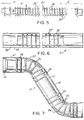
- FIG. 5 is a side elevational view of the inner pipe of FIG. 2 after formation of corrugations at selected locations therein.
- FIG. 6 is a side elevational view, partly in section, showing the assembled inner and outer pipes prior to bending.
- FIG. 7 is a side elevational view, partly in section showing the inner and outer pipes after bending.
- FIGS. 1 and 6 An exhaust pipe assembly in accordance with the subject invention is identified generally by the numeral 10 in FIGS. 1 and 6.
- the exhaust pipe assembly 10 extends circuitously through the engine compartment of a vehicle 12, and includes an upstream end 14 connected to the engine 16 and a downstream end 18 connected to a catalytic converter 20 disposed rearwardly of the engine compartment.
- the circuitous alignment of exhaust pipe assembly 10 may vary significantly from vehicle to vehicle, but typically will include a plurality of bends about non-parallel axes.
- the exhaust pipe assembly 10 includes an upstream tangent 21 extending from the upstream end 14.
- An upstream bend 22 is adjacent the upstream tangent 21 and is spaced from the upstream end 14 by distance "a".
- An intermediate tangent 23 extends from the upstream bend 22 to a downstream bend 24.
- a downstream tangent 25 of length "b" extends from the downstream bend 24 to the downstream end 18 and the catalytic converter 20.
- Exhaust pipe assembly 10 is operative to deliver exhaust gas from engine 16 to catalytic converter 20 prior to passage of the exhaust gas to other downstream parts of the exhaust system.
- the catalytic converter 20 functions to convert objectionable components of the exhaust gas into less objectionable forms.
- the catalyst in the converter 20 must be heated by the flowing exhaust gas to a predetermined temperature before it will perform properly.
- the exhaust pipe assembly 10 includes an inner pipe 30 for carrying the exhaust gas between the engine 16 and the catalytic converter 20.
- the inner pipe 30 has an outside diameter "c", which may be about 2.00 inches, and is formed from steel having a thickness "d" of between 0.012 inch and 0.020 inch.
- an alternate inner pipe 31 may be formed from laminated layers 31a and 31b having a combined thickness of 0.012-0.020 inch.
- the laminated inner pipe 31 will provide greater thermal insulation.
- the thickness "d" of the inner pipe 30, 31 (0.012-0.020 inch) is only about one-fourth the thickness of a typical prior art exhaust pipe. As a result, inner pipe 30 will heat very quickly, and will not function as a heat sink that could defer the lighting-off of catalytic converter 20 after a cold start.
- the thin steel from which inner pipe 30 is manufactured has the potential of being easily damaged in the harsh environment of a vehicular engine compartment. To prevent such damage, and to reduce heat dissipation due to connection in air circulating near the engine the pipe assembly 10 further includes an outer pipe 32 having an inside diameter "e", which may be about 2.75 inches. Thus, an enclosed annular air gap is defined between the inner and outer pipes to minimize heat dissipation from the inner pipe.
- the outer pipe 32 is formed from a steel having a material thickness "f" of 0.042-0.054 inch, as shown in FIG. 4. The greater thickness for outer pipe 32 provides structural support and protection for the thinner inner pipe 30.
- the exhaust pipe assembly 10 includes a plurality of bends 22, 24 and a corresponding plurality of tangents 21, 23 and 25 leading into or out of the respective bends 22, 24.
- the inner pipe 30 is provided with arrays of tangent corrugations 34 and arrays of bend corrugations 36.
- the tangent corrugations 34 define an outside diameter "g" which is equal to or slightly less than the inside diameter "e" of the outer pipe 32.
- the tangent corrugations 34 are disposed along inner pipe 30 to align with tangents 21, 23 and 25 on the exhaust pipe assembly 10.
- the bend corrugations 36 on the inner pipe 30 define an outside diameter "h" which is less than the diameter "g” for the tangent corrugations.
- the bend corrugations 36 are disposed along the inner pipe 30 at locations that will align with bends 22 and 24 in the exhaust pipe assembly 10.
- corrugations 34, 36 will depend upon several factors, including the dimensions of the respective pipes and the amount of bending required. Corrugations 34, 36 that are too close will provide adequate support, but will provide more heat transfer than desired. Corrugations 34, 36 that are too far apart will enable a desirably low heat transfer, but may not provide adequate structural support.
- a preferred spacing for corrugations 34, 36 at least in regions to be bent and in tangents adjacent to the bends preferably is between 0.5 inch and 2.5 inch. Exceptional structural support and heat insulation have been observed with corrugations spaced at approximately 0.75 inch at least in regions of bends.
- the inner pipe 30 is subject to repeated cycles of thermal expansion and contraction, and thus is exposed to thermal stresses and strains.
- the corrugations 34, 36 preferably are formed with a generally omega-shape.
- the omega-shape corrugations are well suited to repeated cycles of dimensional changes.
- the corrugated linearly aligned inner pipe 30 is inserted into the linear outer pipe 32.
- Tangent corrugations 34 will support inner pipe 30 substantially concentrically within outer pipe 32.
- Bend corrugations 36 are smaller than tangent corrugations 34, and hence will be spaced from outer pipe 32 prior to bending.
- the assembled inner and outer pipes 30 and 32 are then bent to an appropriate configuration as depicted generally in FIG. 1 and in FIG. 6. Compression bending of the pipe assembly 10 deforms the outer pipe 30 in regions of bends 22 and 24 without significantly deforming the outer pipe 32 along tangents. The deformation of the outer pipe 32 at bends 22 and 24 brings the outer pipe 32 into supporting engagement with the bend corrugations 36.
- the bend corrugations 36 are dimensioned to engage outer pipe 32 after bending, without significant crushing of bend corrugations 36.
- larger corrugations in areas of bends would be crushed by the bending process. Although crushing might not affect the structural integrity of the pipe assembly 10, it would significantly increase the surface area of contact, and hence would cause proportionally greater heat transfer from the inner pipe 30 to the outer pipe 32.
- the inner pipe 30 must be connected in gas-flow relationship to both the manifold of the engine and to a catalytic converter. As shown in FIG. 7, this connection can be achieved by inserting a ring 40 into the inner pipe 30 adjacent each end.
- the ring 40 may be spot welded in position and then is sized outwardly to achieve a force friction fit between the inner and outer pipes 30 and 32 adjacent the end.
- the inner and outer pipes 30 and 32 are then in contact with one another adjacent opposed ends of the pipe assembly 10 and can be securely welded to flanges or directly to the manifold or catalytic converter.
- the thin-walled inner pipe 30 of the exhaust pipe assembly 10 is heated quickly after a cold start, and hence does not function significantly as a heat sink for the exhaust gases traveling to catalytic converter 20. Heat dissipation through inner pipe 30 is minimized by the annular air insulation between the inner pipe 30 and the outer pipe 32 and by the very small contact area. As a result, the catalytic converter 16 lights-off quickly and achieves efficient operation during short drives following a cold start.
Abstract
Description
- Catalytic converters are used in vehicular exhaust systems to convert certain objectionable gases into environmentally more acceptable forms. The catalyst in the converter becomes operative or "lights-off" after it is heated to a specified temperature by the exhaust gases. Prior to lighting-off, the catalytic converter falls considerably short of complying with the air quality standards in most jurisdictions.
- The walls of the exhaust pipe leading from the engine to the catalytic converter are cold when the vehicle is first started. These cold pipes function as heat sinks which effectively draw heat from the exhaust gases traveling therethrough, and hence retard the lighting-off of the catalytic converter. The amount of heat dissipated in the walls of the pipe between the engine and the catalytic converter is a function of the thermal mass of the pipe, which in turn is a function of the pipe length, pipe diameter, surface area and pipe thickness.
- Catalytic converters typically are disposed as close as possible to the upstream end of an exhaust system where the exhaust gas is hottest. The upstream location is intended to accelerate the heating of the catalyst, and thereby achieves a quicker light-off. However, the engine compartment of a vehicle generally is too crowded to accommodate a catalytic converter and the required heat shields. Hence, the converter normally is disposed downstream of the engine compartment. Crowding in the engine compartment also requires a circuitous routing of the exhaust pipe extending from the engine manifold, through the engine compartment and to the catalytic converter. The circuitous routing of the exhaust pipe leading to the catalytic converter adds to the total length of the exhaust pipe. Thus, there is often a relatively long run of exhaust pipe between the manifold and the catalytic converter, even in instances where the catalytic converter can be placed fairly close to the engine compartment.
- Thin pipes draw less heat from exhaust gas than thicker pipes in view of the lower thermal mass of the thinner pipes. However, pipes in the engine compartment are subject to almost continuous vibration and frequent shock. Thin pipes are likely to behave poorly in response to vibration and shock. Additionally, normal engine maintenance requires workers to periodically access the engine compartment with tools. Forcible contact with a large tool can deform or otherwise damage a thin-walled pipe in the engine compartment. A deformation can have a significant effect on the flowing exhaust gas. Exhaust pipes undergo frequent thermal expansion and contraction which can exert significant stresses and strains on the thin pipe. Thus, automotive engineers are faced with competing demands of having a structurally adequate exhaust pipe and one that will enable the catalytic converter to light-off as quickly as possible.
- Heated components of an exhaust system often must be shielded at certain locations. For example, shields are used under exhaust system components that are close to the ground to avoid creating fires in nearby leaves or grass. Similarly, shields often are disposed between the exhaust system and parts of the vehicle that are sensitive to high temperatures.
- Many prior art heat shields are stamped from sheets of metal and are held in proximity to the exhaust system component by straps or welding. The prior art also includes air gap pipes to protectively separate the heated exhaust system component from adjacent parts of the vehicle or from combustible materials on the ground. Air gap pipes are relatively easy to manufacture for straight sections of an exhaust pipe. However, many prior art air gap pipe designs are difficult and costly to manufacture for circuitously aligned pipe sections. One costly approach for making a bent air gap pipe requires a linear inner pipe to be supported within a linear outer pipe by a filler material that has a lower melting point than either of the pipes. The linear assembly of inner and outer pipes and filler material is then bent into the required circuitous shape. The bent assembly is then heated sufficiently for the filler material to melt and be poured from the generally annular space between the inner and outer pipes. This approach is effective, but very costly and time consuming.
- Another very effective air gap pipe and method of manufacture is shown in U.S. Patent No. 4,501,302 and in U.S. Patent No. 4,656,713 both of which are assigned to the assignee of the subject invention. The air gap pipes shown in these two prior patents are made by initially bending the inner and outer pipes into the required shape. The outer pipe is then cut longitudinally in half and is sandwiched around the comparably bent inner pipe.
- Prior art air gap pipes perform their intended function as heat shields, but do not overcome the above described problems of the circuitous pipe in the engine compartment of a vehicle functioning as a heat sink which yields undesirable delays in lighting-off of a catalytic converter.
- In view of the above, it is an object of the subject invention to provide an exhaust pipe assembly enabling a quicker light-off of a catalytic converter.
- It is another object of the subject invention to provide a low thermal mass exhaust pipe exhibiting adequate structural integrity.
- A further object of the subject invention is to provide a catalytic converter assembly with an ability to light-off quickly.
- Still another object of the subject invention is to provide a method for manufacturing an exhaust pipe assembly for a catalytic converter.
- An additional object of the subject invention is to provide an air gap pipe assembly with low heat transfer from the inner pipe to the outer pipe.
- Yet another object of the subject invention is to provide an air gap pipe assembly that substantially avoids excessive stresses and strains in response to thermal expansion and contraction.
- The subject invention is directed to an exhaust pipe assembly that is particularly effective for achieving a very quick light-off of the catalytic converter.
- The pipe assembly may be complexly bent to deliver exhaust gas from the engine manifold, through the engine compartment, and to the catalytic converter. The particular circuitous shape will vary from vehicle to vehicle in accordance with the limited space available in the engine compartment, the configuration and orientation of the engine and the available space for locating and aligning the catalytic converter.
- The exhaust pipe assembly of the subject invention comprises an inner pipe formed from a thin low-thermal mass material and an outer pipe formed from a much thicker material to provide structural support for the assembly. In particular, the outer pipe may be formed from a material 2-4 times thicker than the inner pipe. For example, the inner pipe of the assembly may be formed from a material having a thickness of 0.012 inch - 0.020 inch. The outer pipe, on the other hand, may have a material thickness in the range of 0.042 inch - 0.054 inch. The inner pipe may be a laminated pipe with a total thickness in the stated range. Laminated pipes further enhance insulation and reduce heat transfer.
- The inner pipe is supported substantially concentrically in the outer pipe by a plurality of corrugations. The corrugations are formed at least at locations on the pipe assembly that are bent. Hence, the corrugations support the pipe both during the bending process and on the assembled exhaust pipe.
- Corrugations can be difficult to form on conventional pipes. However, the substantially thinner-than-normal inner pipe of the subject invention can be corrugated relatively easily. Despite the relative ease of corrugation, it is preferred that the number of corrugations be minimized in accordance with the required support during bending and the required support for the assembled pipe. Minimization of corrugations reduces the total length of pipe required, and hence reduces cost, weight and thermal mass of pipe leading to the catalytic converter. Minimization of corrugations also reduces the contact area between the inner and outer pipes, and hence achieves very low heat transfer from the inner pipe to the outer pipe. Although the corrugations can be disposed only at bend locations, a small number of corrugations may be disposed on tangents leading into and out of bends and in long linear sections to reduce vibrations and to contribute to structural support. Bent areas of pipes are collapsed somewhat during bending. This collapsing of the outer pipe could crush corrugations and thereby lead to larger contact areas and greater heat transfer between the inner and outer pipes. Thus, corrugations in each bend may define smaller heights than corrugations along tangents. The height of corrugations in bends may be selected to achieve a line of contact after bending without crushing any corrugation.
- The corrugations in the inner pipe preferably are configured to minimize stresses and strains in the metal of the inner pipe as the inner pipe undergoes repeated cycles of thermal expansion and contraction. Stresses and strains in the inner pipe can be substantially reduced by forming the corrugations into a substantially omega-shape.
- The subject invention also is directed to a method of manufacturing a pipe assembly. The method comprises the steps of providing a linear thin-walled inner pipe and a linear thick-walled outer pipe. The inner pipe is initially deformed to include arrays of radially aligned corrugations at locations selected to coincide at least with bends on the pipe assembly and on tangents leading to and from the pipe assembly. The linear corrugated inner pipe is then inserted into the outer pipe and the two pipes are bent simultaneously. The corrugations of the inner pipe provide the support during bending and also provide support for the bent pipe assembly. The method may proceed by connecting one end of the inner pipe to a catalytic converter.
- The pipe assembly of the subject invention offers several distinct advantages. First, exhaust gas traveling from the engine to the catalytic converter is exposed to only a low thermal mass material. The low-thermal mass inner pipe heats quickly, enabling more heat to be delivered quickly to the catalytic converter, and thereby enabling an early light-off of the catalyst. The outer pipe provides the necessary structural support for the assembly with a minimum contact area and a correspondingly low heat transfer. Additionally, the outer pipe provides an air insulation layer surrounding the inner pipe. As a result, heat from the thin-walled inner pipe is not dissipated to surrounding areas as quickly, and light-off time of the catalytic converter is further accelerated. The method of the subject invention also offers several manufacturing efficiencies. For example, the method of the subject invention entirely avoids the time consuming prior art approach of filling the annular space between the inner and outer pipes with a low-melting point filler prior to bending and then melting the filler from the space between pipes after bending.
- FIG. 1 is a perspective view of an exhaust system in accordance with the subject invention.
- FIG. 2 is an end elevational view of an inner pipe for the subject pipe assembly prior to corrugation and bending.
- FIG. 3 is an end elevational view of an alternate inner pipe.
- FIG. 4 is an end elevational view of the outer pipe prior to bending.
- FIG. 5 is a side elevational view of the inner pipe of FIG. 2 after formation of corrugations at selected locations therein.
- FIG. 6 is a side elevational view, partly in section, showing the assembled inner and outer pipes prior to bending.
- FIG. 7 is a side elevational view, partly in section showing the inner and outer pipes after bending.
- An exhaust pipe assembly in accordance with the subject invention is identified generally by the numeral 10 in FIGS. 1 and 6. The
exhaust pipe assembly 10 extends circuitously through the engine compartment of avehicle 12, and includes an upstream end 14 connected to theengine 16 and adownstream end 18 connected to acatalytic converter 20 disposed rearwardly of the engine compartment. The circuitous alignment ofexhaust pipe assembly 10 may vary significantly from vehicle to vehicle, but typically will include a plurality of bends about non-parallel axes. As shown in FIGS. 1 and 6, theexhaust pipe assembly 10 includes anupstream tangent 21 extending from the upstream end 14. Anupstream bend 22 is adjacent theupstream tangent 21 and is spaced from the upstream end 14 by distance "a". Anintermediate tangent 23 extends from theupstream bend 22 to adownstream bend 24. A downstream tangent 25 of length "b" extends from thedownstream bend 24 to thedownstream end 18 and thecatalytic converter 20. -
Exhaust pipe assembly 10 is operative to deliver exhaust gas fromengine 16 tocatalytic converter 20 prior to passage of the exhaust gas to other downstream parts of the exhaust system. Thecatalytic converter 20 functions to convert objectionable components of the exhaust gas into less objectionable forms. However, the catalyst in theconverter 20 must be heated by the flowing exhaust gas to a predetermined temperature before it will perform properly. - With reference to FIG. 2, the
exhaust pipe assembly 10 includes aninner pipe 30 for carrying the exhaust gas between theengine 16 and thecatalytic converter 20. Theinner pipe 30 has an outside diameter "c", which may be about 2.00 inches, and is formed from steel having a thickness "d" of between 0.012 inch and 0.020 inch. However, as shown in FIG. 3, an alternateinner pipe 31 may be formed fromlaminated layers 31a and 31b having a combined thickness of 0.012-0.020 inch. The laminatedinner pipe 31 will provide greater thermal insulation. The thickness "d" of theinner pipe 30, 31 (0.012-0.020 inch) is only about one-fourth the thickness of a typical prior art exhaust pipe. As a result,inner pipe 30 will heat very quickly, and will not function as a heat sink that could defer the lighting-off ofcatalytic converter 20 after a cold start. - The thin steel from which
inner pipe 30 is manufactured has the potential of being easily damaged in the harsh environment of a vehicular engine compartment. To prevent such damage, and to reduce heat dissipation due to connection in air circulating near the engine thepipe assembly 10 further includes anouter pipe 32 having an inside diameter "e", which may be about 2.75 inches. Thus, an enclosed annular air gap is defined between the inner and outer pipes to minimize heat dissipation from the inner pipe. Theouter pipe 32 is formed from a steel having a material thickness "f" of 0.042-0.054 inch, as shown in FIG. 4. The greater thickness forouter pipe 32 provides structural support and protection for the thinnerinner pipe 30. - As noted above, the
exhaust pipe assembly 10 includes a plurality ofbends tangents outer pipes inner pipe 30 is provided with arrays oftangent corrugations 34 and arrays ofbend corrugations 36. Thetangent corrugations 34 define an outside diameter "g" which is equal to or slightly less than the inside diameter "e" of theouter pipe 32. Thetangent corrugations 34 are disposed alonginner pipe 30 to align withtangents exhaust pipe assembly 10. The bend corrugations 36 on theinner pipe 30 define an outside diameter "h" which is less than the diameter "g" for the tangent corrugations. The bend corrugations 36 are disposed along theinner pipe 30 at locations that will align withbends exhaust pipe assembly 10. - The spacing between
corrugations Corrugations Corrugations corrugations - The
inner pipe 30 is subject to repeated cycles of thermal expansion and contraction, and thus is exposed to thermal stresses and strains. To better accommodate thermally generated dimensional changes and associated structural stress, thecorrugations - As depicted in FIG. 6, the corrugated linearly aligned
inner pipe 30 is inserted into the linearouter pipe 32.Tangent corrugations 34 will supportinner pipe 30 substantially concentrically withinouter pipe 32. Bend corrugations 36 are smaller thantangent corrugations 34, and hence will be spaced fromouter pipe 32 prior to bending. The assembled inner andouter pipes pipe assembly 10 deforms theouter pipe 30 in regions ofbends outer pipe 32 along tangents. The deformation of theouter pipe 32 atbends outer pipe 32 into supporting engagement with thebend corrugations 36. More particularly, the bend corrugations 36 are dimensioned to engageouter pipe 32 after bending, without significant crushing ofbend corrugations 36. In this regard, larger corrugations in areas of bends would be crushed by the bending process. Although crushing might not affect the structural integrity of thepipe assembly 10, it would significantly increase the surface area of contact, and hence would cause proportionally greater heat transfer from theinner pipe 30 to theouter pipe 32. - The
inner pipe 30 must be connected in gas-flow relationship to both the manifold of the engine and to a catalytic converter. As shown in FIG. 7, this connection can be achieved by inserting aring 40 into theinner pipe 30 adjacent each end. Thering 40 may be spot welded in position and then is sized outwardly to achieve a force friction fit between the inner andouter pipes outer pipes pipe assembly 10 and can be securely welded to flanges or directly to the manifold or catalytic converter. - In use, the thin-walled
inner pipe 30 of theexhaust pipe assembly 10 is heated quickly after a cold start, and hence does not function significantly as a heat sink for the exhaust gases traveling tocatalytic converter 20. Heat dissipation throughinner pipe 30 is minimized by the annular air insulation between theinner pipe 30 and theouter pipe 32 and by the very small contact area. As a result, thecatalytic converter 16 lights-off quickly and achieves efficient operation during short drives following a cold start. - While the invention has been described with respect to a preferred embodiment, it is apparent that various changes can be made without departing from the scope of the invention as defined by the appended claims.
Claims (10)
- An exhaust pipe assembly comprising:
a thin-walled inner pipe having at least one bend and tangents on opposed ends of said bend, said inner pipe being formed to include corrugations through said bend defining a selected outside diameter, said inner pipe further including at least one corrugation on each said tangent in proximity to said bend, said corrugations on said tangents defining outside diameters greater than the outside diameter of said corrugations through said bend; and
a thick-walled outer pipe having at least one bend and tangents on opposed ends of said bend, such that said outer pipe is disposed in surrounding relationship to said inner pipe, said tangents of said outer pipe defining an inside diameter approximately equal to the outside diameter of the corrugations on the tangents of said inner pipe, and said outer pipe being deformed in said bend to define an inside diameter approximately equal to the outside diameter defined by the corrugations through the bend of said inner pipe. - An exhaust pipe assembly as in claim 1, wherein the inner pipe defines a radial thickness of between 0.012-0.020 inch.
- An exhaust pipe assembly as in claim 2, wherein said inner pipe is a laminated pipe formed from at least two laminated layers.
- An exhaust pipe assembly as in claim 1, wherein the inner and outer pipes define radially thicknesses, the radial thickness of the outer pipe being approximately 2-4 times as great as the radial thickness of the inner pipe.
- An exhaust pipe assembly as in claim 1, wherein the inner and outer pipes comprise a plurality of bends and a plurality of tangents extending between said bends.
- An exhaust pipe assembly as in claim 5, wherein said inner pipe includes a plurality of corrugations on portions of said tangents extending between adjacent bends.
- An exhaust pipe assembly as in claim 6, wherein said corrugations define a selected spacing through said bends and a selected spacing on said tangents, the spacing between corrugations on said tangents being greater than the spacing between corrugations in said bends.
- An exhaust pipe assembly as in claim 1, wherein each said corrugation is of substantially omega-shape.
- An exhaust pipe assembly as in claim 1, wherein said inner and outer pipes each include opposed ends, at least one of said inner and outer pipes being deformed at said ends such that said inner and outer pipes are in secure circumferential engagement with one another at said ends.
- An exhaust pipe assembly as in claim 1, further comprising a catalytic converter connected to one end of the inner pipe, said thin inner pipe providing a low thermal mass and said outer pipe defining an air insulation, such that said catalytic converter lights off quickly.
Applications Claiming Priority (2)
| Application Number | Priority Date | Filing Date | Title |
|---|---|---|---|
| US53612 | 1993-04-27 | ||
| US08/053,612 US5390494A (en) | 1993-04-27 | 1993-04-27 | Pipe assembly for efficient light-off of catalytic converter |
Publications (2)
| Publication Number | Publication Date |
|---|---|
| EP0622531A1 true EP0622531A1 (en) | 1994-11-02 |
| EP0622531B1 EP0622531B1 (en) | 1997-04-02 |
Family
ID=21985428
Family Applications (1)
| Application Number | Title | Priority Date | Filing Date |
|---|---|---|---|
| EP93114492A Expired - Lifetime EP0622531B1 (en) | 1993-04-27 | 1993-09-09 | Pipe assembly for efficient light-off of catalytic converter |
Country Status (6)
| Country | Link |
|---|---|
| US (1) | US5390494A (en) |
| EP (1) | EP0622531B1 (en) |
| JP (1) | JPH0719041A (en) |
| CA (1) | CA2101202C (en) |
| DE (1) | DE69309436T2 (en) |
| ES (1) | ES2099877T3 (en) |
Cited By (3)
| Publication number | Priority date | Publication date | Assignee | Title |
|---|---|---|---|---|
| WO2005008118A1 (en) * | 2003-07-14 | 2005-01-27 | American Boa, Inc. | Double wall pipe assembly |
| DE10206066B4 (en) * | 2001-02-15 | 2005-05-19 | Avl List Gmbh | Internal combustion engine with an exhaust system |
| AT501385B1 (en) * | 2003-04-10 | 2007-12-15 | Avl List Gmbh | INTERNAL COMBUSTION ENGINE WITH AN EXHAUST SYSTEM |
Families Citing this family (29)
| Publication number | Priority date | Publication date | Assignee | Title |
|---|---|---|---|---|
| EP0662564B2 (en) * | 1994-01-07 | 2001-09-26 | J. Eberspächer GmbH & Co. | Air gap insulation exhaust pipe and method of construction |
| US5927344A (en) * | 1996-01-03 | 1999-07-27 | Nobileau; Philippe | Subsea flexible pipe |
| US5753339A (en) * | 1996-08-09 | 1998-05-19 | General Motors Corporation | Catalytic converter substrate with a plurality of cell groups having high and low thermal mass walls |
| DE19752773C2 (en) | 1997-11-28 | 1999-09-02 | Daimler Chrysler Ag | Method for producing an air gap-insulated exhaust manifold of a vehicle exhaust system |
| DE19752772C2 (en) * | 1997-11-28 | 1999-09-02 | Daimler Chrysler Ag | Process for producing an air-gap-insulated exhaust pipe provided with a branch connection |
| US6209319B1 (en) | 1998-09-28 | 2001-04-03 | Honda Giken Kogyo Kabushiki Kaisha | Pipe assembly having inner and outer pipes |
| US6199376B1 (en) | 1998-09-28 | 2001-03-13 | Honda Giken Kogyo Kabushiki Kaisha | Extension of exhaust manifold conduit into exhaust pipe |
| US6122911A (en) * | 1998-09-28 | 2000-09-26 | Honda Giken Kogyo Kabushiki Kaisha | Exhaust manifold pipe weld assembly |
| US5974784A (en) * | 1998-10-12 | 1999-11-02 | Nu-Chem, Inc. | Insulative shield, particularly for automotive exhaust components |
| DE10059195B4 (en) * | 2000-11-29 | 2006-04-06 | Benteler Automobiltechnik Gmbh | Arrangement for the treatment of the exhaust gases passing from a gasoline engine with direct injection |
| DE10157131C2 (en) * | 2001-11-21 | 2003-11-13 | Benteler Automobiltechnik Gmbh | Exhaust pipe and method for manufacturing an exhaust pipe |
| DE102005063539B4 (en) * | 2004-11-09 | 2012-09-06 | Denso Corporation | Method and device for producing a grooved pipe and its construction |
| US20070240408A1 (en) * | 2006-04-14 | 2007-10-18 | Ewa Environmental, Inc. | Particle burner including a catalyst booster for exhaust systems |
| US20080271448A1 (en) * | 2007-05-03 | 2008-11-06 | Ewa Environmental, Inc. | Particle burner disposed between an engine and a turbo charger |
| US7566423B2 (en) * | 2006-04-26 | 2009-07-28 | Purify Solutions, Inc. | Air purification system employing particle burning |
| US7500359B2 (en) * | 2006-04-26 | 2009-03-10 | Purify Solutions, Inc. | Reverse flow heat exchanger for exhaust systems |
| US20070278199A1 (en) * | 2006-04-14 | 2007-12-06 | Ewa Environmental, Inc. | Particle burning in an exhaust system |
| FI125709B (en) * | 2007-08-31 | 2016-01-15 | Retermia Oy | Apparatus and method for making a needle tube and needle tube |
| US7802428B2 (en) * | 2007-10-04 | 2010-09-28 | Honeywell International, Inc. | Turbocharger system subassemblies and associated assembly methods |
| US20090107117A1 (en) * | 2007-10-30 | 2009-04-30 | Ford Global Technologies, Llc | Diesel Engine Aftertreatment Control Operation with Waste Heat Recovery |
| DE102007052243A1 (en) * | 2007-11-02 | 2009-05-07 | Daimler Ag | Exhaust pipe component |
| DE102007062661A1 (en) * | 2007-12-24 | 2009-06-25 | J. Eberspächer GmbH & Co. KG | collector |
| DE102007062659A1 (en) * | 2007-12-24 | 2009-06-25 | J. Eberspächer GmbH & Co. KG | Exhaust manifold and related manufacturing process |
| US20100095682A1 (en) * | 2008-10-16 | 2010-04-22 | Lincoln Evans-Beauchamp | Removing Particulate Matter From Air |
| DE102013109199A1 (en) * | 2013-08-26 | 2015-02-26 | Witzenmann Gmbh | Conduction with arch structure |
| US20160101490A1 (en) * | 2014-10-08 | 2016-04-14 | Mersen Canada Toronto Inc. | Methods of manufacturing a complex heat pipe and a heat transfer plate including an opening therefor |
| WO2019092744A1 (en) * | 2017-11-09 | 2019-05-16 | Hero MotoCorp Limited | Exhaust system |
| CN111120063A (en) * | 2019-12-26 | 2020-05-08 | 东风越野车有限公司 | Forming process of special-shaped heat shield for exhaust tail pipe of off-road vehicle and heat shield |
| CN117020590A (en) * | 2023-10-08 | 2023-11-10 | 核工业西南物理研究院 | Manufacturing method of special pipe with interlayer |
Citations (4)
| Publication number | Priority date | Publication date | Assignee | Title |
|---|---|---|---|---|
| US2770313A (en) * | 1952-01-19 | 1956-11-13 | Int Harvester Co | Combination tail pipe and muffler |
| US3244254A (en) * | 1964-01-08 | 1966-04-05 | Compo Corp | Combination exhaust conduit and muffler |
| DE2406650A1 (en) * | 1973-02-14 | 1974-08-29 | Alfa Romeo Spa | INTERNAL HEAT-PROTECTED EXHAUST PIPES FOR COMBUSTION ENGINES AND TECHNOLOGICAL PROCESS FOR THEIR PRODUCTION |
| US4022019A (en) * | 1970-11-20 | 1977-05-10 | Alfa Romeo S.P.A. | Exhaust conveying system for internal combustion engines |
Family Cites Families (19)
| Publication number | Priority date | Publication date | Assignee | Title |
|---|---|---|---|---|
| US2913009A (en) * | 1956-07-16 | 1959-11-17 | Calumet & Hecla | Internal and internal-external surface heat exchange tubing |
| US3028289A (en) * | 1957-12-23 | 1962-04-03 | Fred T Roberts | Method of making flexible reinforced corrugated hose |
| US3133612A (en) * | 1960-07-06 | 1964-05-19 | Chrysler Corp | Sound deadening laminated engine exhaust pipe |
| US3404445A (en) * | 1964-09-14 | 1968-10-08 | Oldberg Mfg Company | Method of forming a sound attenuating and gas passage tube construction |
| US3730229A (en) * | 1971-03-11 | 1973-05-01 | Turbotec Inc | Tubing unit with helically corrugated tube and method for making same |
| US3847184A (en) * | 1972-10-05 | 1974-11-12 | A God | Metal pipe with spaced flexible portions |
| US4117201A (en) * | 1976-07-23 | 1978-09-26 | Fansteel Inc. | Corrosion and erosion resistant lined equipment |
| US4261671A (en) * | 1977-09-26 | 1981-04-14 | Shell Oil Company | Corrugated pipe for deepwater applications |
| US4345430A (en) * | 1979-11-15 | 1982-08-24 | Manville Service Corporation | Automotive catalytic converter exhaust system |
| NL8502327A (en) * | 1985-08-23 | 1987-03-16 | Wavin Bv | PLASTIC TUBE COMPRISING AN OUTDOOR HOUSING WITH RIDGES AND SMOOTH INTERIOR WALL AND METHOD FOR REPAIRING RESP. IMPROVE A SEWAGE TUBE. |
| US4854416A (en) * | 1986-06-09 | 1989-08-08 | Titeflex Corporation | Tuned self-damping convoluted conduit |
| US4793384A (en) * | 1986-02-11 | 1988-12-27 | Titeflex Corporation | Self-damping convoluted conduit |
| JPS6357882U (en) * | 1986-10-04 | 1988-04-18 | ||
| KR930009932B1 (en) * | 1987-12-09 | 1993-10-13 | 후지 꾸라 덴센 가부시끼가이샤 | Heat pipe and method of manufacturing the same |
| DE3803112A1 (en) * | 1988-02-03 | 1989-08-17 | Kabelmetal Electro Gmbh | LINE PIPE FOR TRANSPORTING DEEP-FREEZED MEDIA |
| US4966202A (en) * | 1988-11-14 | 1990-10-30 | Dayco Products, Inc. | Shape retention hose construction |
| US5069253A (en) * | 1990-01-08 | 1991-12-03 | Hadley Benjamin H | Flexible hose assembly |
| US4970351A (en) * | 1990-03-02 | 1990-11-13 | United Techologies Automotive, Inc. | Wiring harness conduit |
| US5163289A (en) * | 1991-10-08 | 1992-11-17 | Manville Corporation | Automotive exhaust system |
-
1993
- 1993-04-27 US US08/053,612 patent/US5390494A/en not_active Expired - Lifetime
- 1993-07-23 CA CA002101202A patent/CA2101202C/en not_active Expired - Fee Related
- 1993-08-19 JP JP5226483A patent/JPH0719041A/en active Pending
- 1993-09-09 DE DE69309436T patent/DE69309436T2/en not_active Expired - Fee Related
- 1993-09-09 EP EP93114492A patent/EP0622531B1/en not_active Expired - Lifetime
- 1993-09-09 ES ES93114492T patent/ES2099877T3/en not_active Expired - Lifetime
Patent Citations (4)
| Publication number | Priority date | Publication date | Assignee | Title |
|---|---|---|---|---|
| US2770313A (en) * | 1952-01-19 | 1956-11-13 | Int Harvester Co | Combination tail pipe and muffler |
| US3244254A (en) * | 1964-01-08 | 1966-04-05 | Compo Corp | Combination exhaust conduit and muffler |
| US4022019A (en) * | 1970-11-20 | 1977-05-10 | Alfa Romeo S.P.A. | Exhaust conveying system for internal combustion engines |
| DE2406650A1 (en) * | 1973-02-14 | 1974-08-29 | Alfa Romeo Spa | INTERNAL HEAT-PROTECTED EXHAUST PIPES FOR COMBUSTION ENGINES AND TECHNOLOGICAL PROCESS FOR THEIR PRODUCTION |
Cited By (3)
| Publication number | Priority date | Publication date | Assignee | Title |
|---|---|---|---|---|
| DE10206066B4 (en) * | 2001-02-15 | 2005-05-19 | Avl List Gmbh | Internal combustion engine with an exhaust system |
| AT501385B1 (en) * | 2003-04-10 | 2007-12-15 | Avl List Gmbh | INTERNAL COMBUSTION ENGINE WITH AN EXHAUST SYSTEM |
| WO2005008118A1 (en) * | 2003-07-14 | 2005-01-27 | American Boa, Inc. | Double wall pipe assembly |
Also Published As
| Publication number | Publication date |
|---|---|
| DE69309436D1 (en) | 1997-05-07 |
| CA2101202A1 (en) | 1994-10-28 |
| EP0622531B1 (en) | 1997-04-02 |
| DE69309436T2 (en) | 1997-08-21 |
| US5390494A (en) | 1995-02-21 |
| ES2099877T3 (en) | 1997-06-01 |
| CA2101202C (en) | 1995-11-21 |
| JPH0719041A (en) | 1995-01-20 |
Similar Documents
| Publication | Publication Date | Title |
|---|---|---|
| EP0622531B1 (en) | Pipe assembly for efficient light-off of catalytic converter | |
| US6555070B1 (en) | Exhaust component and method for producing an exhaust component | |
| CN1048537C (en) | Metallic honeycomb structure supported in an inner and an outer casing tube, especially a catalyst support | |
| KR100861737B1 (en) | Device for purifying exhaust gases of a motor vehicle and method for the production thereof | |
| US6343417B1 (en) | Process of manufacturing an air-gap-insulating exhaust elbow of a vehicle exhaust system | |
| US4250708A (en) | Exhaust double pipe of an internal combustion engine | |
| JPH10510899A (en) | Double-walled housing, especially for automotive exhaust catalytic reactors | |
| EP1091101B1 (en) | Exhaust pipe assembly of two-passage construction | |
| US5579639A (en) | Double walled exhaust pipe for an engine | |
| US20030180198A1 (en) | Catalyst assembly with a fixed catalyst carrier body | |
| US4713361A (en) | Metallic catalyst body having thermal radiation protection | |
| JP2003531994A (en) | Exhaust gas device of exhaust gas equipment, especially automotive catalyst device with modular structure | |
| US5094821A (en) | Exhaust gas cleaning device | |
| US4185463A (en) | Exhaust double pipe of an internal combustion engine | |
| JPH0481078B2 (en) | ||
| EP1032756B1 (en) | Catalytic converter and method for mounting of converter | |
| JP2003531333A (en) | Catalyst support with sleeve and shortened tubular jacket | |
| EP1036920A2 (en) | Monolith supporting structure for use in catalytic converter | |
| US6430811B1 (en) | Catalyst container | |
| JPH09234377A (en) | Manufacture of catalyst carrier and exhaust system member | |
| EP1136669B1 (en) | Catalyst carrier | |
| JP3248423B2 (en) | Exhaust manifold of internal combustion engine | |
| CZ295523B6 (en) | Catalytic reactor | |
| WO2019082639A1 (en) | Heat shield cover for exhausting device | |
| EP1504817B1 (en) | Metal carrier for exhaust emission control |
Legal Events
| Date | Code | Title | Description |
|---|---|---|---|
| PUAI | Public reference made under article 153(3) epc to a published international application that has entered the european phase |
Free format text: ORIGINAL CODE: 0009012 |
|
| AK | Designated contracting states |
Kind code of ref document: A1 Designated state(s): BE DE ES FR GB IT NL SE |
|
| 17P | Request for examination filed |
Effective date: 19950405 |
|
| 17Q | First examination report despatched |
Effective date: 19951228 |
|
| GRAG | Despatch of communication of intention to grant |
Free format text: ORIGINAL CODE: EPIDOS AGRA |
|
| GRAH | Despatch of communication of intention to grant a patent |
Free format text: ORIGINAL CODE: EPIDOS IGRA |
|
| GRAH | Despatch of communication of intention to grant a patent |
Free format text: ORIGINAL CODE: EPIDOS IGRA |
|
| GRAA | (expected) grant |
Free format text: ORIGINAL CODE: 0009210 |
|
| AK | Designated contracting states |
Kind code of ref document: B1 Designated state(s): BE DE ES FR GB IT NL SE |
|
| REF | Corresponds to: |
Ref document number: 69309436 Country of ref document: DE Date of ref document: 19970507 |
|
| REG | Reference to a national code |
Ref country code: ES Ref legal event code: FG2A Ref document number: 2099877 Country of ref document: ES Kind code of ref document: T3 |
|
| ITF | It: translation for a ep patent filed |
Owner name: SOCIETA' ITALIANA BREVETTI S.P.A. |
|
| ET | Fr: translation filed | ||
| PLBE | No opposition filed within time limit |
Free format text: ORIGINAL CODE: 0009261 |
|
| STAA | Information on the status of an ep patent application or granted ep patent |
Free format text: STATUS: NO OPPOSITION FILED WITHIN TIME LIMIT |
|
| 26N | No opposition filed | ||
| PGFP | Annual fee paid to national office [announced via postgrant information from national office to epo] |
Ref country code: NL Payment date: 20000620 Year of fee payment: 8 |
|
| PGFP | Annual fee paid to national office [announced via postgrant information from national office to epo] |
Ref country code: GB Payment date: 20000807 Year of fee payment: 8 |
|
| PGFP | Annual fee paid to national office [announced via postgrant information from national office to epo] |
Ref country code: SE Payment date: 20000901 Year of fee payment: 8 |
|
| PGFP | Annual fee paid to national office [announced via postgrant information from national office to epo] |
Ref country code: FR Payment date: 20000905 Year of fee payment: 8 |
|
| PGFP | Annual fee paid to national office [announced via postgrant information from national office to epo] |
Ref country code: ES Payment date: 20000925 Year of fee payment: 8 |
|
| PGFP | Annual fee paid to national office [announced via postgrant information from national office to epo] |
Ref country code: DE Payment date: 20000928 Year of fee payment: 8 |
|
| PGFP | Annual fee paid to national office [announced via postgrant information from national office to epo] |
Ref country code: BE Payment date: 20001010 Year of fee payment: 8 |
|
| PG25 | Lapsed in a contracting state [announced via postgrant information from national office to epo] |
Ref country code: GB Free format text: LAPSE BECAUSE OF NON-PAYMENT OF DUE FEES Effective date: 20010909 |
|
| PG25 | Lapsed in a contracting state [announced via postgrant information from national office to epo] |
Ref country code: SE Free format text: LAPSE BECAUSE OF NON-PAYMENT OF DUE FEES Effective date: 20010910 Ref country code: ES Free format text: LAPSE BECAUSE OF NON-PAYMENT OF DUE FEES Effective date: 20010910 |
|
| PG25 | Lapsed in a contracting state [announced via postgrant information from national office to epo] |
Ref country code: BE Free format text: LAPSE BECAUSE OF NON-PAYMENT OF DUE FEES Effective date: 20010930 |
|
| BERE | Be: lapsed |
Owner name: AP PARTS MFG CY Effective date: 20010930 |
|
| PG25 | Lapsed in a contracting state [announced via postgrant information from national office to epo] |
Ref country code: NL Free format text: LAPSE BECAUSE OF NON-PAYMENT OF DUE FEES Effective date: 20020401 |
|
| GBPC | Gb: european patent ceased through non-payment of renewal fee |
Effective date: 20010909 |
|
| PG25 | Lapsed in a contracting state [announced via postgrant information from national office to epo] |
Ref country code: DE Free format text: LAPSE BECAUSE OF NON-PAYMENT OF DUE FEES Effective date: 20020501 |
|
| EUG | Se: european patent has lapsed |
Ref document number: 93114492.7 |
|
| PG25 | Lapsed in a contracting state [announced via postgrant information from national office to epo] |
Ref country code: FR Free format text: LAPSE BECAUSE OF NON-PAYMENT OF DUE FEES Effective date: 20020531 |
|
| NLV4 | Nl: lapsed or anulled due to non-payment of the annual fee |
Effective date: 20020401 |
|
| REG | Reference to a national code |
Ref country code: FR Ref legal event code: ST |
|
| NLV4 | Nl: lapsed or anulled due to non-payment of the annual fee |
Effective date: 20020401 |
|
| REG | Reference to a national code |
Ref country code: ES Ref legal event code: FD2A Effective date: 20021011 |
|
| PG25 | Lapsed in a contracting state [announced via postgrant information from national office to epo] |
Ref country code: IT Free format text: LAPSE BECAUSE OF NON-PAYMENT OF DUE FEES;WARNING: LAPSES OF ITALIAN PATENTS WITH EFFECTIVE DATE BEFORE 2007 MAY HAVE OCCURRED AT ANY TIME BEFORE 2007. THE CORRECT EFFECTIVE DATE MAY BE DIFFERENT FROM THE ONE RECORDED. Effective date: 20050909 |