EP0622502A1 - False floor - Google Patents
False floor Download PDFInfo
- Publication number
- EP0622502A1 EP0622502A1 EP93103270A EP93103270A EP0622502A1 EP 0622502 A1 EP0622502 A1 EP 0622502A1 EP 93103270 A EP93103270 A EP 93103270A EP 93103270 A EP93103270 A EP 93103270A EP 0622502 A1 EP0622502 A1 EP 0622502A1
- Authority
- EP
- European Patent Office
- Prior art keywords
- grid support
- support bars
- raised floor
- grid
- flanges
- Prior art date
- Legal status (The legal status is an assumption and is not a legal conclusion. Google has not performed a legal analysis and makes no representation as to the accuracy of the status listed.)
- Ceased
Links
Images


Classifications
-
- E—FIXED CONSTRUCTIONS
- E04—BUILDING
- E04F—FINISHING WORK ON BUILDINGS, e.g. STAIRS, FLOORS
- E04F15/00—Flooring
- E04F15/02—Flooring or floor layers composed of a number of similar elements
- E04F15/024—Sectional false floors, e.g. computer floors
- E04F15/02447—Supporting structures
- E04F15/02452—Details of junctions between the supporting structures and the panels or a panel-supporting framework
-
- E—FIXED CONSTRUCTIONS
- E04—BUILDING
- E04F—FINISHING WORK ON BUILDINGS, e.g. STAIRS, FLOORS
- E04F15/00—Flooring
- E04F15/02—Flooring or floor layers composed of a number of similar elements
- E04F15/024—Sectional false floors, e.g. computer floors
- E04F15/02447—Supporting structures
- E04F15/02458—Framework supporting the panels
Definitions
- the invention relates to a raised floor with a load-bearing substructure made of footrests and grid support rods for floor slabs fixed to them, each of which consists of a metallic tub with a filling made of a mineral substance, preferably anhydrite, each tub above by a circumferential, outwardly projecting Flange is limited, so that there are cavities laterally between the installed floor slabs.
- the invention is therefore based on the object of significantly increasing the load-bearing capacity of a raised floor of the type mentioned above, especially in the edge region of its floor slabs, in comparison with the prior art.
- the above object is achieved in that grid support bars or parts of grid support bars are arranged in the cavities between the base plates in such a way that they support the flanges of the base plate trays.
- the flanges of the floor slab trays are supported in the finished double floor on the grid support bars or on parts of these grid support bars, whereby the resilience of the edge areas of the double floor slabs laid in abutment is considerably improved compared to the prior art.
- the grid support bars are supported on the top plates of the footrests of the load-bearing substructure.
- the cantilevered base plates can then also be placed with their corners on the head plates of the footrests.
- Embodiments of the invention emerge from the subclaims. So it is advantageous for noise insulation when using the double floor if a sound-absorbing material, for example, between the flanges of the base plate trays and the grid support bars Plastic, cork or the like is arranged.
- the plastic material can, for example, simply be sprayed on the underside of the flanges and / or on the top of the grid support rods. If cork or similar material is used as the sound-absorbing material, this is expediently attached in strip form to the top of the grid support rods, for example simply by means of an adhesive.
- plastic profiles are arranged or fitted onto the flanges of the base plate tubs, which are seated on the grid support bars. Such plastic profiles then serve, as is known per se, both in the manufacturing process and in the transport of the base plates as edge protection.
- the plastic profiles overlap the grid support bars with an angular profile, it is ensured that the side walls of the base plates maintain a distance from the grid support bars. This also prevents noise when using the raised floor, which would otherwise arise due to friction between metal and metal.
- the load-bearing capacity of the raised floor is further increased overall if, according to yet another embodiment of the invention, the grid support bars arranged in the cavities between the floor boards are arranged on a further system of grid support bars which extends below the floor boards. As is known per se, the base plates can then be supported on the edge regions of their underside on these grid support rods, which are at a lower level.
- the grid support rods preferably have a rectangular hollow profile.
- the grid support rods have a rectangular hollow profile that is slit lengthways on the top or bottom.
- the grid support rods can also have a hat-shaped cross-sectional profile or a part with such a cross-sectional profile. Such is attached with its horizontal legs to the head plates of the footrests, e.g. screwed on.
- the part of the grid support rods with the hat-shaped cross-sectional profile is supplemented on both sides by downwardly projecting legs with an angular cross-sectional profile, grid support rods are advantageously obtained which support both the circumferential, outwardly projecting flanges on the base plates and allow the floor slabs to be supported on the edge areas of their bottom or underside.
- the grid support rods can advantageously be guided continuously over the footrests to support the flanges of the base plates, while the downwardly projecting legs of these grid support rods are inserted into corresponding slots in the head plates of the footrests.
- the exemplary embodiments described below relate to raised floors, which consist of the floor slabs and a substructure supporting these floor slabs put together.
- the latter has footrests set up on a building raw floor in the grid of the floor slabs and grid support rods fixed to these footrests.
- the support tube 11 is shown partially in all of the exemplary embodiments in FIGS. 1-12, which supports a head plate 12 at its upper end.
- the head plates 12 of all the exemplary embodiments according to FIGS. 1-12 are preferably of the same design and can be used in a variety of ways, which will be explained later.
- the base plates 15 are so-called self-supporting base plates, which in the exemplary embodiments according to FIGS. 1-6 are only supported with their corners on the head plates 12 of the footrests 10.
- Loads occurring in the edge region of the floor slabs 15 can therefore be removed from the grid support rods 19 via the footrests 10 onto the relevant unfinished building floor.
- the ends of these grid support rods 19 are mitred and are pushed together in the middle of each head plate 12 as shown in FIG. 2.
- Each grid support rod 19 also has a bore 20 on its underside near the rod ends, into which, when the grid support rods 19 are placed on the head plates 12 of the footrests, 10 protrusions 21 are inserted, which are arranged on the head plates 12.
- the projections 21 are punched out of the head plates 12, for example in the form of claws, and are bent upwards accordingly, as can be seen from the figures.
- the projections 21 can also consist, for example, of bolts which are fastened to the head plate 12.
- An annular sound-absorbing element 22 is provided between the head plate 12 of each footrest 10 and the underside of the four bottom plates 15 supported by their corners on a head plate 12.
- the circumferential flanges 14 of the base plates 15 are in direct contact with the top of the grid support rods 19, which means that metal lies on metal. This state can lead to noise formation and such can be avoided simply by introducing a sound-absorbing material between the flanges 14 and the grid support rods 19.
- 1a and 1b show examples of corresponding measures.
- the 1a is a plastic layer 23 of uniform thickness, for example, molded onto the underside of the circumferential flanges 14 on the tubs 13.
- a plastic or cork strip 24 is attached to the top of the grid support rods 19, for example by gluing, for the same purpose.
- FIGS. 4-6 This embodiment corresponds essentially to that of FIGS. 1-3 and the same parts are therefore identified by the same reference numerals, which also applies to the embodiments according to FIGS. 7-9 and 10-12.
- the grid support rods 19 which run in the cavities 18 between the side walls of the base plates 15 and are anchored to the head plates 12 of the footrests 10 as in the previous exemplary embodiment also have a rectangular hollow profile, but with a somewhat lower height than in the exemplary embodiment according to FIGS. 1-3.
- 13 plastic profiles 25 are attached to the circumferential flanges 14 of the base plate trays and e.g. fixed by gluing.
- plastic profiles 25 are designed so that they sit on the grid support bars 19 when the floor panels 15 are laid and overlap the grid support bars 19 laterally somewhat with an angular profile 26.
- the flanges 14 of the troughs 13 of the base plates 15 are consequently supported here via the plastic profiles 25 on the grid support rods 19, which in turn are supported on the head plates 12 of the footrests 10 and fixed to them.
- FIGS. 7-9 corresponds to that of FIGS. 4-6, but are in the Cavities 18 between the base plates 15 arranged grid support bars 19 supported on further grid support bars 27.
- the system of the grid support bars 27 is consequently arranged at a lower level than that of the grid support bars 19.
- the embodiment according to FIGS. 7-9 serves, if necessary, to further increase the load-bearing capacity of the substructure and thus of the raised floor.
- the "lower" grid support rods 27 also allow the base plates 15 to be supported in the edge region of their floors, in addition to the support of the flanges 14 via the plastic profiles 25 on the grid support rods 19.
- the grid support rods 19 and 27 are fixed to the projections 21 of the head plates 12,
- the grid support rods 27 of the lower system have corresponding bores 28 in their upper wall, through which the claw-shaped projections 21 fit when the grid support rods 27 are placed on the head plates 12 of the footrests 10 and inserted into slots 33 (FIG. 5 ).
- the grid support rods 27, which likewise consist of a rectangular hollow profile, are dimensioned correspondingly wide in order to enable the above-mentioned edge-side support of the base plates 15.
- the two systems of grid support rods 19 and 27 are replaced by a single system of grid support rods 29, the cross-sectional profile of which allows the base plates 15 in the edge region of their underside and on the To support flanges 14 of their tubs 13.
- These grid support rods 29 have an upper part 30 with a hat-shaped cross-sectional profile, which is supplemented on both sides or on both longitudinal sides by downwardly projecting legs 31 with an angular cross-sectional profile.
- the upper part with the hat-shaped cross-sectional profile is with its horizontal sections attached to the head plate 12 by means of screws 32.
- a system of grid support bars can be used, which have only a hat-shaped cross-sectional profile (without leg 31).
- the longitudinal extension of the part 30 of the grid support rods 29 projecting into the cavities 18 between the base plates 15 is greater than that of the "lower" remaining part with the legs 31, the ends of the legs 31 being mitred are, so that you can, as Fig. 11 shows, seamlessly put together in the center of the head plate 12.
- the legs 31 extend with their vertical sections through slots 33 in the head plate 12 of each footrest 10 (FIGS. 5, 10 and 11).
- the projections 21 on the head plate 12 are ineffective in the embodiment according to FIGS. 10-12, i.e. they extend into the cavities of the upper parts 30 of the grid support rods 29.
- the head plate 12 is designed so that the footrests 10 equipped with it can be used in all embodiments of FIGS. 1-12 .
- the reference bores 34 denote the threaded bores for receiving the screws 32.
- the bottom plates 15 are supported by the interposition of sound-absorbing strips 22 in the edge region of their underside on the horizontal sections of the upper part 30 of the grid support rods 29, which in turn rest on the top plate 12.
- the flanges 14 of the trays 13 of the base plates 15 are supported on the Plastic profiles 25, the arrangement and design of which corresponds to the exemplary embodiments according to FIGS. 4-6 or 7-9, on the upper parts 30 of the grid support rods 29.
- the grid support bars 19 with a rectangular hollow profile of the exemplary embodiments according to FIGS. 1-9 could also be replaced by grid support bars (not shown) with a rectangular hollow profile which is slit lengthways on the top or bottom. Such profiles could then also be used, for example, to accommodate electrical cables or the like.
- plastic profiles 25 are arranged on the flanges 14 of the troughs 13 of the base plates 15 in the exemplary embodiments according to FIGS. 4-6 or 7-9 or 10-12, the latter can also be replaced by sound-absorbing means, as shown, for example, in FIGS 1a and 1b are shown.
- the overall height of the grid support bars 19 or the upper part 30 of the grid support bars 29 would then have to be increased accordingly.
Landscapes
- Engineering & Computer Science (AREA)
- Architecture (AREA)
- General Engineering & Computer Science (AREA)
- Civil Engineering (AREA)
- Structural Engineering (AREA)
- Floor Finish (AREA)
Abstract
Description
Die Erfindung bezieht sich auf einen Doppelboden mit einer tragenden Unterkonstruktion aus Fußstützen und an diesen fixierten Rastertragstäben für Bodenplatten, welche jeweils aus einer metallischen Wanne mit einer Füllung aus einem mineralischen Stoff, vorzugsweise Anhydrit bestehen, wobei jede Wanne oben durch einen umlaufenden, nach außen ragenden Flansch begrenzt ist, wodurch seitlich zwischen den verlegten Bodenplatten Hohlräume vorhanden sind.The invention relates to a raised floor with a load-bearing substructure made of footrests and grid support rods for floor slabs fixed to them, each of which consists of a metallic tub with a filling made of a mineral substance, preferably anhydrite, each tub above by a circumferential, outwardly projecting Flange is limited, so that there are cavities laterally between the installed floor slabs.
Es ist bekannt (DE-PS 38 33 875), bei Doppelböden die Bodenplatten im Randbereich ihrer Unterseite auf Rastertragstäben aufzulagern, die an den Kopfplatten von Fußstützen einer tragenden Unterkonstruktion des Doppelbodens angeschlossen sind. Der Anschluß der Rastertragstäbe an den Fußstützen erfolgt entweder durch Schlitz-Laschenverbindungen oder mittels Schrauben. Diese Rastertragstäbe erhöhen die Belastbarkeit des Doppelbodens im Vergleich zu jenen Ausführungen, bei welchen die Bodenplatten nur mit ihren Ecken auf den Kopfplatten der Fußstützen aufgelagert sind. Wenn es sich jedoch bei den Bodenplatten um eine Ausführung handelt, die aus einer metallischen Wanne mit einer Füllung aus z.B. Anhydrit besteht, und die metallische Wanne oben durch einen umlaufenden, nach außen ragenden Flansch begrenzt ist, ergeben sich nach wie vor im Randbereich dieser Doppelbodenplatten insbesondere bei Punktbelastung Probleme.It is known (DE-PS 38 33 875) to support the floor slabs in the edge region of their underside on grid support bars in double floors, which are connected to the head plates of footrests of a supporting substructure of the double floor. The grid support rods are connected to the footrests either by means of slotted link connections or by means of screws. These grid support bars increase the resilience of the double floor compared to those versions in which the base plates are only supported with their corners on the head plates of the footrests. However, if the base plates are made from a metal tray with a filling of e.g. anhydrite, and the top of the metal tray is delimited by a circumferential, outwardly projecting flange, this still results in the edge area of these raised floor panels especially with point loading Problems.
Es ist zwar bekannt (DE-OS 37 31 126), die nach außen ragenden, umlaufenden Flansche an den Wannen solcher Doppelbodenplatten mit einem Kunststoffprofil abzudecken bzw. in ein Kunststoffprofil einzubetten. Zu einer höheren Belastbarkeit der Randbereiche dieser Doppelbodenplatten tragen diese Kunststoffprofile jedoch praktisch nicht bei.It is known (DE-OS 37 31 126) to cover the outwardly projecting, circumferential flanges on the trays of such double floor panels with a plastic profile or to embed them in a plastic profile. However, these plastic profiles practically do not contribute to a higher load capacity of the edge areas of these raised floor panels.
Der Erfindung liegt daher die Aufgabe zugrunde, die Belastbarkeit eines Doppelbodens der eingangs bezeichneten Art vor allem im Randbereich seiner Bodenplatten im Vergleich zum Stand der Technik deutlich zu erhöhen.The invention is therefore based on the object of significantly increasing the load-bearing capacity of a raised floor of the type mentioned above, especially in the edge region of its floor slabs, in comparison with the prior art.
Gemäß der Erfindung wird obige Aufgabe dadurch gelöst, daß in den Hohlräumen zwischen den Bodenplatten Rastertragstäbe oder Teile von Rastertragstäben derart angeordnet sind, daß sie die Flansche der Bodenplatten-Wannen abstützen. Mit anderen Worten, die Flansche der Bodenplatten-Wannen sind beim fertigen Doppelboden auf den Rastertragstäben bzw. auf Teile dieser Rastertragstäbe aufgelagert, wodurch die Belastbarkeit der Randbereiche der auf Stoß verlegten Doppelbodenplatten im Vergleich zum Stand der Technik erheblich verbessert wird. Die Rastertragstäbe sind dabei auf den Kopfplatten der Fußstützen der tragenden Unterkonstruktion aufgelagert. Bei einer einfachen Version der Erfindung können die Bodenplatten in freitragender Ausführung dann mit ihren Ecken gleichfalls auf den Kopfplatten der Fußstützen aufgesetzt sein.According to the invention the above object is achieved in that grid support bars or parts of grid support bars are arranged in the cavities between the base plates in such a way that they support the flanges of the base plate trays. In other words, the flanges of the floor slab trays are supported in the finished double floor on the grid support bars or on parts of these grid support bars, whereby the resilience of the edge areas of the double floor slabs laid in abutment is considerably improved compared to the prior art. The grid support bars are supported on the top plates of the footrests of the load-bearing substructure. In a simple version of the invention, the cantilevered base plates can then also be placed with their corners on the head plates of the footrests.
Ausgestaltungen der Erfindung gehen aus den Unteransprüchen hervor. So ist es zur Geräuschdämmung bei der Benutzung des Doppelbodens vorteilhaft, wenn zwischen den Flanschen der Bodenplatten-Wannen und den Rastertragstäben ein schalldämmendes Material, z.B. Kunststoff, Kork oder dergleichen, angeordnet ist. Das Kunststoffmaterial kann z.B. an der Unterseite der Flansche und/oder an der Oberseite der Rastertragstäbe einfach aufgespritzt sein. Wird Kork oder ähnliches Material als schalldämmender Stoff eingesetzt, wird dieses zweckmäßig in Streifenform an der Oberseite der Rastertragstäbe z.B. einfach mittels eines Klebers befestigt.Embodiments of the invention emerge from the subclaims. So it is advantageous for noise insulation when using the double floor if a sound-absorbing material, for example, between the flanges of the base plate trays and the grid support bars Plastic, cork or the like is arranged. The plastic material can, for example, simply be sprayed on the underside of the flanges and / or on the top of the grid support rods. If cork or similar material is used as the sound-absorbing material, this is expediently attached in strip form to the top of the grid support rods, for example simply by means of an adhesive.
Nach einer weiteren Ausgestaltung der Erfindung sind zur Erzielung des vorgenannten Schalldämmungseffekts auf den Flanschen der Bodenplatten-Wannen Kunststoffprofile angeordnet bzw. aufgesteckt, welche auf den Rastertragstäben aufsitzen. Solche Kunststoffprofile dienen dann gleichzeitig, wie an sich bekannt, sowohl im Herstellungsprozess, als auch beim Transport der Bodenplatten als Kantenschutz.According to a further embodiment of the invention, in order to achieve the abovementioned sound insulation effect, plastic profiles are arranged or fitted onto the flanges of the base plate tubs, which are seated on the grid support bars. Such plastic profiles then serve, as is known per se, both in the manufacturing process and in the transport of the base plates as edge protection.
Wenn nach noch einer weiteren Ausgestaltung der Erfindung die Kunststoffprofile die Rastertragstäbe mit einem winkelförmigen Profil übergreifen, ist sichergestellt, daß die Seitenwände der Bodenplatten einen Abstand von den Rastertragstäben einhalten. Auch dadurch wird bei der Benutzung des Doppelbodens eine Geräuschbildung verhindert, die sonst durch Reibung von Metall an Metall enstehen würde.If, according to yet another embodiment of the invention, the plastic profiles overlap the grid support bars with an angular profile, it is ensured that the side walls of the base plates maintain a distance from the grid support bars. This also prevents noise when using the raised floor, which would otherwise arise due to friction between metal and metal.
Die Belastbarkeit des Doppelbodens wird insgesamt weiter erhöht, wenn nach noch einer weiteren Ausführungsform der Erfindung die in den Hohlräumen zwischen den Bodenplatten angeordneten Rastertragstäbe auf einem weiterem System von Rastertragstäben angeordnet sind, welches sich unterhalb der Bodenplatten erstreckt. Auf diese auf einem tieferen Niveau liegenden Rastertragstäbe können dann, wie an sich bekannt, die Bodenplatten an den Randbereichen ihrer Unterseite aufgelagert werden.The load-bearing capacity of the raised floor is further increased overall if, according to yet another embodiment of the invention, the grid support bars arranged in the cavities between the floor boards are arranged on a further system of grid support bars which extends below the floor boards. As is known per se, the base plates can then be supported on the edge regions of their underside on these grid support rods, which are at a lower level.
Die Rastertragstäbe weisen vorzugsweise ein Rechteckhohlprofil auf.The grid support rods preferably have a rectangular hollow profile.
Bei einer weiteren Version der Erfindung weisen die Rastertragstäbe ein an der Oberseite oder Unterseite längs geschlitztes Rechteckhohlprofil auf.In a further version of the invention, the grid support rods have a rectangular hollow profile that is slit lengthways on the top or bottom.
Die Rastertragstäbe können aber auch ein hutförmiges Querschnittprofil oder einen Teil mit einem solchen Querschnittsprofil aufweisen. Ein solches wird mit seinen horizontalen Schenkeln an den Kopfplatten der Fußstützen befestigt, z.B. angeschraubt.The grid support rods can also have a hat-shaped cross-sectional profile or a part with such a cross-sectional profile. Such is attached with its horizontal legs to the head plates of the footrests, e.g. screwed on.
Wenn nach noch einer weiteren Ausgestaltung der Erfindung der Teil der Rastertragstäbe mit dem hutförmigen Querschnittsprofil beidseitig durch nach unten ragende Schenkel mit einem winkelförmigen Querschnittsprofil ergänzt ist, erhält man vorteilhaft Rastertragstäbe, die sowohl die umlaufenden, nach außen ragenden Flansche an den Bodenplatten unterstützen, als auch eine Auflagerung der Bodenplatten an den Randbereichen ihrer Boden- oder Unterseite ermöglichen.If, according to yet another embodiment of the invention, the part of the grid support rods with the hat-shaped cross-sectional profile is supplemented on both sides by downwardly projecting legs with an angular cross-sectional profile, grid support rods are advantageously obtained which support both the circumferential, outwardly projecting flanges on the base plates and allow the floor slabs to be supported on the edge areas of their bottom or underside.
Wenn nach noch einer weiteren Ausgestaltung der Erfindung die Längserstreckung der in die Hohlräume zwischen den Bodenplatten ragenden Teile mit dem hutförmigen Querschnittprofil größer als die des restlichen Teils dieser Rastertragstäbe ist, können die Rastertragstäbe vorteilhaft zur Abstützung der Flansche der Bodenplatten durchgehend über die Fußstützen geführt werden, während die nach unten ragenden Schenkel dieser Rastertragstäbe in entsprechende Schlitze in den Kopfplatten der Fußstützen eingesteckt werden.If, according to yet another embodiment of the invention, the longitudinal extension of the parts with the hat-shaped cross-sectional profile protruding into the cavities between the base plates is larger than that of the remaining part of these grid support rods, the grid support rods can advantageously be guided continuously over the footrests to support the flanges of the base plates, while the downwardly projecting legs of these grid support rods are inserted into corresponding slots in the head plates of the footrests.
Die Erfindung wird anschließend anhand der Zeichnungen von Ausführungsbeispielen erläutert. Es zeigen:
- Fig. 1
- einen Ausschnitt aus einem Doppelboden in Bereich einer Fußstütze mit erfindungsgemäß angeordneten Rastertragstäben, aufsitzend auf den Kopfplatten der Fußstützen (Schnitt A-A in Fig. 2);
- Fig. 1a und Fig. 1b
- Teilschnittansichten je eines Rastertragstabs, auf den sich die Flansche zweier benachbarter Bodenplatten abstützen, und zwar unter Zwischenschaltung unterschiedlicher schalldämmender Materialien;
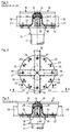
- Fig. 2
- eine Draufsicht auf die in Fig. 1 gezeigte Fußstütze mit Teilen der Rastertragstäbe, jedoch ohne Bodenplatten;
- Fig. 3
- eine der Fig. 1 ähnliche Teil-Schnittansicht entlang der Linie B-B in Fig. 2, und zwar bei auf dieser Fußstütze aufgelagerten Bodenplatten;
- Fig. 4
- eine der Fig. 1 ähnliche Teil-Schnittansicht, jedoch mit auf den nach außen ragenden Flanschen der Wannen der Bodenplatten angeordneten Kunststoffprofilen, über die sich die Flansche auf den Rastertragstäben abstützen (Schnitt A-A in Fig. 5);
- Fig. 5
- eine Draufsicht auf die Fußstütze der Fig. 4, mit Teilen der Rastertragstäbe, jedoch ohne Bodenplatten;
- Fig. 6
- eine Teil-Schnittansicht entlang der Linie B-B in Fig. 5, jedoch bei aufgelagerten Bodenplatten;
- Fig. 7
- einen der Fig. 1 ähnlichen Ausschnitt aus einem Doppelboden im Bereich einer Fußstütze, die nur teilweise gezeigt ist, wobei bei dieser Version zwei übereinander angeordnete Systeme von Rastertragstäben vorgesehen sind (Schnitt A-A in Fig. 8);
- Fig. 8
- eine Draufsicht auf die Fußstütze der Fig. 7 mit Teilen der Rastertragstäbe, ohne Bodenplatten;
- Fig. 9
- eine Teil-Schnittansicht entlang der Linie B-B in Fig. 8 bei auf der Fußstütze aufgelagerten Bodenplatten;
- Fig. 10
- einen weiteren der Fig. 1 ähnlichen Ausschnitt aus einem Doppelboden im Bereich einer Fußstütze, die nur teilweise gezeigt ist, mit modifizierten Rastertragstäben, von welchen nur ein oberer Teil in den Hohlräumen seitlich zwischen benachbarten Bodenplatten verläuft, und zwar entlang der Schnittlinie B-B in Fig. 11;
- Fig. 11
- eine Draufsicht auf die Fußstütze der Fig. 10 mit Teilen der modifizierten Rastertragstäbe, ohne aufgelagerte Bodenplatten und
- Fig. 12
- eine Teil-Schnittansicht entlang der Linie A-A in Fig. 11, wobei hier die Bodenplatten in strichpunktierten Linien angedeutet sind.
- Fig. 1
- a section of a double floor in the area of a footrest with grid support bars arranged according to the invention, sitting on the head plates of the footrests (section AA in Fig. 2);
- Fig. 1a and Fig. 1b
- Partial sectional views of a grid support bar, on which the flanges of two adjacent floor slabs are supported, with the interposition of different sound-absorbing materials;
- Fig. 2
- a plan view of the footrest shown in Figure 1 with parts of the grid support rods, but without base plates.
- Fig. 3
- a partial sectional view similar to Figure 1 along the line BB in Figure 2, namely with base plates supported on this footrest;
- Fig. 4
- a partial sectional view similar to Figure 1, but with plastic profiles arranged on the outwardly projecting flanges of the troughs of the base plates, by means of which the flanges are supported on the grid support bars (section AA in Figure 5);
- Fig. 5
- a plan view of the footrest of Figure 4, with parts of the grid support rods, but without base plates.
- Fig. 6
- a partial sectional view along the line BB in Fig. 5, but with supported base plates;
- Fig. 7
- a section similar to FIG. 1 from a raised floor in the area of a footrest, which is only partially shown, two versions of grid support rods being arranged one above the other being provided in this version (section AA in FIG. 8);
- Fig. 8
- a plan view of the footrest of Figure 7 with parts of the grid support bars, without base plates.
- Fig. 9
- a partial sectional view taken along line BB in Figure 8 with the base plates supported on the footrest;
- Fig. 10
- another section similar to FIG. 1 from a double floor in the area of a footrest, which is only partially shown, with modified grid support bars, of which only an upper part runs laterally in the cavities between adjacent floor panels, namely along the section line BB in FIG. 11;
- Fig. 11
- a plan view of the footrest of FIG. 10 with parts of the modified grid support bars, without supported base plates and
- Fig. 12
- a partial sectional view taken along line AA in Fig. 11, wherein the bottom plates are indicated in dash-dotted lines.
Die nachstehend beschriebenen Ausführungsbeispiele betreffen Doppelböden, welche sich aus den Bodenplatten und einer diese Bodenplatten tragenden Unterkonstruktion zusammensetzen. Letztere weist auf einen Gebäude-Rohboden im Raster der Bodenplatten aufgestellte Fußstützen und an diesen Fußstützen fixierte Rastertragstäbe auf. Von den höhenverstellbaren Fußstützen 10 ist in sämtlichen Ausführungsbeispielen der Figuren 1-12 nur das Stützenrohr 11 teilweise gezeigt, welches an seinem oberen Ende eine Kopfplatte 12 trägt. Die Kopfplatten 12 aller Ausführungsbeispiele nach den Fig. 1-12 sind vorzugsweise gleichartig ausgebildet und entsprechend vielseitig einsetzbar, was noch erläutert wird. Ebenso sind die Bodenplatten 15 aller Ausführungsbeispiele der Fig. 1 - 12 gleich aufgebaut und sie bestehen jeweils aus einer tiefgezogenen Wanne 13, vorzugsweise aus verzinktem Stahlblech, mit einer Füllung 16 aus einem ausgehärteten mineralischen Material, vorzugsweise Anhydrit, und einem Deckbelag 17, z.B. einem Teppichboden. Zwischen der Füllung 16 und der Wanne 13 ist ein statischer Verbund vorhanden. Die Wannen 13 sind oben durch einen umlaufenden, nach außen ragenden Flansch 14 begrenzt. Es handelt sich bei den Bodenplatten 15 um sogenannte freitragende Bodenplatten, welche bei den Ausführungsbeispielen nach den Fig. 1-6 lediglich mit ihren Ecken auf den Kopfplatten 12 der Fußstützen 10 aufgelagert sind. Die "auf Stoß" verlegten Bodenplatten 15 des Doppelbodens berühren sich in den Figuren 1-3 nur im Bereich ihrer Flansche 14 und Deckbeläge 17. Seitlich zwischen benachbarten Bodenplatten 15 des Doppelbodens erstrecken sich Hohlräume 18, welche nach oben nur durch die Flansche 14 und Randbereiche der Deckbeläge 17 begrenzt sind. Diese Bereiche des Doppelbodens sind vorallem durch hohe Punktbelastungen relativ leicht deformierbar und es ist das Ziel der vorliegenden Erfindung, solche Gefährdungen des Doppelbodens auszuschließen. Zu diesem Zweck sind beim Ausführungsbeispiel nach den Fig. 1 - 3 Rastertragstäbe 19 mit einem Rechteckhohlprofil auf den Kopfplatten 12 der Fußstützen 10 hochkant so angeordnet, daß sie sich nach der Montage der Bodenplatten 15 in den Hohlräumen 18 zwischen benachbarten Bodenplatten 15 erstrecken, derart, daß sie die Flansche 14 der Wannen 13 der Bodenplatten 15 unterstützen bzw. abstützen. Im Randbereich der Bodenplatten 15 auftretende Belastungen können daher von den Rastertragstäben 19 über die Fußstützen 10 auf den betreffenden Gebäude-Rohboden abgetragen werden. Die Enden dieser Rastertragstäbe 19 sind auf Gehrung geschnitten und werden entsprechend Fig. 2 in der Mitte jeder Kopfplatte 12 zusammengestoßen. Jeder Rastertragstab 19 hat ferner an seiner Unterseite nahe den Stabenden je eine Bohrung 20, in welche sich beim Auflegen der Rastertragstäbe 19 auf die Kopfplatten 12 der Fußstützen 10 Vorsprünge 21 passend einschieben, welche an den Kopfplatten 12 angeordnet sind. Dadurch werden die Rastertragstäbe 19 an den Kopfplatten 12 festgehalten bzw. fixiert. Die Vorsprünge 21 sind beispielsweise in Form von Krallen aus den Kopfplatten 12 ausgestanzt und entsprechend nach oben gebogen, wie aus den Figuren ersichtlich ist. Die Vorsprünge 21 können jedoch auch z.B. aus Bolzen bestehen, welche an der Kopfplatte 12 befestigt sind. Zwischen der Kopfplatte 12 jeder Fußstütze 10 und der Unterseite der vier mit ihren Ecken auf einer Kopfplatte 12 aufgelagerten Bodenplatten 15 ist ein ringförmiges schalldämmendes Element 22 vorgesehen.The exemplary embodiments described below relate to raised floors, which consist of the floor slabs and a substructure supporting these floor slabs put together. The latter has footrests set up on a building raw floor in the grid of the floor slabs and grid support rods fixed to these footrests. Of the height-
Beim Ausführungsbeispiel nach den Fig. 1 und 3 befinden sich die umlaufenden Flansche 14 der Bodenplatten 15 unmittelbar in Anlage mit der Oberseite der Rastertragstäbe 19, was bedeutet, daß Metall auf Metall liegt. Dieser Zustand kann zu Geräuschbildung führen und eine solche kann einfach dadurch vermieden werden, daß man zwischen den Flanschen 14 und den Rastertragstäben 19 ein schalldämmendes Material einbringt. Die Fig. 1a und 1b zeigen beispielhaft entsprechende Maßnahmen. Gemäß dem Ausführungsbeispiel nach Fig. 1a ist an der Unterseite der umlaufenden Flansche 14 an den Wannen 13 eine Kunststoffschicht 23 gleichmäßiger Dicke beispielsweise angespritzt. Beim Ausführungsbeispiel nach Fig. 1b ist für den gleichen Zweck z.B. ein Kunststoff- oder Korkstreifen 24 an der Oberseite der Rastertragstäbe 19 z.B. durch Klebung befestigt. Durch diese oder ähnliche Maßnahmen wird verhindert, daß Metall an Metall reibt, wenn der Doppelboden benutzt wird.In the embodiment of FIGS. 1 and 3, the
Es wird nun auf die Fig. 4 - 6 Bezug genommen. Dieses Ausführungsbeispiel entspricht im wesentlichen demjenigen der Fig. 1 - 3 und gleiche Teile sind daher mit denselben Bezugszahlen gekennzeichnet, was auch für die Ausführungsformen nach den Fig. 7 - 9 bzw. 10 - 12 gilt. Die in den Hohlräumen 18 zwischen den Seitenwänden der Bodenplatten 15 verlaufenden und an den Kopfplatten 12 der Fußstützen 10 wie beim vorangehenden Ausführungsbeispiel verankerten Rastertragstäbe 19 weisen gleichfalls ein Rechteckhohlprofil auf, jedoch mit einer etwas geringeren Höhe als beim Ausführungsbeispiel nach Fig. 1-3. In Abweichung von letzterem sind hier auf den umlaufenden Flanschen 14 der Bodenplatten-Wannen 13 Kunststoffprofile 25 aufgesteckt und z.B. durch Klebung fixiert. Diese Kunststoffprofile 25 sind so gestaltet, daß sie bei verlegten Bodenplatten 15 auf den Rastertragstäben 19 aufsitzen und mit einem winkelförmigen Profil 26 die Rastertragstäbe 19 seitlich etwas übergreifen. Die Flansche 14 der Wannen 13 der Bodenplatten 15 stützen sich hier folglich über die Kunststoffprofile 25 auf den Rastertragstäben 19 ab, die ihrerseits auf den Kopfplatten 12 der Fußstützen 10 aufgelagert und an diesen fixiert sind.Referring now to Figs. 4-6. This embodiment corresponds essentially to that of FIGS. 1-3 and the same parts are therefore identified by the same reference numerals, which also applies to the embodiments according to FIGS. 7-9 and 10-12. The
Das Ausführungsbeispiel nach den Fig. 7-9 entspricht demjenigen der Fig. 4-6, jedoch sind die in den Hohlräumen 18 zwischen den Bodenplatten 15 angeordneten Rastertragsträbe 19 auf weitere Rastertragstäbe 27 aufgelagert. Das System aus den Rastertragstäben 27 ist folglich auf einem tieferen Niveau angeordnet als das der Rastertragstäbe 19. Die Ausführungsform nach den Fig. 7-9 dient bei Bedarf dazu, die Tragfähigkeit der Unterkonstruktion und damit des Doppelbodens weiter zu erhöhen. Die "unteren" Rastertragstäbe 27 ermöglichen nämlich zugleich auch eine Auflagerung der Bodenplatten 15 im Randbereich ihrer Böden, zusätzlich zur Auflagerung der Flansche 14 über die Kunststoffprofile 25 auf den Rastertragstäben 19. Die Rastertragstäbe 19 und 27 sind an den Vorsprüngen 21 der Kopfplatten 12 fixiert, wobei zu diesem Zweck die Rastertragstäbe 27 des unteren Systems in ihrer Oberwand entsprechende Bohrungen 28 aufweisen, durch welche sich die krallenförmigen Vorsprünge 21 passend hindurchschieben, wenn die Rastertragstäbe 27 auf die Kopfplatten 12 der Fußstützen 10 aufgelegt und in Schlitze 33 eingesteckt werden (Fig. 5). Wie aus den Fig. 7-9 hervorgeht, sind die gleichfalls aus einem Rechteckhohlprofil bestehenden Rastertragstäbe 27 entsprechend breit bemessen, um die oben erwähnte randseitige Unterstützung der Bodenplatten 15 zu ermöglichen.The embodiment of FIGS. 7-9 corresponds to that of FIGS. 4-6, but are in the
Bei der Ausführungsform nach den Fig. 10-12 werden die zwei Systeme von Rastertragstäben 19 und 27 (Fig. 7-9) ersetzt durch ein einziges System von Rastertragstäben 29, deren Querschnittsprofil es erlaubt, die Bodenplatten 15 im Randbereich ihrer Unterseite sowie an den Flanschen 14 ihrer Wannen 13 aufzulagern. Diese Rastertragstäbe 29 weisen einen oberen Teil 30 mit hutförmigem Querschnittsprofil auf, welches beidseitig bzw. an beiden Längsseiten durch nach unten ragende Schenkel 31 mit einem winkelförmigen Querschnittsprofil ergänzt ist. Der obere Teil mit den hutförmigen Querschnittsprofil ist mit seinen horizontalen Abschnitten an der Kopfplatte 12 mittels Schrauben 32 befestigt. An dieser Stelle sei bemerkt, daß bei geringeren Anforderungen an die Tragfähigkeit der Unterkonstruktion des Doppelbodens auch ein System aus Rastertragstäben verwendet werden kann, welche nur ein hutförmiges Querschnittsprofil (ohne Schenkel 31) aufweisen.In the embodiment according to FIGS. 10-12, the two systems of
Wie besonders gut aus Fig. 11 hervorgeht, ist die Längserstreckung des in die Hohlräume 18 zwischen den Bodenplatten 15 ragenden Teils 30 der Rastertragstäbe 29 größer als die des "unteren" restlichen Teils mit den Schenkeln 31, wobei die Enden der Schenkel 31 auf Gehrung zugeschnitten sind, so daß man sie, wie Fig. 11 zeigt, lückenlos im Zentrum der Kopfplatte 12 zusammenfügen kann. Die Schenkel 31 erstrecken sich dabei mit ihren vertikalen Abschnitten durch Schlitze 33 in der Kopfplatte 12 jeder Fußstütze 10 (Fig. 5, Fig. 10 und Fig. 11). Die Vorsprünge 21 an der Kopfplatte 12 sind beim Ausführungsbeispiel nach den Fig. 10-12 wirkungslos, d.h. sie erstrecken sich in die Hohlräume der oberen Teile 30 der Rastertragstäbe 29. An dieser Stelle soll nocheinmal darauf hingewiesen werden, daß die Kopfplatte 12 so gestaltet ist, daß die mit ihr bestückten Fußstützen 10 bei allen Ausführungsformen der Fig. 1-12 angewendet werden können. In Fig. 5 sind beispielsweise mit der Bezugszahl 34 die Gewindebohrungen zur Aufnahme der Schrauben 32 bezeichnet.As can be seen particularly well from FIG. 11, the longitudinal extension of the
Die Bodenplatten 15 sind bei der Ausführungsform nach den Fig. 10-12 unter Zwischenschaltung schalldämmender Streifen 22 im Randbereich ihrer Unterseite auf den horizontalen Abschnitten des oberen Teils 30 der Rastertragstäbe 29 aufgelagert, welche ihrerseits auf der Kopfplatte 12 aufliegen. Die Flansche 14 der Wannen 13 der Bodenplatten 15 stützen sich über die Kunststoffprofile 25, deren Anordnung und Ausbildung den Ausführungsbeispielen nach den Fig. 4-6 bzw. 7-9 entspricht, auf den oberen Teilen 30 der Rastertragstäbe 29 ab.In the embodiment according to FIGS. 10-12, the
Die Rastertragstäbe 19 mit Rechteckhohlprofil der Ausführungsbeispiele nach den Fig. 1-9 könnten auch durch Rastertragstäbe (nicht gezeigt) mit einem Rechteckhohlprofil ersetzt werden, welches an der Oberseite oder Unterseite längsgeschlitzt ist. Solche Profile könnten dann beispielsweise zugleich zur Unterbringung elektrischer Kabel oder dergleichen verwendet werden.The grid support bars 19 with a rectangular hollow profile of the exemplary embodiments according to FIGS. 1-9 could also be replaced by grid support bars (not shown) with a rectangular hollow profile which is slit lengthways on the top or bottom. Such profiles could then also be used, for example, to accommodate electrical cables or the like.
Wenngleich bei den Ausführungsbeispielen nach den Fig. 4-6 bzw. 7-9 oder 10-12 auf den Flanschen 14 der Wannen 13 der Bodenplatten 15 Kunststoffprofile 25 angeordnet sind, können letztere auch durch schalldämmende Mittel ersetzt werden, wie sie beispielsweise in den Fig. 1a und 1b gezeigt sind. Die Bauhöhe der Rastertragstäbe 19 bzw. des oberen Teils 30 der Rastertragstäbe 29 müßte dann entsprechend vergrößert werden.Although
Claims (10)
Priority Applications (2)
| Application Number | Priority Date | Filing Date | Title |
|---|---|---|---|
| DE4204033A DE4204033C2 (en) | 1992-02-12 | 1992-02-12 | Raised floor |
| EP93103270A EP0622502A1 (en) | 1992-02-12 | 1993-03-02 | False floor |
Applications Claiming Priority (2)
| Application Number | Priority Date | Filing Date | Title |
|---|---|---|---|
| DE4204033A DE4204033C2 (en) | 1992-02-12 | 1992-02-12 | Raised floor |
| EP93103270A EP0622502A1 (en) | 1992-02-12 | 1993-03-02 | False floor |
Publications (1)
| Publication Number | Publication Date |
|---|---|
| EP0622502A1 true EP0622502A1 (en) | 1994-11-02 |
Family
ID=25911765
Family Applications (1)
| Application Number | Title | Priority Date | Filing Date |
|---|---|---|---|
| EP93103270A Ceased EP0622502A1 (en) | 1992-02-12 | 1993-03-02 | False floor |
Country Status (2)
| Country | Link |
|---|---|
| EP (1) | EP0622502A1 (en) |
| DE (1) | DE4204033C2 (en) |
Cited By (3)
| Publication number | Priority date | Publication date | Assignee | Title |
|---|---|---|---|---|
| FR2861412A1 (en) * | 2003-10-28 | 2005-04-29 | Annie Verne | Raised floor, has support plate for supporting side sill, where plate is blocked in rotation around threaded rod by leveled flange and height of plate above ground is adjustable by displacement of plate along rod |
| EP2322740A1 (en) * | 2009-11-17 | 2011-05-18 | Giuseppe Paulon | Support for flooring elements, and flooring assembly comprising such support |
| US20160230404A1 (en) * | 2015-02-05 | 2016-08-11 | Karl Peter Brandstrom | Alignment stopper with adapter and method of use |
Families Citing this family (2)
| Publication number | Priority date | Publication date | Assignee | Title |
|---|---|---|---|---|
| DE4317814C2 (en) * | 1993-05-28 | 1996-05-09 | Octanorm Vertriebs Gmbh | Assembly floor with at least one floor plate |
| DE102015000832A1 (en) * | 2015-01-27 | 2016-07-28 | Ulrich Herbstritt | Mounting device for floor structures with mounting frame and floor construction |
Citations (6)
| Publication number | Priority date | Publication date | Assignee | Title |
|---|---|---|---|---|
| US3396501A (en) * | 1966-02-21 | 1968-08-13 | Tate Architectural Products | Elevated floor system of grounded metal panels |
| US3899857A (en) * | 1973-12-12 | 1975-08-19 | Mitsuo Mochizuki | Framing element and its supporting device for laying interior boarding on foundation structure |
| US4683690A (en) * | 1986-08-09 | 1987-08-04 | Bta Boden-Technik Ag | Support device and wall for a cable duct in a cavity lining floor |
| DE3731126A1 (en) * | 1987-09-16 | 1989-03-30 | Lindner Ag | Composite panel, in particular for false floors, and process for the production thereof |
| US5048242A (en) * | 1990-04-04 | 1991-09-17 | C-Tec, Inc. | Access floor system with hemmed edge panel |
| WO1991017330A1 (en) * | 1990-04-27 | 1991-11-14 | Naka Corporation | Support device of floor panels |
Family Cites Families (3)
| Publication number | Priority date | Publication date | Assignee | Title |
|---|---|---|---|---|
| DE8620150U1 (en) * | 1986-07-26 | 1987-05-27 | MERO-Werke Dr.-Ing. Max Mengeringhausen, GmbH & Co, 8700 Würzburg | Base plate for raised raised floors |
| DE3833875A1 (en) * | 1988-10-05 | 1990-04-12 | Mero Werke Kg | GRID FOR DOUBLE FLOORS |
| GB8907414D0 (en) * | 1989-04-01 | 1989-05-17 | Thorsman & Co Uk Limited | Improvements in and relating to access flooring systems |
-
1992
- 1992-02-12 DE DE4204033A patent/DE4204033C2/en not_active Expired - Fee Related
-
1993
- 1993-03-02 EP EP93103270A patent/EP0622502A1/en not_active Ceased
Patent Citations (6)
| Publication number | Priority date | Publication date | Assignee | Title |
|---|---|---|---|---|
| US3396501A (en) * | 1966-02-21 | 1968-08-13 | Tate Architectural Products | Elevated floor system of grounded metal panels |
| US3899857A (en) * | 1973-12-12 | 1975-08-19 | Mitsuo Mochizuki | Framing element and its supporting device for laying interior boarding on foundation structure |
| US4683690A (en) * | 1986-08-09 | 1987-08-04 | Bta Boden-Technik Ag | Support device and wall for a cable duct in a cavity lining floor |
| DE3731126A1 (en) * | 1987-09-16 | 1989-03-30 | Lindner Ag | Composite panel, in particular for false floors, and process for the production thereof |
| US5048242A (en) * | 1990-04-04 | 1991-09-17 | C-Tec, Inc. | Access floor system with hemmed edge panel |
| WO1991017330A1 (en) * | 1990-04-27 | 1991-11-14 | Naka Corporation | Support device of floor panels |
Cited By (3)
| Publication number | Priority date | Publication date | Assignee | Title |
|---|---|---|---|---|
| FR2861412A1 (en) * | 2003-10-28 | 2005-04-29 | Annie Verne | Raised floor, has support plate for supporting side sill, where plate is blocked in rotation around threaded rod by leveled flange and height of plate above ground is adjustable by displacement of plate along rod |
| EP2322740A1 (en) * | 2009-11-17 | 2011-05-18 | Giuseppe Paulon | Support for flooring elements, and flooring assembly comprising such support |
| US20160230404A1 (en) * | 2015-02-05 | 2016-08-11 | Karl Peter Brandstrom | Alignment stopper with adapter and method of use |
Also Published As
| Publication number | Publication date |
|---|---|
| DE4204033A1 (en) | 1993-08-19 |
| DE4204033C2 (en) | 1997-08-07 |
Similar Documents
| Publication | Publication Date | Title |
|---|---|---|
| EP0670944B1 (en) | Ceiling boarding support | |
| DE9219014U1 (en) | balcony | |
| DE4204033C2 (en) | Raised floor | |
| DE3742559C2 (en) | ||
| DE202013102955U1 (en) | terrace system | |
| DE3916590C2 (en) | ||
| DE10065962A1 (en) | Metal profile for use in street furniture comprises hollow central part with square or circular cross-section, reinforcing sections being attached which form grooves allowing functional or decorative components to be attached | |
| DE8627781U1 (en) | Noise protection element | |
| DE3543474C2 (en) | Raised floor construction | |
| DE202016105767U1 (en) | Substructure for a floor covering | |
| DE10200527C2 (en) | balcony | |
| EP0441162A2 (en) | Drawer | |
| EP0517938B1 (en) | Modular construction system | |
| DE4317814C2 (en) | Assembly floor with at least one floor plate | |
| EP1739250A2 (en) | Support for hanging a façade covering with metal wire basket | |
| EP0826851A2 (en) | False floor | |
| DE3541282A1 (en) | Balcony for subsequent attachment on a building | |
| DE19821198C1 (en) | Slotted floor panel for stall | |
| EP0607462A1 (en) | False floor | |
| DE7724504U1 (en) | FLOOR PLATE FOR SPORTS BOARDS | |
| DE3144888A1 (en) | Insulating sheet for heat insulation and impact-sound insulation | |
| DE2954655C2 (en) | Staircase step fixture | |
| DE10209976A1 (en) | Profile for double floor system has upper cover profile section and lower parallel floor profile section connected to one another by lateral vertical side wall sections | |
| DE3835106A1 (en) | Device for the lateral securing of floor panels | |
| DE29622444U1 (en) | fence |
Legal Events
| Date | Code | Title | Description |
|---|---|---|---|
| PUAI | Public reference made under article 153(3) epc to a published international application that has entered the european phase |
Free format text: ORIGINAL CODE: 0009012 |
|
| 17P | Request for examination filed |
Effective date: 19930309 |
|
| AK | Designated contracting states |
Kind code of ref document: A1 Designated state(s): AT BE CH DE DK ES FR GB IT LI LU NL PT SE |
|
| 17Q | First examination report despatched |
Effective date: 19950117 |
|
| STAA | Information on the status of an ep patent application or granted ep patent |
Free format text: STATUS: THE APPLICATION HAS BEEN REFUSED |
|
| 18R | Application refused |
Effective date: 19960503 |