EP0622204A2 - Adaptive control of second page printing to reduce smear in an inkjet printer - Google Patents
Adaptive control of second page printing to reduce smear in an inkjet printer Download PDFInfo
- Publication number
- EP0622204A2 EP0622204A2 EP94302812A EP94302812A EP0622204A2 EP 0622204 A2 EP0622204 A2 EP 0622204A2 EP 94302812 A EP94302812 A EP 94302812A EP 94302812 A EP94302812 A EP 94302812A EP 0622204 A2 EP0622204 A2 EP 0622204A2
- Authority
- EP
- European Patent Office
- Prior art keywords
- sheet
- printer
- printed
- throughput
- Prior art date
- Legal status (The legal status is an assumption and is not a legal conclusion. Google has not performed a legal analysis and makes no representation as to the accuracy of the status listed.)
- Granted
Links
Images






Classifications
-
- B—PERFORMING OPERATIONS; TRANSPORTING
- B41—PRINTING; LINING MACHINES; TYPEWRITERS; STAMPS
- B41J—TYPEWRITERS; SELECTIVE PRINTING MECHANISMS, i.e. MECHANISMS PRINTING OTHERWISE THAN FROM A FORME; CORRECTION OF TYPOGRAPHICAL ERRORS
- B41J2/00—Typewriters or selective printing mechanisms characterised by the printing or marking process for which they are designed
- B41J2/005—Typewriters or selective printing mechanisms characterised by the printing or marking process for which they are designed characterised by bringing liquid or particles selectively into contact with a printing material
- B41J2/01—Ink jet
- B41J2/21—Ink jet for multi-colour printing
- B41J2/2132—Print quality control characterised by dot disposition, e.g. for reducing white stripes or banding
-
- B—PERFORMING OPERATIONS; TRANSPORTING
- B41—PRINTING; LINING MACHINES; TYPEWRITERS; STAMPS
- B41J—TYPEWRITERS; SELECTIVE PRINTING MECHANISMS, i.e. MECHANISMS PRINTING OTHERWISE THAN FROM A FORME; CORRECTION OF TYPOGRAPHICAL ERRORS
- B41J11/00—Devices or arrangements of selective printing mechanisms, e.g. ink-jet printers or thermal printers, for supporting or handling copy material in sheet or web form
- B41J11/0015—Devices or arrangements of selective printing mechanisms, e.g. ink-jet printers or thermal printers, for supporting or handling copy material in sheet or web form for treating before, during or after printing or for uniform coating or laminating the copy material before or after printing
- B41J11/002—Curing or drying the ink on the copy materials, e.g. by heating or irradiating
-
- B—PERFORMING OPERATIONS; TRANSPORTING
- B41—PRINTING; LINING MACHINES; TYPEWRITERS; STAMPS
- B41J—TYPEWRITERS; SELECTIVE PRINTING MECHANISMS, i.e. MECHANISMS PRINTING OTHERWISE THAN FROM A FORME; CORRECTION OF TYPOGRAPHICAL ERRORS
- B41J11/00—Devices or arrangements of selective printing mechanisms, e.g. ink-jet printers or thermal printers, for supporting or handling copy material in sheet or web form
- B41J11/0015—Devices or arrangements of selective printing mechanisms, e.g. ink-jet printers or thermal printers, for supporting or handling copy material in sheet or web form for treating before, during or after printing or for uniform coating or laminating the copy material before or after printing
- B41J11/002—Curing or drying the ink on the copy materials, e.g. by heating or irradiating
- B41J11/0024—Curing or drying the ink on the copy materials, e.g. by heating or irradiating using conduction means, e.g. by using a heated platen
Definitions
- the present invention relates in general to inkjet printers and in particular to printing high quality images having densely inked areas without smearing the print media.
- an overall objective of the present invention is to provide an improved inkjet printer whereby a page of high density graphics images can be printed without smearing by contact with a second page, without any unnecessary reduction of throughput.
- the paper path directs the paper to an interface between a pinch wheel 106 and a main drive roller 107 which is rotated by a motor (not shown).
- the main drive roller 107 and the pinch wheel 106 operate together to advance the paper over a platen 109 which is heated by a heater 108 .
- a swath of ink (typically 96 nozzles high, or about 8mm) is applied to the paper lying over the heated platen and the heater 108 accelerates the evaporation of solvent absorbed by the paper.
- the paper When a swath is completely printed, the paper is advanced and ejected into the output tray 104 , with the assistance of starwheel 110 and an output roller 111 which cooperate to produce a pulling force on the paper.
- a starwheel is used so that its pointed edges can pull the paper at the printed surface without smearing.
- the controller 120 scans the plot file, it also divides it into a plurality of grids each with a predetermined shape and size, each identified by an x-coordinate and a y-coordinate. For each grid, the controller 120 determines the number of dots that need to be printed with each type of ink.
- Fig 7 shows how both vertical and horizontal overlapping may be combined.
- the upper 5/6 of grid G(2,1) in the second row overlaps the lower 5/6 of grid G(1,1) of the first row
- the upper 5/6 of grid G(2,2) overlaps the lower 5/6 of grid G(1,2).
- GRID-ROW-MAX is initialized (by setting it to "O") at the beginning of the procedure shown in Fig 9. If it is necessary to determine a maximum density for an area covering more than one grid row, this can be done by using a similar procedure to determine the maximum of the previously stored GRID-ROW-MAX values for each grid row involved. Alternatively, GRID-ROW-MAX is not re-initialized at the beginning of each row, but is re-initialized only once at the beginning of the area and is used until all the rows in that area have been processed.
- the page is printed (step 204 ).
- the printing operation step 204
- the scanning operation step 202
- the leading edge of the next sheet then glides over the upper portion of the previous sheet until the current page has been printed and the two sheets are more or less aligned one on top of the other. Accordingly, the vertical location of the densely inked portion on the first page determines when it will first contacted by the next page.
- step 406 the controller 120 checks whether the last swath of page N has been processed. If not, steps 403-406 are repeated.
- the highest density of the page is then updated with the maximum density of the sweep (step 415 ).
- the value of the highest density of the page is used in step 403 of the procedure shown in Fig 11 for determined when the current page can be output without smearing the previous page.
- the delay factor Sp is determined by the formula 100% ⁇ Sc - [K1*Bden + K2*Cden] ⁇ Smin where Sc, K1, K2 are empirically established coefficients, with only Sc and
- a maximum black density of 80% or less will not cause any reduction of throughput.
- a black density of 90% will cause a maximum reduction of throughput by reducing the nominal advance delay by the minimum delay factor of 75%; for density values between 80% and 90%, the advance delay will vary linearly between 100% and 75% of its nominal value.
- the maximum slowdown (50%) is utilized for black densities greater than 68%, which increases linearly to 100% at a density of 40%.
- the corresponding figures are 74.8% density (50% slowdown) and 54.8% density (no slowdown).
- the controller 120 activates the appropriate drivers to advance the print medium in preparation for the next sweep (step 416 ).
- the controller 120 then activates the appropriate drivers to cause the inkjet to make a sweep (step 417 ).
- the controller 120 checks to see if the sweep just made is the last sweep of the page (step 406 ). If the sweep is not the last one for the page, steps 411 to 418 are then repeated.
Landscapes
- Engineering & Computer Science (AREA)
- Quality & Reliability (AREA)
- Ink Jet (AREA)
- Handling Of Sheets (AREA)
- Feedback Control In General (AREA)
Abstract
Description
- The present invention relates in general to inkjet printers and in particular to printing high quality images having densely inked areas without smearing the print media.
- The following commonly assigned U.S. patent application filed concurrently herewith claims an invention which, although believed to be patentably distinguishable, has objectives and which is based on principles that are closely related to those of the present invention:
· J.R. Arbeiter et al, "Densitometer for Adaptive Control of Ink Drying Time for inkjet Printer" (Attorney Docket No. HP 1092300-1) (European Patent Application No. ) - Inkjet printers operate by sweeping a pen with one or more inkjet nozzles above a print medium and applying a precision quantity of liquid ink from specified nozzles as they pass over specified pixel locations on the print medium.
- The print medium becomes damper and remains damp for a longer time as more ink is applied on the same area of the print medium. As a first approximation, the drying time before the ink is not subject to smearing by contact with an adjacent sheet is a linear function of amount of ink applied. In certain prior art inkjet printers, a fixed delay is introduced between any physical contact between successively printed sheets, which is greater than the maximum time required to dry the densest possible image to the point that it is not susceptible to smearing. However, this unnecessarily restricts throughput when the printed images on some pages do not contain any densely inked portions and/or when large unprinted areas appear on succeeding pages which can be completely bypassed by the print head.
- Thus, the prior art has failed to provide a satisfactory solution for printing a high quality graphics image at a high throughput rate, which is further exacerbated if additional dots of ink are selectively applied between adjacent pixels, thereby effectively doubling the number of dots of ink, in order to increase image density and/or to provide a smoother boundaries for any curved or diagonal images ("Resolution Enhancement Technology").
- Therefore, an overall objective of the present invention is to provide an improved inkjet printer whereby a page of high density graphics images can be printed without smearing by contact with a second page, without any unnecessary reduction of throughput.
- In accordance with one aspect of the present invention, throughput enhancement logic is inhibited during the printing of the second page for a variable delay related to the image density of the first page. In accordance with specific aspects of the invention, the variable delay is calculated as a linear function of both the density (relative to a predetermined grid size) and the location if the densest portion of the first page, using coefficients which are different for different print modes.
-
- Fig 1
- is diagram of an inkjet printer embodying the present invention and having a plurality of inkjet nozzles, an input tray and an output tray;
- Fig 2
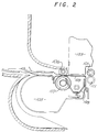
- is a diagram of the paper path within the inkjet printer of Fig 1;
- Fig 3
- is a block diagram of the main hardware components of an inkjet printer and the related software;
- Fig 4
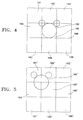
- shows how an image may be scanned by a non-overlap method.
- Fig 5
- shows how a difference may result in the method of Fig 4 if the same image is scanned by the same non-overlap method when the position of the image changes;
- Fig 6
- shows how scanning can be overlapped horizontally to reduce differences caused by positional variations of an image;
- Fig 7
- shows how scanning can be overlapped vertically to reduce differences caused by positional variations of an image;
- Fig 8
- is a flow chart showing the general steps performed by the printer in printing an image;
- Fig 9
- is a flow chart showing the steps performed by the printer for generating a density profile of an image to be printed;
- Fig 10
- is a flow chart showing the additional steps performed by the printer to find a grid with the maximum density in each row of grids;
- Fig 11
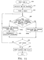
- is a flow chart showing the procedure performed in the printer to print a page;
- Fig 12
- is a flow chart showing the procedure performed in the printer to print a swath;
- Fig 13
- is a flow chart showing the steps performed in the printer for reducing its throughput to prevent smearing of the previous page;
- Fig 14
- is a flow chart showing the steps performed by the printer for determining the delay required to prevent smearing of the previous swath.
-
- Fig 1 is a diagram of an
inkjet printer 100 wherein the present invention is embodied. Theprinter 100 performs printing on sheets ofpaper 101 or other print media which are supplied from aninput tray 102. The print media are printed by a plurality ofinkjet nozzles 103 in theprinter 100. After a print medium is printed, it is output and stacked onto anoutput tray 104. - Fig 2 is a side view which shows the path along which a sheet of paper travels within the
printer 100. When a sheet of paper is picked fromtray 102, it is pushed by a feeder mechanism (not shown) into a paper path at the lower part of aforward paper guide 105. Before the paper passes inside the paper path defined byguide 105, it is preheated by heat generated from a preheater (not shown). - The paper path directs the paper to an interface between a
pinch wheel 106 and amain drive roller 107 which is rotated by a motor (not shown). Themain drive roller 107 and thepinch wheel 106 operate together to advance the paper over aplaten 109 which is heated by aheater 108. A swath of ink (typically 96 nozzles high, or about 8mm) is applied to the paper lying over the heated platen and theheater 108 accelerates the evaporation of solvent absorbed by the paper. - The
inkjet nozzles 103 are carried by a carriage which is driven along the support shaft by a mechanism which comprises, for example, a motor and a belt. Each trip along the support shaft is conventionally called a sweep. - The
inkjet nozzles 103, when activated, apply droplets of ink onto the paper. Typically, the inkjet nozzles are mounted on the carriage in a direction perpendicular to the direction of the sweep, so that columns of dots are printed in one sweep. The columns of dots made by inkjet nozzles across a horizontal portion of the paper is sometimes called a swath. A swath may be printed by one or more passes of the inkjet nozzles across the same horizontal portion, depending upon the required print mode. In order to reduce undesirable "banding", some of the known printing modes advance the print medium relative to the carriage in the vertical direction by only a fraction of the height of a single swath; in order to reduce "bleeding", multipass printing modes may be used in which the dots applied in successive passes are interleaved vertically and horizontally. Moreover, both single pass and multiple pass print modes may employ "Resolution Enhancement Technology" in which additional dots of ink are selectively applied between adjacent pixels to increase image density and/or to provide a smoother boundaries for curved or diagonal images. - When a swath is completely printed, the paper is advanced and ejected into the
output tray 104, with the assistance of starwheel 110 and an output roller 111 which cooperate to produce a pulling force on the paper. A starwheel is used so that its pointed edges can pull the paper at the printed surface without smearing. - Fig 3 is a logic diagram showing the main hardware components of the
printer 100 and the related software. The hardware components include acontroller 120 which operates to control the main operations of theprinter 100. For example, the controller controls the sheet feeding/stackingmechanism 121, including thepinch wheel 106, themain drive roller 107, the starwheel 110 and the output roller 111, to feed and position a sheet of paper during a printing process. Thecontroller 120 also controls thecarriage drive mechanism 122 to move the carriage across the paper. Thecontroller 120 also controls theinkjet nozzles 123 to activate them at appropriate times so that ink can be applied at the proper pixels of the paper. - The
controller 120 performs the control functions by executing instructions and data accessed from amemory 125. For example, data to be printed are received by theprinter 120 under the control of a software driver. The data received are stored in a "plot file" within adata area 126 in thememory 125. - The instructions can be classified logically into different procedures. These procedures include
different driver routines 127 such as a routine for controlling the motor which drives the main drive roller, a routine for controlling the motor which drives the output roller/star wheel, a routine for controlling the motor which drives the carriage and a routine for controlling activation of the inkjet nozzles. - One or
more timers 1 are available tocontroller 120. A timer may be simply be a starting clock value stored at a predetermined location in the memory. To obtain an elapsed time value, the stored starting value is then subtracted from an instantaneous clock value from a realtime clock (not shown). - The
memory 125 also stores athroughput procedure 129. The throughput procedure operates to control the throughput of theprinter 100. Throughput may be thought of as the sum of a first duration T1 and a second duration T2, where T1 is the time duration between the time immediately before a first swath is printed on a sheet of paper and the time immediately after the last swath is printed, and T2 is the time duration between the final position of one sheet and the initial position of the next sheet. T2 represents the sheet feeding delay of the printer, which is typically constrained only by the drive mechanism and is therefor a constant; however T1 is also constrained by various factors related to the complexity and density of the image and the desired print quality, which in turn determine how much time is required for each of the sequential process steps of the selected print mode.Throughput procedure 129 uses horizontal and vertical logic seeking to identify blank lines between adjacent swaths (vertical logic seeking) and blank portions at either end of (or possibly within) a swath, altogether avoiding any unnecessary carriage movements and slewing the carriage at maximum slew rate over any unprinted areas over which the carriage must be slewed. - The
memory 125 also stores adensitometer procedure 128 which determines a maximum density of dots of ink to be printed in the current swath, and a second pageanti-smear procedure 130 which operates in response to the results from thedensitometer procedure 128 to ensure that the ink of a preceding sheet of paper is not smeared when the current sheet of paper is output. - Typically, a sheet of paper is printed by applying ink at the specified dot positions (pixels). The dots may be printed in single (e.g., black) or multiple colors. To print a multiple color image, the carriage may have to make more than one sweep across the print medium and make two or more drops of ink with different primary colors at the same dot locations ("pixels"), as disclosed in U.S. Patent Number 4,855,752 which is assigned to the assignee of the present invention.
- The
printer 100 has several different modes of printing. Each of the different modes is used to produce a different type or quality of an image. For example, one or more "high quality" modes can be specified whereby density of the print dots is increased to enhance the quality of the printed images. In some printers, a "high quality" mode of printing may require theprinter 100 to make multiple passes across substantially the same horizontal portion of the page. - For example, in its high quality three pass mode,
printer 100 make three sweeps across the page to print a single swath. In each of the three sweeps, the printer would print one of every three consecutive dots so as to allow more time for one dot to dry before the neighboring dot is printed, and thereby preventing the possibility that the ink of the two neighboring dots would combine to produce an unwanted shape or color. Such a three pass printing mode may also be used to reduce banding by dividing the swath into three reduced-height bands, printed in successive but overlapping printing cycles each providing for three passes across an associated reduced-height band. - In known manner, the image to be printed is defined by the "plot file" which specified which pixels are and which pixels are not to be coated with dots of ink. For color images, the color of the ink is also specified in the plot file.
- Fig 8 is a flow chart showing the general steps performed by the printer in printing an image.
- To print a page, a plot file is first sent to the printer 100 (step 201). As the plot file is being received by the
printer 100, it is scanned by thecontroller 120. Thecontroller 120 scans the plot file to divide it into one or more printed swaths and at the same time produces a density profile for the entire page (step 201). - More particularly, when the
controller 120 scans the plot file, it also divides it into a plurality of grids each with a predetermined shape and size, each identified by an x-coordinate and a y-coordinate. For each grid, thecontroller 120 determines the number of dots that need to be printed with each type of ink. - According to one method, each swath to be printed in a single sweep of the carriage is subdivided into a plurality of rows and each row is subdivided into a plurality of non-overlapping grids; each dot on the page may belong to only one grid. The density of each grid is then determined by counting the number of pixels to be printed in a representative randomly selected sample of the pixels in the grid. A maximum row density is then obtained from the individual grid densities in each row, and a maximum sweep density is then obtained from the individual row densities in the sweep.
- Although such non-overlap scanning using only a representative sample is faster, it may, however, produce inaccurate results. To illustrate, assume an image to be printed by the printer has the
shape 160 as shown in Fig 4 and assume that the scanning is performed bysquare grids image 160 with respect to the grids, different density profiles may result. For example, if theimage 160 falls by chance in the middle of agrid 165 as shown in Fig 4 the density profile would show a high density, D1, ingrid 165. On the other hand, if same image 160' per chance falls in the intersection of grids 161', 162', 164' and 165' as shown in Fig. 5, then the highest density of the image 160' would be about a fourth of the density D1 obtain from the scanning performed as shown in Fig 4. - Moreover, accuracy of the local density profile is also a function of the size of the grid. For example, a density profile which is made with a non-overlapping grid size of 150x150 dots will more accurately reflect a dense image having a size of only 300x300 dots than a density profile which is made with a non-overlapping grid size of 300x300 dots. However, if grid size were so small that a single grid could have a density of 100% but the solvent could nevertheless rapidly diffuse into adjacent unprinted areas, such a small grid size would not provide a useful measure of the probability of an image being sufficiently dense to adversely affect print quality.
- However, more accurate measurement of the dot density may be obtained by overlapping the larger grids vertically and/or horizontally, to thereby obtain the advantages of both the larger and the smaller grid sizes. Fig 6 shows how horizontal overlapping is performed with respect to three exemplary grids G(1,1), G(1,2) and G(1,3). As shown, the left half of grid G(1,2) overlaps right half of grid G(1,1). On the other hand, the right half of grid G(1,2) is overlapped by the left half of grid G(1,3).
- Fig 7 shows how both vertical and horizontal overlapping may be combined. A first row of grids G(1,x), comprising grids G(1,1), G(1,2) and G(1,3) of Fig 6 and a second row G(2,x) of grids which overlap with the first row G(1,x). For example, the upper 5/6 of grid G(2,1) in the second row overlaps the lower 5/6 of grid G(1,1) of the first row, and the upper 5/6 of grid G(2,2) overlaps the lower 5/6 of grid G(1,2).
- Fig 9 is a flow chart illustrating the basic steps required to generate a density profile. The steps are performed by the densitometer procedure when it is executed by the
controller 120. - In
step 301, a grid of the image to be printed is scanned. In scanning the grid, each dot position of the grid is examined (step 302). Within the grid, the number of dot positions which will be printed with black dot and the number of dot positions which will be printed with colored dots are counted (step 303). Separate counts are made of black and colored dots because they are typically produced by inks having different formulations and concentrations. Because all the grids have the same size, the count can therefore be used directly to represent the density of the grip. After all the dot positions are examined, the count and the coordinates of the grid are stored into the memory 125 (step 304). Thecontroller 120 then examines the plot file to determine whether the current grid is the last grid of the page (step 305). If the current grid is not the last grid, then the process is repeated on the next grid (step 306). Otherwise, the procedure terminates. - In practice, rather than maintaining a density history for each grid, only a maximum density for one or more rows of grids is stored, with the size of the individual grids preferably being preferably decreased. As a row of grids is being scanned, the grid with the maximum density in the row is located, along with its density value. This is accomplished by providing a variable, GRID-ROW-MAX, and the additional steps shown in Fig 10 which are performed between
steps step 307, the count obtained fromstep 303 is compared with the value stored in GRID-ROW-MAX. If the count of the current grid is greater than GRID-ROW-MAX, its value is stored into GRID-ROW-MAX (step 308); otherwise,step 308 is bypassed. It will be understood that GRID-ROW-MAX is initialized (by setting it to "O") at the beginning of the procedure shown in Fig 9. If it is necessary to determine a maximum density for an area covering more than one grid row, this can be done by using a similar procedure to determine the maximum of the previously stored GRID-ROW-MAX values for each grid row involved. Alternatively, GRID-ROW-MAX is not re-initialized at the beginning of each row, but is re-initialized only once at the beginning of the area and is used until all the rows in that area have been processed. Similarly, if it is desired to determine a local density based on a grid size larger than that used to process the individual rows, this may be approximated by assuming that the maximum density locations in adjacent rows relate to adjacent portions of the image, and thus may be approximated by averaging the maximum densities of the adjoining rows; in any event, such an assumption would provide a calculated maximum density that is no less than the actual density. - Referring back to Fig 8, after the plot file is scanned and the required density information has been stored as a function of grid or row location, the page is printed (step 204). In practice, because only one swath is printed at a time, it is preferable to perform the printing operation (step 204) concurrently with the scanning operation (step 202), in which case as soon as all the pixels in one swath have been scanned, that swath can be printed, thereby increasing throughput and reducing the size of the buffer necessary to store the plot file.
- Fig 11 is a block diagram showing the procedure performed by the
controller 120 for printing a page N among a series of pages. - In
step 401 of the procedure, thecontroller 120 performs an initialization of theprinter 100 to print the page N. The initialization includes executing the appropriate driver routines to position the inkjet nozzles in a known position relative to a top corner of the page. When initialization is complete, thecontroller 120 causes the first swath of the page to be printed (step 402). - Before each swath is printed or skipped over in whole or in part by the throughput enhancement logic, the
controller 120 checks a page timer to see if the time elapsed since the printing of the last page, page N-1, has exceeded the throughput enhancement delay needed to avoid any possibility of smearing the previous page N-1 when page N is output (step 403). This delay is based upon the maximum density of page N-1. - As a first approximation, there is a linear relationship between the local density of a particular portion of the image and the required drying time before the ink in that portion is sufficiently dry that it will not be smeared when it comes into contact with another sheet. Accordingly, it is necessary to delay any contact of the particular portion of the first sheet with any part of the next sheet by a time:

where Tdry is the total drying time required, Kdry is an experimentally derived constant and Den is the density of the selected portion. - Although a separate Tdry could be calculated for each swath of the first page which would be used to start a timer as soon as that swath was printed, the required computations are simplified by determining only a single maximum density for the entire first page, and using that maximum density to calculate a worst case Tdry for that page. Since for equal ink density, the last portion to be printed will be the wettest, the implementation is further simplified by using only one timer and not starting the timer until the entire page has been printed.
- Consideration should also be given to the fact that in the preferred embodiment illustrated in Fig 1, as the next page is being printed, its leading edge (typically the top of the page) is propelled by the paper advance mechanism (starwheel 110 and output roller 111) away from the
platen 109 and into theoutput tray 104 in which the previously printed sheets are stacked, with the last printed sheet on the top of the stack with its printed side facing up. Thus, the leading edge of the page currently being printed is free to curve downward under the influence of gravity in the direction ofoutput tray 104 and first contacts the printed area of the previous sheet at a predetermined distance of about 9½'' (about 240mm) from the top. The leading edge of the next sheet then glides over the upper portion of the previous sheet until the current page has been printed and the two sheets are more or less aligned one on top of the other. Accordingly, the vertical location of the densely inked portion on the first page determines when it will first contacted by the next page. - It will also be appreciated that, in the absence of throughput enhancement strategies such as vertical and horizontal logic seeking, there is a fixed delay between the time page N is output into tray 24 and the time page N+1 will come into contact with page N. As a practical matter, it is advantageous to use that fixed delay to specify process variables such as ink drying time, in order to guarantee a minimum throughput rate for an entire page of graphics having at least some densely inked areas.
- Accordingly, the calculation of the required delay can be further simplified by realizing that rather than determine how much delay is required, it is sufficient to inhibit such throughput enhancement under certain degenerate conditions wherein a page having inked portions of higher than normal density is immediately followed by a page having relatively large printed areas.
- In an exemplary embodiment, these considerations are reflected in the following equation:

where
Inhibit is the elapsed time during which any throughput enhancement should be inhibited
K1 is an empirical offset constant
K2 is an empirical density coefficient
K3 is an empirical location coefficient
and
InhibitMax is predetermined maximum.
In the exemplary embodiment, InhibitMax is 48 seconds, (Den) ranges from 0 to 1 (1 being solid black) and (Loc) ranges linearly from 1 (at the top of the page) to 4 (at 240mm from the top); for all modes except high quality three pass mode, K1, K2 and K3 are zero (ie, there is no need to inhibit throughput enhancement). In the case of a high quality three pass mode (which prints a large black image with two drops of ink at every pixel), K1 is -15, K2 is 48 and K3 is 1. - Thus, in the exemplary embodiment, throughput enhancement in high quality three pass mode is inhibited for a maximum of 34 seconds for a 100% dense square at the top of the preceding page, for 33 seconds for the same square at the bottom of the page, or for 37 seconds for the same square at the more critical location 240mm from the top. If the density of the densest square is only 50%, the corresponding throughput enhancement delays are 11, 10 and 13 seconds, and for a 25% density are 0, 0 and 1 second.
- In
steps - If the time elapsed since the printing of page N-1 has not exceeded the delay required to prevent smearing of page N-1 when page N is output, then a throughput reduction procedure (step 405) is executed. On the other hand, if the elapsed time has exceeded the required delay, then the throughput reduction procedure is not executed.
- Referring back to Fig 11, in
step 406, thecontroller 120 checks whether the last swath of page N has been processed. If not, steps 403-406 are repeated. - If the last swath of page N has already been printed, then the elapsed time clock is restarted (step 407). The elapsed time clock is restarted so that it can be used in
step 403 when page N + 1 is being printed. - Fig 12 is a flow chart showing the procedure which the
controller 120 performs to print a swath. - Before printing or skipping over the next swath, the
controller 120 first determines the upper and lower boundaries of the previous swath (step 411). The upper boundary can be defined as the y-coordinate of the highest row of pixels in the swath and the lower boundary can be defined as the y-coordinate of the lowest row of pixels in the swath. - In
step 412, thecontroller 120 scans the density profile for all the grids (or the density profiles for all the rows, if only GRID-ROW-MAX was stored), whose y-coordinates are within the values of upper and lower boundaries of the previous swath and retrieves the maximum density associated with those grids (or rows), and stores its density in the memory 125 (step 413). To facilitate the concurrent scanning of the plot file and the printing of the individual swaths, a respective location can be reserved in thememory 125 for storing the value of the maximum density of each swath. Thecontroller 120 also checks to see if the maximum density of the previous swath is the highest density of the page (step 414). If so, the highest density of the page is then updated with the maximum density of the sweep (step 415). The value of the highest density of the page is used instep 403 of the procedure shown in Fig 11 for determined when the current page can be output without smearing the previous page. - The
controller 120 then determines whether a delay is required for the previous swath to dry so that it will not be smeared by the upcoming sweep. - The delay for preventing smearing of the previous swath can be determined by several methods.
- One such method is to perform a table look-up based upon the maximum density of the swath to find a minimum time delay for which the previous swath should remain over the
heated platen 109 before the paper is advanced or the carriage is moved over any portion of the previously printed swath, to thereby prevent any possibility of smearing. In order to speed up and simplify the required computations, separate tables are preferably maintained for different paper sizes and print modes; the table look-up is preferably performed using only the maximum density of the swath as determined in the densitometer procedure and preferably assumes a worst case condition that the maximum density is representative of average density over an area larger than a single grid. Thecontroller 120 performs the table look-up to determine the minimum time required for the swath. - The values of the table can be obtained empirically. Several sets of exemplary values are listed in the following tables:
A-size, Plain density Minimum Time (seconds) > 150 1.50 > 75 1.20 > 25 0.80 > 0 0.45 A-size, Color Transparency density Minimum Time (seconds) > 150 1.35 > 75 1.10 > 25 0.80 > 0 0.45 B-size, Plain, or Color Transparency density Minimum Time (seconds) > 150 1.70 > 75 1.40 > 25 0.90 > 0 0.45 - Another method for determining the delay, which is preferred for its greater accuracy, but which is computationally more complex, is illustrated in the flow chart of Fig 14. In
step 431, thecontroller 120 determines a delay factor (Sp) used to adjust the nominal advance delay (for each pass, if a multiple pass mode) of the current print mode based upon the swath's maximum density. This delay allows the solvent to evaporate sufficiently to prevent scraping of a previously printed swath while printing of the next swath. The swath density may include a value (Bden) which is the density of single color dots and a value (Cden) which is the density of multi-color dots obtained by the densitometer procedure. - In general, the delay factor (Sp) is determined by the formula:

where f(Mode, Bden, Cden) is a mode-dependent function of the density (Bden) of black dots and the density (Cden) of color dots on the swath. - In the preferred embodiment, the delay factor Sp is determined by the
formula 
where Sc, K1, K2 are empirically established coefficients, with only Sc and - Smin dependent on print mode. Exemplary values for K1 and K2 are 2.5 and .75 respectively. Exemplary values for Sc and Smin are set forth in the following Table:
Table Print Mode Sc Smin Normal 300 75 Performance 300 75 High-quality 1-pass 200 30 High-quality 3-pass 237 50 - To illustrate the application of the equation, assume that a page is printed in normal mode (i.e., the value of Sc is 300) and that the densest grid has 80% of its pixels printed with black dots. From the above, the preferred delay factor Sp is

- Thus, in normal and performance modes, a maximum black density of 80% or less will not cause any reduction of throughput. Similarly, a black density of 90% will cause a maximum reduction of throughput by reducing the nominal advance delay by the minimum delay factor of 75%; for density values between 80% and 90%, the advance delay will vary linearly between 100% and 75% of its nominal value.
- For
high quality 1 pass mode, the maximum slowdown (50%) is utilized for black densities greater than 68%, which increases linearly to 100% at a density of 40%. For the high quality 3 pass mode, the corresponding figures are 74.8% density (50% slowdown) and 54.8% density (no slowdown). - The
controller 120 then uses the delay factor Sp to determine the required advance delay (tp) for printing the swath upon the specified print mode of the swath (step 432). The time tp is determined in the preferred embodiment by dividing a nominal advance time tn by the delay factor Sp. The nominal advance time tn is dependent on the print mode and may be stored in a look-up table; in an exemplary embodiment, it is .527 seconds for a high quality three pass mode and .512 seconds for all other modes. - The result of the above identified division is then used to set a swatch delay timer. After the required advance delay time has elapsed (step 433), the
controller 120 activates the appropriate drivers to advance the print medium in preparation for the next sweep (step 416). When the delay has elapsed, thecontroller 120 then activates the appropriate drivers to cause the inkjet to make a sweep (step 417). After the sweep is made, thecontroller 120 checks to see if the sweep just made is the last sweep of the page (step 406). If the sweep is not the last one for the page, steps 411 to 418 are then repeated. - To summarize, in a preferred embodiment, a variable delay for preventing smearing of the swath just printed by contact with the nozzle plate or other parts of the printer mechanism is a function of the density profile of the swath, and a variable delay for preventing smearing of a previous page by contact with a next page is a function of the density profile of the previous page. These related concepts enable the printing of densely-inked images without smearing and without sacrificing throughput and print quality.
- It is understood that the above-described embodiment is merely provided to illustrate the principles of the present invention, and that other embodiments may readily be devised using these principles by those skilled in the art without departing from the scope and spirit of the invention.
Claims (10)
- A sheet fed inkjet printer (100) in which liquid ink is applied to a sheet of print medium (101) in a succession of horizontal swaths, comprising:
a print head having a plurality of vertically displaced print nozzles (103);
sheet feeding means (121) for advancing the sheet vertically past said print head;
carriage means (122) for slewing said print head horizontally across successive said horizontal swaths at respective vertically displaced portions of the sheet;
print means (123) for printing an image on said sheet by selectively applying dots of said ink to said sheet through selected ones of said nozzles as said print head is slewed by said carriage means;
throughput enhancement means (129) for varying an actual throughput rate determined by the sum of (a) a first elapsed time between the initial positioning of the print head adjacent a top portion of the sheet before the first horizontal swath has been printed and the final positioning of the print head at a bottom portion of the sheet after the last horizontal swath has been printed and (b) a sheet feeding delay equal to a second elapsed time between the final positioning of one sheet and the initial positioning of a next sheet;
densitometer means (128) responsive the respective locations of the dots for locating a densely printed area of said one sheet;
stacking means (121) for stacking successive said sheets after they have been printed; and anti-smear means (130) responsive to the densitometer means for causing the throughput means to maintain the actual throughout rate below a value where a next sheet is likely to come into contact with a densely printed area of a preceding sheet in the stacking means before the ink in said densely printed area of said preceding sheet has dried to a point where it is not subject to being smeared by such contact with said next sheet. - The printer of claim 1, wherein said densitometer means is responsive to said print means.
- The printer of claim 2, wherein said print means determines which pixels in a predetermined grid receive said dots of ink and said densitometer means counts the number of said dots in each said grid.
- The printer of claim 3, wherein said predetermined grid has substantially fewer rows and columns of pixels than are present in a single column of pixels in each of said horizontal swaths.
- The printer of claim 3, wherein said densitometer means utilizes overlapping said predetermined grids, with a horizontal overlap factor of at least 2 and a vertical overlap factor of at least 4.
- The printer of claim 1, wherein said throughput enhancement means searches for unprinted areas of each of said horizontal swaths.
- The printer of claim 6, wherein said throughput enhancement means searches for horizontal swaths having both printed and unprinted areas and causes the print head to horizontally traverse at least one of said unprinted areas at a higher slew rate.
- The printer of claim 6, wherein said throughput means searches for horizontal swaths having only unprinted areas, and causes the print head to continuously advance over successive such unprinted swaths.
- The printer of claim 6, wherein said throughput means reduces the number and/or size of said horizontal swaths.
- The printer of claim 6, wherein the anti-smear means determines a required delay before the head means is enabled by the throughput enhancement means to either traverse such unprinted areas at a higher slew rate, or skip such unprinted areas altogether.
Applications Claiming Priority (2)
| Application Number | Priority Date | Filing Date | Title |
|---|---|---|---|
| US56338 | 1993-04-30 | ||
| US08/056,338 US5489926A (en) | 1993-04-30 | 1993-04-30 | Adaptive control of second page printing to reduce smear in an inkjet printer |
Publications (3)
| Publication Number | Publication Date |
|---|---|
| EP0622204A2 true EP0622204A2 (en) | 1994-11-02 |
| EP0622204A3 EP0622204A3 (en) | 1995-05-17 |
| EP0622204B1 EP0622204B1 (en) | 1998-03-11 |
Family
ID=22003753
Family Applications (1)
| Application Number | Title | Priority Date | Filing Date |
|---|---|---|---|
| EP94302812A Expired - Lifetime EP0622204B1 (en) | 1993-04-30 | 1994-04-20 | Adaptive control of second page printing to reduce smear in an inkjet printer |
Country Status (4)
| Country | Link |
|---|---|
| US (1) | US5489926A (en) |
| EP (1) | EP0622204B1 (en) |
| JP (1) | JP3411664B2 (en) |
| DE (1) | DE69408890T2 (en) |
Cited By (2)
| Publication number | Priority date | Publication date | Assignee | Title |
|---|---|---|---|---|
| EP0720914A3 (en) * | 1995-01-03 | 1997-05-07 | Xerox Corp | Optimizing printing speed in an ink jet printer |
| EP1029687A1 (en) | 1999-02-18 | 2000-08-23 | Hewlett-Packard Company | Pixel-density augmentation and adjustment with minimum data, in an incremental printer |
Families Citing this family (16)
| Publication number | Priority date | Publication date | Assignee | Title |
|---|---|---|---|---|
| US5414453A (en) * | 1993-04-30 | 1995-05-09 | Hewlett-Packard Company | Use of a densitometer for adaptive control of printhead-to-media distance in ink jet printers |
| US5644683A (en) * | 1995-03-03 | 1997-07-01 | Hewlett-Packard Company | Print mode and system to alleviate wait-banding |
| US5949450A (en) * | 1996-03-15 | 1999-09-07 | Hewlett-Packard Company | Print mode and system to alleviate wait-banding |
| US6012792A (en) * | 1997-07-28 | 2000-01-11 | Hewlett-Packard Company | Copier having full color high speed inkjet printer with two intra page printing speeds for controlling ink drying time for images having densely inked areas |
| US5987229A (en) * | 1997-11-26 | 1999-11-16 | Lexmark International, Inc. | Method for controlling the passage of media through mixed speed print processes |
| US6145959A (en) * | 1997-12-22 | 2000-11-14 | Hewlett-Packard Company | Swath density control to improve print quality and extend printhead life in inkjet printers |
| DE60026252T2 (en) * | 1999-11-17 | 2006-08-17 | Canon K.K. | Pressure device and method for reducing the supply energy load for the pressure device |
| GB0001977D0 (en) * | 2000-01-29 | 2000-03-22 | Neopost Ltd | Control of use of ink cartridge |
| US6406119B1 (en) * | 2000-05-18 | 2002-06-18 | Samsung Electronics Co., Ltd. | Ink smearing preventing method of terminal equipment of inkjet output device |
| US6421581B1 (en) | 2000-09-12 | 2002-07-16 | Canon Kabushiki Kaisha | Printer with improved page feed |
| US6257784B1 (en) * | 2000-12-15 | 2001-07-10 | Xerox Corporation | Method for expediting the handling of printer bin output |
| CA2513435A1 (en) * | 2003-01-14 | 2004-08-05 | Tt Technologies, Inc. | Connection assembly for directional drilling |
| JP5219638B2 (en) * | 2008-06-06 | 2013-06-26 | キヤノン株式会社 | Inkjet recording device |
| US8755080B2 (en) | 2011-11-15 | 2014-06-17 | Eastman Kodak Company | Print content dependent adjustment of printed liquid |
| US9757955B2 (en) | 2015-12-09 | 2017-09-12 | Funai Electric Co., Ltd. | Imaging apparatus and method of using colorant density for reducing printing defects |
| US20210039408A1 (en) * | 2018-02-26 | 2021-02-11 | Hewlett-Packard Development Company, L.P. | Carriage delays for area fill regions |
Family Cites Families (11)
| Publication number | Priority date | Publication date | Assignee | Title |
|---|---|---|---|---|
| US4469026A (en) * | 1979-09-20 | 1984-09-04 | Ibm Corporation | Method and apparatus for controlling drying and detaching of printed material |
| JPS5769077A (en) * | 1980-10-16 | 1982-04-27 | Fuji Xerox Co Ltd | Control device for printer |
| US4566014A (en) * | 1984-05-31 | 1986-01-21 | The Mead Corporation | Drop counter printer control system |
| JPH01113249A (en) * | 1987-10-27 | 1989-05-01 | Canon Inc | Ink jet recording device |
| JP2745053B2 (en) * | 1988-09-14 | 1998-04-28 | キヤノン株式会社 | Recording device |
| EP0423820B1 (en) * | 1989-10-19 | 1996-01-31 | Seiko Epson Corporation | Ink jet printer |
| JPH03173647A (en) * | 1989-12-01 | 1991-07-26 | Seiko Epson Corp | Inkjet printer device |
| JP2861124B2 (en) * | 1989-10-19 | 1999-02-24 | セイコーエプソン株式会社 | Recording paper transport processing device for inkjet printer |
| JPH0439048A (en) * | 1990-06-05 | 1992-02-10 | Seiko Epson Corp | Ink jet printer |
| JP3109529B2 (en) * | 1991-02-06 | 2000-11-20 | セイコーエプソン株式会社 | Inkjet printer |
| US5214442A (en) * | 1991-09-27 | 1993-05-25 | Xerox Corporation | Adaptive dryer control for ink jet processors |
-
1993
- 1993-04-30 US US08/056,338 patent/US5489926A/en not_active Expired - Lifetime
-
1994
- 1994-04-20 DE DE69408890T patent/DE69408890T2/en not_active Expired - Fee Related
- 1994-04-20 EP EP94302812A patent/EP0622204B1/en not_active Expired - Lifetime
- 1994-04-26 JP JP08882494A patent/JP3411664B2/en not_active Expired - Fee Related
Cited By (3)
| Publication number | Priority date | Publication date | Assignee | Title |
|---|---|---|---|---|
| EP0720914A3 (en) * | 1995-01-03 | 1997-05-07 | Xerox Corp | Optimizing printing speed in an ink jet printer |
| US5714990A (en) * | 1995-01-03 | 1998-02-03 | Xerox Corporation | Optimizing printing speed and managing printed sheet ejection based on image density and method of determining density |
| EP1029687A1 (en) | 1999-02-18 | 2000-08-23 | Hewlett-Packard Company | Pixel-density augmentation and adjustment with minimum data, in an incremental printer |
Also Published As
| Publication number | Publication date |
|---|---|
| DE69408890D1 (en) | 1998-04-16 |
| US5489926A (en) | 1996-02-06 |
| DE69408890T2 (en) | 1998-06-25 |
| JPH0752378A (en) | 1995-02-28 |
| EP0622204A3 (en) | 1995-05-17 |
| JP3411664B2 (en) | 2003-06-03 |
| EP0622204B1 (en) | 1998-03-11 |
Similar Documents
| Publication | Publication Date | Title |
|---|---|---|
| EP0622203A2 (en) | Densitometer for adaptive control of ink drying time for inkjet printer | |
| EP0622204B1 (en) | Adaptive control of second page printing to reduce smear in an inkjet printer | |
| JP4336658B2 (en) | Print media edge print | |
| EP0771661B1 (en) | Use of a densitometer for adaptive control of printer heater output to optimize drying time for different print media | |
| EP0597714B1 (en) | Ink jet recording method and apparatus | |
| US6848765B1 (en) | End-of-page advance-distance decrease, in liquid-ink printers | |
| JPH08230178A (en) | Printing method by image density | |
| US6540315B1 (en) | Systems and methods for stitching overlapping swaths | |
| US20070291059A1 (en) | Inkjet recording apparatus and inkjet recording method | |
| US5870112A (en) | Dot scheduling for liquid ink printers | |
| JP4763886B2 (en) | Inkjet recording method and inkjet recording apparatus | |
| JP4164122B2 (en) | Method and apparatus for binding print band regions in an image forming apparatus | |
| US5619233A (en) | Bidirectional ink jet printing with head signature reduction | |
| US7506947B2 (en) | Ink jet printing apparatus and method using media shape detection | |
| US6712443B2 (en) | Ink jet recording apparatus and ink jet recording method | |
| EP0650846B1 (en) | Adaptive control of print head to medium distance in ink-jet printers | |
| EP0751476B1 (en) | Serial printer and printing method | |
| US20090033694A1 (en) | Printer control system and method for artifact free and borderless printing | |
| JPH1199638A (en) | Ink jet image recording method and apparatus | |
| JP2008023982A (en) | Inkjet recording apparatus and inkjet recording method | |
| US6312098B1 (en) | Banding reduction in incremental printing, through use of complementary weights for complementary printhead regions | |
| US6488356B1 (en) | Bidirectional color ink jet printing with head signature reduction | |
| JPH09193418A (en) | Ink jet recording device | |
| JP3293707B2 (en) | Ink jet recording device | |
| US6592197B2 (en) | Printer device and method |
Legal Events
| Date | Code | Title | Description |
|---|---|---|---|
| PUAI | Public reference made under article 153(3) epc to a published international application that has entered the european phase |
Free format text: ORIGINAL CODE: 0009012 |
|
| AK | Designated contracting states |
Kind code of ref document: A2 Designated state(s): DE FR GB IT |
|
| PUAL | Search report despatched |
Free format text: ORIGINAL CODE: 0009013 |
|
| AK | Designated contracting states |
Kind code of ref document: A3 Designated state(s): DE FR GB IT |
|
| 17P | Request for examination filed |
Effective date: 19950928 |
|
| 17Q | First examination report despatched |
Effective date: 19960918 |
|
| GRAG | Despatch of communication of intention to grant |
Free format text: ORIGINAL CODE: EPIDOS AGRA |
|
| GRAG | Despatch of communication of intention to grant |
Free format text: ORIGINAL CODE: EPIDOS AGRA |
|
| GRAG | Despatch of communication of intention to grant |
Free format text: ORIGINAL CODE: EPIDOS AGRA |
|
| GRAH | Despatch of communication of intention to grant a patent |
Free format text: ORIGINAL CODE: EPIDOS IGRA |
|
| GRAH | Despatch of communication of intention to grant a patent |
Free format text: ORIGINAL CODE: EPIDOS IGRA |
|
| GRAA | (expected) grant |
Free format text: ORIGINAL CODE: 0009210 |
|
| AK | Designated contracting states |
Kind code of ref document: B1 Designated state(s): DE FR GB IT |
|
| ITF | It: translation for a ep patent filed | ||
| REF | Corresponds to: |
Ref document number: 69408890 Country of ref document: DE Date of ref document: 19980416 |
|
| ET | Fr: translation filed | ||
| PLBE | No opposition filed within time limit |
Free format text: ORIGINAL CODE: 0009261 |
|
| STAA | Information on the status of an ep patent application or granted ep patent |
Free format text: STATUS: NO OPPOSITION FILED WITHIN TIME LIMIT |
|
| 26N | No opposition filed | ||
| REG | Reference to a national code |
Ref country code: GB Ref legal event code: 732E |
|
| REG | Reference to a national code |
Ref country code: FR Ref legal event code: TP |
|
| REG | Reference to a national code |
Ref country code: GB Ref legal event code: IF02 |
|
| PGFP | Annual fee paid to national office [announced via postgrant information from national office to epo] |
Ref country code: IT Payment date: 20060430 Year of fee payment: 13 |
|
| PGFP | Annual fee paid to national office [announced via postgrant information from national office to epo] |
Ref country code: DE Payment date: 20070531 Year of fee payment: 14 |
|
| PGFP | Annual fee paid to national office [announced via postgrant information from national office to epo] |
Ref country code: GB Payment date: 20070425 Year of fee payment: 14 |
|
| PGFP | Annual fee paid to national office [announced via postgrant information from national office to epo] |
Ref country code: FR Payment date: 20070417 Year of fee payment: 14 |
|
| GBPC | Gb: european patent ceased through non-payment of renewal fee |
Effective date: 20080420 |
|
| PG25 | Lapsed in a contracting state [announced via postgrant information from national office to epo] |
Ref country code: DE Free format text: LAPSE BECAUSE OF NON-PAYMENT OF DUE FEES Effective date: 20081101 |
|
| REG | Reference to a national code |
Ref country code: FR Ref legal event code: ST Effective date: 20081231 |
|
| PG25 | Lapsed in a contracting state [announced via postgrant information from national office to epo] |
Ref country code: FR Free format text: LAPSE BECAUSE OF NON-PAYMENT OF DUE FEES Effective date: 20080430 |
|
| PG25 | Lapsed in a contracting state [announced via postgrant information from national office to epo] |
Ref country code: GB Free format text: LAPSE BECAUSE OF NON-PAYMENT OF DUE FEES Effective date: 20080420 |
|
| PG25 | Lapsed in a contracting state [announced via postgrant information from national office to epo] |
Ref country code: IT Free format text: LAPSE BECAUSE OF NON-PAYMENT OF DUE FEES Effective date: 20070420 |