EP0622061B1 - Femoral component for a hip prothesis - Google Patents
Femoral component for a hip prothesis Download PDFInfo
- Publication number
- EP0622061B1 EP0622061B1 EP94106778A EP94106778A EP0622061B1 EP 0622061 B1 EP0622061 B1 EP 0622061B1 EP 94106778 A EP94106778 A EP 94106778A EP 94106778 A EP94106778 A EP 94106778A EP 0622061 B1 EP0622061 B1 EP 0622061B1
- Authority
- EP
- European Patent Office
- Prior art keywords
- femoral component
- cross
- section
- proximal
- circular arc
- Prior art date
- Legal status (The legal status is an assumption and is not a legal conclusion. Google has not performed a legal analysis and makes no representation as to the accuracy of the status listed.)
- Expired - Lifetime
Links
- 210000000689 upper leg Anatomy 0.000 claims description 21
- 238000002513 implantation Methods 0.000 claims description 3
- 210000001624 hip Anatomy 0.000 description 14
- 210000000988 bone and bone Anatomy 0.000 description 11
- 239000007943 implant Substances 0.000 description 11
- 238000000034 method Methods 0.000 description 5
- 210000004394 hip joint Anatomy 0.000 description 4
- 238000013461 design Methods 0.000 description 3
- 238000002360 preparation method Methods 0.000 description 3
- 238000001356 surgical procedure Methods 0.000 description 3
- 238000012546 transfer Methods 0.000 description 3
- 210000000588 acetabulum Anatomy 0.000 description 2
- 210000003484 anatomy Anatomy 0.000 description 2
- 238000011882 arthroplasty Methods 0.000 description 2
- 238000011960 computer-aided design Methods 0.000 description 2
- 238000002156 mixing Methods 0.000 description 2
- 230000007704 transition Effects 0.000 description 2
- 208000006820 Arthralgia Diseases 0.000 description 1
- 208000002193 Pain Diseases 0.000 description 1
- 230000001154 acute effect Effects 0.000 description 1
- 210000000577 adipose tissue Anatomy 0.000 description 1
- 238000013459 approach Methods 0.000 description 1
- 206010003246 arthritis Diseases 0.000 description 1
- 239000004568 cement Substances 0.000 description 1
- 230000001054 cortical effect Effects 0.000 description 1
- 230000002708 enhancing effect Effects 0.000 description 1
- 210000000527 greater trochanter Anatomy 0.000 description 1
- 239000000203 mixture Substances 0.000 description 1
- NJPPVKZQTLUDBO-UHFFFAOYSA-N novaluron Chemical compound C1=C(Cl)C(OC(F)(F)C(OC(F)(F)F)F)=CC=C1NC(=O)NC(=O)C1=C(F)C=CC=C1F NJPPVKZQTLUDBO-UHFFFAOYSA-N 0.000 description 1
- 229920003229 poly(methyl methacrylate) Polymers 0.000 description 1
- 239000004926 polymethyl methacrylate Substances 0.000 description 1
- 238000004321 preservation Methods 0.000 description 1
Images


Classifications
-
- A—HUMAN NECESSITIES
- A61—MEDICAL OR VETERINARY SCIENCE; HYGIENE
- A61F—FILTERS IMPLANTABLE INTO BLOOD VESSELS; PROSTHESES; DEVICES PROVIDING PATENCY TO, OR PREVENTING COLLAPSING OF, TUBULAR STRUCTURES OF THE BODY, e.g. STENTS; ORTHOPAEDIC, NURSING OR CONTRACEPTIVE DEVICES; FOMENTATION; TREATMENT OR PROTECTION OF EYES OR EARS; BANDAGES, DRESSINGS OR ABSORBENT PADS; FIRST-AID KITS
- A61F2/00—Filters implantable into blood vessels; Prostheses, i.e. artificial substitutes or replacements for parts of the body; Appliances for connecting them with the body; Devices providing patency to, or preventing collapsing of, tubular structures of the body, e.g. stents
- A61F2/02—Prostheses implantable into the body
- A61F2/30—Joints
- A61F2/32—Joints for the hip
- A61F2/36—Femoral heads ; Femoral endoprostheses
- A61F2/3662—Femoral shafts
-
- A—HUMAN NECESSITIES
- A61—MEDICAL OR VETERINARY SCIENCE; HYGIENE
- A61B—DIAGNOSIS; SURGERY; IDENTIFICATION
- A61B17/00—Surgical instruments, devices or methods, e.g. tourniquets
- A61B17/16—Bone cutting, breaking or removal means other than saws, e.g. Osteoclasts; Drills or chisels for bones; Trepans
- A61B17/17—Guides or aligning means for drills, mills, pins or wires
- A61B17/1739—Guides or aligning means for drills, mills, pins or wires specially adapted for particular parts of the body
- A61B17/1742—Guides or aligning means for drills, mills, pins or wires specially adapted for particular parts of the body for the hip
- A61B17/175—Guides or aligning means for drills, mills, pins or wires specially adapted for particular parts of the body for the hip for preparing the femur for hip prosthesis insertion
-
- A—HUMAN NECESSITIES
- A61—MEDICAL OR VETERINARY SCIENCE; HYGIENE
- A61F—FILTERS IMPLANTABLE INTO BLOOD VESSELS; PROSTHESES; DEVICES PROVIDING PATENCY TO, OR PREVENTING COLLAPSING OF, TUBULAR STRUCTURES OF THE BODY, e.g. STENTS; ORTHOPAEDIC, NURSING OR CONTRACEPTIVE DEVICES; FOMENTATION; TREATMENT OR PROTECTION OF EYES OR EARS; BANDAGES, DRESSINGS OR ABSORBENT PADS; FIRST-AID KITS
- A61F2/00—Filters implantable into blood vessels; Prostheses, i.e. artificial substitutes or replacements for parts of the body; Appliances for connecting them with the body; Devices providing patency to, or preventing collapsing of, tubular structures of the body, e.g. stents
- A61F2/02—Prostheses implantable into the body
- A61F2/30—Joints
- A61F2/3094—Designing or manufacturing processes
- A61F2/30942—Designing or manufacturing processes for designing or making customized prostheses, e.g. using templates, CT or NMR scans, finite-element analysis or CAD-CAM techniques
-
- A—HUMAN NECESSITIES
- A61—MEDICAL OR VETERINARY SCIENCE; HYGIENE
- A61B—DIAGNOSIS; SURGERY; IDENTIFICATION
- A61B17/00—Surgical instruments, devices or methods, e.g. tourniquets
- A61B17/16—Bone cutting, breaking or removal means other than saws, e.g. Osteoclasts; Drills or chisels for bones; Trepans
- A61B17/1659—Surgical rasps, files, planes, or scrapers
-
- A—HUMAN NECESSITIES
- A61—MEDICAL OR VETERINARY SCIENCE; HYGIENE
- A61F—FILTERS IMPLANTABLE INTO BLOOD VESSELS; PROSTHESES; DEVICES PROVIDING PATENCY TO, OR PREVENTING COLLAPSING OF, TUBULAR STRUCTURES OF THE BODY, e.g. STENTS; ORTHOPAEDIC, NURSING OR CONTRACEPTIVE DEVICES; FOMENTATION; TREATMENT OR PROTECTION OF EYES OR EARS; BANDAGES, DRESSINGS OR ABSORBENT PADS; FIRST-AID KITS
- A61F2/00—Filters implantable into blood vessels; Prostheses, i.e. artificial substitutes or replacements for parts of the body; Appliances for connecting them with the body; Devices providing patency to, or preventing collapsing of, tubular structures of the body, e.g. stents
- A61F2/02—Prostheses implantable into the body
- A61F2/30—Joints
- A61F2/32—Joints for the hip
- A61F2/36—Femoral heads ; Femoral endoprostheses
- A61F2/3662—Femoral shafts
- A61F2/367—Proximal or metaphyseal parts of shafts
-
- A—HUMAN NECESSITIES
- A61—MEDICAL OR VETERINARY SCIENCE; HYGIENE
- A61F—FILTERS IMPLANTABLE INTO BLOOD VESSELS; PROSTHESES; DEVICES PROVIDING PATENCY TO, OR PREVENTING COLLAPSING OF, TUBULAR STRUCTURES OF THE BODY, e.g. STENTS; ORTHOPAEDIC, NURSING OR CONTRACEPTIVE DEVICES; FOMENTATION; TREATMENT OR PROTECTION OF EYES OR EARS; BANDAGES, DRESSINGS OR ABSORBENT PADS; FIRST-AID KITS
- A61F2/00—Filters implantable into blood vessels; Prostheses, i.e. artificial substitutes or replacements for parts of the body; Appliances for connecting them with the body; Devices providing patency to, or preventing collapsing of, tubular structures of the body, e.g. stents
- A61F2/02—Prostheses implantable into the body
- A61F2/30—Joints
- A61F2/32—Joints for the hip
- A61F2/36—Femoral heads ; Femoral endoprostheses
- A61F2/3662—Femoral shafts
- A61F2/3672—Intermediate parts of shafts
-
- A—HUMAN NECESSITIES
- A61—MEDICAL OR VETERINARY SCIENCE; HYGIENE
- A61F—FILTERS IMPLANTABLE INTO BLOOD VESSELS; PROSTHESES; DEVICES PROVIDING PATENCY TO, OR PREVENTING COLLAPSING OF, TUBULAR STRUCTURES OF THE BODY, e.g. STENTS; ORTHOPAEDIC, NURSING OR CONTRACEPTIVE DEVICES; FOMENTATION; TREATMENT OR PROTECTION OF EYES OR EARS; BANDAGES, DRESSINGS OR ABSORBENT PADS; FIRST-AID KITS
- A61F2/00—Filters implantable into blood vessels; Prostheses, i.e. artificial substitutes or replacements for parts of the body; Appliances for connecting them with the body; Devices providing patency to, or preventing collapsing of, tubular structures of the body, e.g. stents
- A61F2/02—Prostheses implantable into the body
- A61F2/30—Joints
- A61F2/32—Joints for the hip
- A61F2/36—Femoral heads ; Femoral endoprostheses
- A61F2/3662—Femoral shafts
- A61F2/3676—Distal or diaphyseal parts of shafts
-
- A—HUMAN NECESSITIES
- A61—MEDICAL OR VETERINARY SCIENCE; HYGIENE
- A61F—FILTERS IMPLANTABLE INTO BLOOD VESSELS; PROSTHESES; DEVICES PROVIDING PATENCY TO, OR PREVENTING COLLAPSING OF, TUBULAR STRUCTURES OF THE BODY, e.g. STENTS; ORTHOPAEDIC, NURSING OR CONTRACEPTIVE DEVICES; FOMENTATION; TREATMENT OR PROTECTION OF EYES OR EARS; BANDAGES, DRESSINGS OR ABSORBENT PADS; FIRST-AID KITS
- A61F2/00—Filters implantable into blood vessels; Prostheses, i.e. artificial substitutes or replacements for parts of the body; Appliances for connecting them with the body; Devices providing patency to, or preventing collapsing of, tubular structures of the body, e.g. stents
- A61F2/02—Prostheses implantable into the body
- A61F2/30—Joints
- A61F2002/30001—Additional features of subject-matter classified in A61F2/28, A61F2/30 and subgroups thereof
- A61F2002/30108—Shapes
- A61F2002/3011—Cross-sections or two-dimensional shapes
- A61F2002/30112—Rounded shapes, e.g. with rounded corners
- A61F2002/30113—Rounded shapes, e.g. with rounded corners circular
-
- A—HUMAN NECESSITIES
- A61—MEDICAL OR VETERINARY SCIENCE; HYGIENE
- A61F—FILTERS IMPLANTABLE INTO BLOOD VESSELS; PROSTHESES; DEVICES PROVIDING PATENCY TO, OR PREVENTING COLLAPSING OF, TUBULAR STRUCTURES OF THE BODY, e.g. STENTS; ORTHOPAEDIC, NURSING OR CONTRACEPTIVE DEVICES; FOMENTATION; TREATMENT OR PROTECTION OF EYES OR EARS; BANDAGES, DRESSINGS OR ABSORBENT PADS; FIRST-AID KITS
- A61F2/00—Filters implantable into blood vessels; Prostheses, i.e. artificial substitutes or replacements for parts of the body; Appliances for connecting them with the body; Devices providing patency to, or preventing collapsing of, tubular structures of the body, e.g. stents
- A61F2/02—Prostheses implantable into the body
- A61F2/30—Joints
- A61F2002/30001—Additional features of subject-matter classified in A61F2/28, A61F2/30 and subgroups thereof
- A61F2002/30108—Shapes
- A61F2002/3011—Cross-sections or two-dimensional shapes
- A61F2002/30138—Convex polygonal shapes
-
- A—HUMAN NECESSITIES
- A61—MEDICAL OR VETERINARY SCIENCE; HYGIENE
- A61F—FILTERS IMPLANTABLE INTO BLOOD VESSELS; PROSTHESES; DEVICES PROVIDING PATENCY TO, OR PREVENTING COLLAPSING OF, TUBULAR STRUCTURES OF THE BODY, e.g. STENTS; ORTHOPAEDIC, NURSING OR CONTRACEPTIVE DEVICES; FOMENTATION; TREATMENT OR PROTECTION OF EYES OR EARS; BANDAGES, DRESSINGS OR ABSORBENT PADS; FIRST-AID KITS
- A61F2/00—Filters implantable into blood vessels; Prostheses, i.e. artificial substitutes or replacements for parts of the body; Appliances for connecting them with the body; Devices providing patency to, or preventing collapsing of, tubular structures of the body, e.g. stents
- A61F2/02—Prostheses implantable into the body
- A61F2/30—Joints
- A61F2002/30001—Additional features of subject-matter classified in A61F2/28, A61F2/30 and subgroups thereof
- A61F2002/30108—Shapes
- A61F2002/30199—Three-dimensional shapes
- A61F2002/30205—Three-dimensional shapes conical
-
- A—HUMAN NECESSITIES
- A61—MEDICAL OR VETERINARY SCIENCE; HYGIENE
- A61F—FILTERS IMPLANTABLE INTO BLOOD VESSELS; PROSTHESES; DEVICES PROVIDING PATENCY TO, OR PREVENTING COLLAPSING OF, TUBULAR STRUCTURES OF THE BODY, e.g. STENTS; ORTHOPAEDIC, NURSING OR CONTRACEPTIVE DEVICES; FOMENTATION; TREATMENT OR PROTECTION OF EYES OR EARS; BANDAGES, DRESSINGS OR ABSORBENT PADS; FIRST-AID KITS
- A61F2/00—Filters implantable into blood vessels; Prostheses, i.e. artificial substitutes or replacements for parts of the body; Appliances for connecting them with the body; Devices providing patency to, or preventing collapsing of, tubular structures of the body, e.g. stents
- A61F2/02—Prostheses implantable into the body
- A61F2/30—Joints
- A61F2/3094—Designing or manufacturing processes
- A61F2/30942—Designing or manufacturing processes for designing or making customized prostheses, e.g. using templates, CT or NMR scans, finite-element analysis or CAD-CAM techniques
- A61F2002/30943—Designing or manufacturing processes for designing or making customized prostheses, e.g. using templates, CT or NMR scans, finite-element analysis or CAD-CAM techniques using mathematical models
-
- A—HUMAN NECESSITIES
- A61—MEDICAL OR VETERINARY SCIENCE; HYGIENE
- A61F—FILTERS IMPLANTABLE INTO BLOOD VESSELS; PROSTHESES; DEVICES PROVIDING PATENCY TO, OR PREVENTING COLLAPSING OF, TUBULAR STRUCTURES OF THE BODY, e.g. STENTS; ORTHOPAEDIC, NURSING OR CONTRACEPTIVE DEVICES; FOMENTATION; TREATMENT OR PROTECTION OF EYES OR EARS; BANDAGES, DRESSINGS OR ABSORBENT PADS; FIRST-AID KITS
- A61F2/00—Filters implantable into blood vessels; Prostheses, i.e. artificial substitutes or replacements for parts of the body; Appliances for connecting them with the body; Devices providing patency to, or preventing collapsing of, tubular structures of the body, e.g. stents
- A61F2/02—Prostheses implantable into the body
- A61F2/30—Joints
- A61F2/3094—Designing or manufacturing processes
- A61F2/30942—Designing or manufacturing processes for designing or making customized prostheses, e.g. using templates, CT or NMR scans, finite-element analysis or CAD-CAM techniques
- A61F2002/30952—Designing or manufacturing processes for designing or making customized prostheses, e.g. using templates, CT or NMR scans, finite-element analysis or CAD-CAM techniques using CAD-CAM techniques or NC-techniques
-
- A—HUMAN NECESSITIES
- A61—MEDICAL OR VETERINARY SCIENCE; HYGIENE
- A61F—FILTERS IMPLANTABLE INTO BLOOD VESSELS; PROSTHESES; DEVICES PROVIDING PATENCY TO, OR PREVENTING COLLAPSING OF, TUBULAR STRUCTURES OF THE BODY, e.g. STENTS; ORTHOPAEDIC, NURSING OR CONTRACEPTIVE DEVICES; FOMENTATION; TREATMENT OR PROTECTION OF EYES OR EARS; BANDAGES, DRESSINGS OR ABSORBENT PADS; FIRST-AID KITS
- A61F2/00—Filters implantable into blood vessels; Prostheses, i.e. artificial substitutes or replacements for parts of the body; Appliances for connecting them with the body; Devices providing patency to, or preventing collapsing of, tubular structures of the body, e.g. stents
- A61F2/02—Prostheses implantable into the body
- A61F2/30—Joints
- A61F2/32—Joints for the hip
- A61F2/36—Femoral heads ; Femoral endoprostheses
- A61F2/3609—Femoral heads or necks; Connections of endoprosthetic heads or necks to endoprosthetic femoral shafts
- A61F2002/3625—Necks
-
- A—HUMAN NECESSITIES
- A61—MEDICAL OR VETERINARY SCIENCE; HYGIENE
- A61F—FILTERS IMPLANTABLE INTO BLOOD VESSELS; PROSTHESES; DEVICES PROVIDING PATENCY TO, OR PREVENTING COLLAPSING OF, TUBULAR STRUCTURES OF THE BODY, e.g. STENTS; ORTHOPAEDIC, NURSING OR CONTRACEPTIVE DEVICES; FOMENTATION; TREATMENT OR PROTECTION OF EYES OR EARS; BANDAGES, DRESSINGS OR ABSORBENT PADS; FIRST-AID KITS
- A61F2/00—Filters implantable into blood vessels; Prostheses, i.e. artificial substitutes or replacements for parts of the body; Appliances for connecting them with the body; Devices providing patency to, or preventing collapsing of, tubular structures of the body, e.g. stents
- A61F2/02—Prostheses implantable into the body
- A61F2/30—Joints
- A61F2/32—Joints for the hip
- A61F2/36—Femoral heads ; Femoral endoprostheses
- A61F2/3609—Femoral heads or necks; Connections of endoprosthetic heads or necks to endoprosthetic femoral shafts
- A61F2002/365—Connections of heads to necks
-
- A—HUMAN NECESSITIES
- A61—MEDICAL OR VETERINARY SCIENCE; HYGIENE
- A61F—FILTERS IMPLANTABLE INTO BLOOD VESSELS; PROSTHESES; DEVICES PROVIDING PATENCY TO, OR PREVENTING COLLAPSING OF, TUBULAR STRUCTURES OF THE BODY, e.g. STENTS; ORTHOPAEDIC, NURSING OR CONTRACEPTIVE DEVICES; FOMENTATION; TREATMENT OR PROTECTION OF EYES OR EARS; BANDAGES, DRESSINGS OR ABSORBENT PADS; FIRST-AID KITS
- A61F2230/00—Geometry of prostheses classified in groups A61F2/00 - A61F2/26 or A61F2/82 or A61F9/00 or A61F11/00 or subgroups thereof
- A61F2230/0002—Two-dimensional shapes, e.g. cross-sections
- A61F2230/0004—Rounded shapes, e.g. with rounded corners
- A61F2230/0006—Rounded shapes, e.g. with rounded corners circular
-
- A—HUMAN NECESSITIES
- A61—MEDICAL OR VETERINARY SCIENCE; HYGIENE
- A61F—FILTERS IMPLANTABLE INTO BLOOD VESSELS; PROSTHESES; DEVICES PROVIDING PATENCY TO, OR PREVENTING COLLAPSING OF, TUBULAR STRUCTURES OF THE BODY, e.g. STENTS; ORTHOPAEDIC, NURSING OR CONTRACEPTIVE DEVICES; FOMENTATION; TREATMENT OR PROTECTION OF EYES OR EARS; BANDAGES, DRESSINGS OR ABSORBENT PADS; FIRST-AID KITS
- A61F2230/00—Geometry of prostheses classified in groups A61F2/00 - A61F2/26 or A61F2/82 or A61F9/00 or A61F11/00 or subgroups thereof
- A61F2230/0002—Two-dimensional shapes, e.g. cross-sections
- A61F2230/0017—Angular shapes
-
- A—HUMAN NECESSITIES
- A61—MEDICAL OR VETERINARY SCIENCE; HYGIENE
- A61F—FILTERS IMPLANTABLE INTO BLOOD VESSELS; PROSTHESES; DEVICES PROVIDING PATENCY TO, OR PREVENTING COLLAPSING OF, TUBULAR STRUCTURES OF THE BODY, e.g. STENTS; ORTHOPAEDIC, NURSING OR CONTRACEPTIVE DEVICES; FOMENTATION; TREATMENT OR PROTECTION OF EYES OR EARS; BANDAGES, DRESSINGS OR ABSORBENT PADS; FIRST-AID KITS
- A61F2230/00—Geometry of prostheses classified in groups A61F2/00 - A61F2/26 or A61F2/82 or A61F9/00 or A61F11/00 or subgroups thereof
- A61F2230/0063—Three-dimensional shapes
- A61F2230/0067—Three-dimensional shapes conical
Definitions
- the present invention relates to a femoral component for a hip prosthesis to be used in total hip arthroplasty. More specifically, it relates to a femoral component having a shape which provides a better fit with the femoral medullary canal.
- a ball on the proximal end of the stem cooperates with a prosthetic socket implanted in a prepared natural acetabulum and thereby provides for articulation between the femur and the acetabulum after the femoral head has been resected and the proximal femur cleared of cancellous bone proximally and fatty tissue distally.
- fixation be attained between the stem and healthy bone bed.
- a polymethylmethacrylate cement can act as a bone between the implant and the interstices of the prepared bone bed.
- press fit relies on the dimensional difference between the implant and prepared bone bed for stability.
- a third fixation method provides a 3-dimensional texture on the implant's surface that, when used in a "line to line” or slightly undersized prepared bone bed, allows for bony ingrowth texture.
- U.S. Patent 4,589,883 teaches a proximal portion which is elliptical in cross-section with its major and minor axes twisted along the proximal direction.
- U.S. Patent 4,589,883 teaches a proximal portion which is elliptical in cross-section with its major and minor axes twisted along the proximal direction.
- Patent 4,435,854 (now Reissue Patent 32,471) relates to a hip joint prosthesis having a stem which, in its proximal region, has a curvature in the anterior-posterior plane with a center of curvature anteriorly and, in its distal region, includes a shank having a curvature in the opposite direction in the anterior-posterior plane, i.e. at its center of curvature posteriorly.
- This design supposedly reduces the tendency of the shank to turn within the medullary canal.
- U.S. Patent 5,002,580 relates to a femoral component designed to provide a non-uniform interference press fit with the intramedullary canal. With this design, the femoral canal is prepared in such a manner that the prosthesis has line-to-line contact with cortical bone on the lateral side and produces an interference fit with the softer cancellous bone on the medal side of the femur.
- U.S. Patent 4,813,983 relates to a femoral component for a hip prosthesis including a proximal portion with an asymmetric contour defining an anterior side which forms an acute angle with a lateral side and the posterior side approaches the anterior side in a direction of the medal side. Furthermore, the medial side is arcuate in shape while the other sides include linear edges in cross-section.
- WO-A-9408534 pertains to a femur pin of a hip-joint endoprosthesis wherein the cross-section of the femur pin twists from proximal to distal in such a way that the transverse-oval cross-section in the proximal region turns to a sagittal-oval cross-section in the distal region.
- a femoral prosthesis can be broadly characterized as also having straight or curved stems.
- Straight prostheses are left/right interchangeable and are less technically demanding to implant than curved stem prostheses.
- curved stem prostheses while being somewhat more demanding for the surgeon to implant, provide the advantage of an improved fit within the prepared femoral canal.
- the design of the present invention possesses a unique geometry which provides the superior proximal fit afforded by a curved stem prosthesis, but can utilize the proven canal preparation techniques employed in the implantation of straight stem prostheses.
- the prostheses of the present invention can be broken into three regions and can be described geometrically as a distal parabolic section, a conical mid-stem section and a proximal geometry which medially and anteriorly conforms to the anatomy of a natural femoral medullary canal, and posteriorly and laterally fills the space created by a guided chisel used to groove the trochanteric bed.
- the improved proximal fit is accomplished in the present invention by having a direct relationship between the prosthesis shape and the shape of the instruments used to prepare the femur.
- This relationship uses known mathematical techniques to generate surfaces of the proximal prosthesis from the chisel profile and sectional radii of the reamer. This allows the surgeon to prepare the proximal femur knowing that he will have excellent proximal fit, especially posteriorly and laterally.
- a femoral component for a hip prosthesis which has a distal portion defining a central longitudinal axis.
- the femoral component has a proximal portion shaped in a manner wherein a cross-section taken perpendicular to the central axis has a medial, posterior, lateral and anterior side.
- the medial side is formed as a first circular arc having a center located within the cross-section.
- the comer of the cross-section formed by the posterior and lateral sides is formed as a second circular arc with a center on the central axis.
- the anterior side is substantially arcuate and convex in form and is tangent to the first circular arc at the point of intersection therewith.
- the posterior side is also substantially arcuate, but concave in form and is tangent to both the first and second circular arcs.
- a generally arcuate portion connects the second circular arc with the anterior side, the connection being made at connecting points on the second circular arc and the anterior side such that the arcuate portion forms a tangent with the second circular arc and the anterior side at the connection point.
- the substantially arcuate anterior side of each cross-section of the proximal portion is an arc of a circle having its center on a line extending through the center of said second circular arc, which line is also perpendicular to a line containing the central axis on both the centers of said first and second circular arcs.
- the radii of the arcs is related to the radii of the reamer which will be used by the surgeon to prepare the canal.
- each cross-section is an arc of a circle having its center on a line extending through the center of the first circular arc and perpendicular to the plane containing the central axis and the centers of the first and second circular arcs.
- the lateral side of the femoral component in the proximal area diverges away from the central axis on moving from proximal to distal parallel to the central axis.
- the prosthesis 10 can be broken into a distal region 12, a mid-stem region 14 and a proximal region 16.
- Distal region 12 can be described geometrically as distal parabolic section
- mid-stem region 14 and the proximal generally conical region 16 conform medially and anteriorly to the anatomy, and posteriorly and laterally fills the space created by a shaped chisel (not shown).
- a central axis 18 extends through prosthesis 10 and generally coincides with the axis of the proximal femur.
- Prosthesis 10 is provided with lateral flare F at the juncture of the proximal portion 16 and section 14, allowing for additional stress transfer to the cortex in this region.
- distal section 12 is formed as a parabola. The intent of this shape is to afford excellent fit in a large range of femurs, most notably in the anterior-posterior dimension and also improves the stress transfer to the bone pedestal often formed in this region.
- a rigid reamer of predetermined shape may be used to shape the canal.
- Such reamers matching the distal and midshaft stem shape are shown in FIGS. 8 and 9.
- the reamer profile generally mimics the entire distal and midshaft shape of the femur canal, based on cadaveric studies.
- Reamers are currently available and presently used in medullary canal preparation such as that shown in Howmedica Inc. 1993 Catalog as part number 6059-0-510, however, these reamers are not based on the entire size and shape of the medullary canal based on studies of typical femurs.
- the reamer of the present invention is shaped to match approximately the lateral half of the proximal face of the implant in the area of the greater trochanter. This allows for an opening in which to more easily introduce a broach (not shown) which is used to shape the proximal femur.
- a medial curvature R is defined between points A and B, meeting the reamer shape at point B.
- the reamer 26 is shaped to coincide with the distal/midshaft implant shape from point B to the parabolic tip C, and laterally to point D.
- the parabola extends 3 cm, at which point it is blended into a conic of radius E.
- the basic shape of the stem and reamer were derived from a cadaveric study in which a population of femurs were x-rayed and sectioned and the dimensions of proximal metaphysis and the medullary canal were measured and entered into a computer data base.
- Several reamer shapes were developed for bone groups of similar dimensions. Further iterative fitting of each group generated an average stem shape for approximately the proximal two thirds of the stem.
- the geometric relationships of the proximal stem cross-sections of the present invention were developed from the these studies and closely match the recorded cadaveric data.
- a kit is provided with approximately ten reamers and ten matching stems which correspond to ten size groups which cover the vast majority of all the femurs in the population of hips surveyed.
- the distal portion 12 of each stem in the kit is shaped like the corresponding reamer and thus is in the form of a parabaloid having a central axis corresponding to the measured central axis.
- the paraboloid forms a pointed distal tip.
- proximal lateral face of component 10 is defined as line F-G and diverges outwardly from axis 18. This allows for greater femur to implant contact laterally when compared to the medial-lateral dimension of the osteotomy window. Between points D and F a transitional flare occurs, blending the proximal geometry to the distal reamer shape.
- the preferred trunnion 20 and neck 22 make an angle H of approximately 45° to the axis 18. The trunnion allows for attachment of modular femoral heads of differing diameters and offsets. The neck is enlarged at point A providing a pseudo collar to resist subsidence.
- the osteotomy is made at an angle J of 30° from a perpendicular to the axis 18. This angle retains calcar bone stock, thereby enhancing rotational stability and stress transfer. Neck strength is also improved over a similar 45° osteotomy as the length of neck 22 is effectively shorter.
- prosthesis 10 shown in the figures is the same as the shape of the reamer used to prepare the distal canal, being identical from point L anteriorly and around the distal tip to point M posteriorly.
- Analysis of femurs through planar x-ray films and 3-D computer representations has defined the proximal anterior radius P between points K and L for several implant sizes.
- the analysis also dictates proximal posterior radius Q, between points N and M, blending the reamer shape into the posterior aspect area. Note that radii P and Q necessitate left and right (i.e. anatomic) implants.
- the cross-section is defined as a transverse cut at the medal aspect of the osteotomy, perpendicular to axis 18.
- Points S, T, U and V are defined as the points where the A-P and M-L profiles (FIGS. 2 and 3) bisect the plane of FIG. 4. Lines S-T and U-V are at 90° to one another. This angle does not change throughout proximal portion 16.
- a radius X is defined at point B, where the medial curvature R intersects the distal reamer shape. Radius X also exists at the identical location on the reamer. Radius X is constant proximal to point B, and has its center point directly lateral to point S.
- the anterior radius Y is defined as an arc tangent to circle 26 of radius X, through point V and tangent to a second circle 30 of radius X, mirrored through line U-V.
- a circle 28 of radius Z is placed at the intersection of lines S-T and U-V.
- the value of radius Z is that of the distance between point in and line S-T. This radius is mirrored in a circle 32 through line AA-BB, which is parallel to line U-V and through the center of circle 26.
- the lateral shape of FIG. 4 is formed by polynomial splines DD and EE.
- Splines represent arcs of constantly changing radius defined in 2 or 3 dimensional space.
- Spline generation is available in several computer aided design (CAD) systems. These splines or arcs blend smoothly into radii Y and Z respectively.
- the spines also have zero slope at point T, i.e. they are parallel to line U-V.
- Posterior radius CC is now constructed similar to radius Y using circles 28 and 32, and point AA. Note that radius Y is convex and radius CC is concave. The concavity allows for preservation of the proximal femur's posterior cortex. In viewing the implant down axis 18, FIG.
- FIGS. 4A and 5 show this transition. Note the decrease in lengths of lines S-T and U-V, the decrease in the center to center dimension of circles 26 and 30, and the increased lateral conformity of the sections to circle 28. The transition to a circular section is essentially complete at FIG. 6. A section identical in location on the reamer produces a like size view. FIG. 7 describes a diameter smaller than and arranged coaxially to FIG. 6.
- FIGS. 6 and 7 are cross-sections through the distal stem region 12. Since this region is parabolic in shape, the cross-sections are generally circular.
Landscapes
- Health & Medical Sciences (AREA)
- Orthopedic Medicine & Surgery (AREA)
- Life Sciences & Earth Sciences (AREA)
- Engineering & Computer Science (AREA)
- Public Health (AREA)
- Veterinary Medicine (AREA)
- Biomedical Technology (AREA)
- Heart & Thoracic Surgery (AREA)
- General Health & Medical Sciences (AREA)
- Oral & Maxillofacial Surgery (AREA)
- Animal Behavior & Ethology (AREA)
- Cardiology (AREA)
- Transplantation (AREA)
- Vascular Medicine (AREA)
- Surgery (AREA)
- Medical Informatics (AREA)
- Nuclear Medicine, Radiotherapy & Molecular Imaging (AREA)
- Dentistry (AREA)
- Molecular Biology (AREA)
- Physics & Mathematics (AREA)
- Geometry (AREA)
- Manufacturing & Machinery (AREA)
- Prostheses (AREA)
- Surgical Instruments (AREA)
Abstract
Description
- The present invention relates to a femoral component for a hip prosthesis to be used in total hip arthroplasty. More specifically, it relates to a femoral component having a shape which provides a better fit with the femoral medullary canal.
- It is possible to eliminate severe pain in hip joints as a result of arthritis or other infirmities by implanting a stem within a femoral intramedullary canal. A ball on the proximal end of the stem cooperates with a prosthetic socket implanted in a prepared natural acetabulum and thereby provides for articulation between the femur and the acetabulum after the femoral head has been resected and the proximal femur cleared of cancellous bone proximally and fatty tissue distally.
- In order to maintain pain-free articulation of the hip joint following prosthesis implantation, it is essential that fixation be attained between the stem and healthy bone bed. Such a fastening is accomplished by several methods. A polymethylmethacrylate cement can act as a bone between the implant and the interstices of the prepared bone bed. A second method known as press fit relies on the dimensional difference between the implant and prepared bone bed for stability. A third fixation method provides a 3-dimensional texture on the implant's surface that, when used in a "line to line" or slightly undersized prepared bone bed, allows for bony ingrowth texture.
- Various patents relate to a femoral component for press fit with and biological fixation to the wall of the proximal metaphysis and intramedullary canal. For example, U.S. Patent 4,589,883 teaches a proximal portion which is elliptical in cross-section with its major and minor axes twisted along the proximal direction. U.S. Patent 4,435,854 (now Reissue Patent 32,471) relates to a hip joint prosthesis having a stem which, in its proximal region, has a curvature in the anterior-posterior plane with a center of curvature anteriorly and, in its distal region, includes a shank having a curvature in the opposite direction in the anterior-posterior plane, i.e. at its center of curvature posteriorly. This design supposedly reduces the tendency of the shank to turn within the medullary canal.
- U.S. Patent 5,002,580 relates to a femoral component designed to provide a non-uniform interference press fit with the intramedullary canal. With this design, the femoral canal is prepared in such a manner that the prosthesis has line-to-line contact with cortical bone on the lateral side and produces an interference fit with the softer cancellous bone on the medal side of the femur. U.S. Patent 4,813,983 relates to a femoral component for a hip prosthesis including a proximal portion with an asymmetric contour defining an anterior side which forms an acute angle with a lateral side and the posterior side approaches the anterior side in a direction of the medal side. Furthermore, the medial side is arcuate in shape while the other sides include linear edges in cross-section.
- WO-A-9408534 pertains to a femur pin of a hip-joint endoprosthesis wherein the cross-section of the femur pin twists from proximal to distal in such a way that the transverse-oval cross-section in the proximal region turns to a sagittal-oval cross-section in the distal region.
- While the prior art femoral components have provided a stem and surgical techniques which produced acceptable results, improved stem fit and a simplified surgical procedure are still desirable.
- In addition to varying proximal geometries, a femoral prosthesis can be broadly characterized as also having straight or curved stems. Straight prostheses are left/right interchangeable and are less technically demanding to implant than curved stem prostheses. On the other hand, curved stem prostheses, while being somewhat more demanding for the surgeon to implant, provide the advantage of an improved fit within the prepared femoral canal. The design of the present invention possesses a unique geometry which provides the superior proximal fit afforded by a curved stem prosthesis, but can utilize the proven canal preparation techniques employed in the implantation of straight stem prostheses. The prostheses of the present invention can be broken into three regions and can be described geometrically as a distal parabolic section, a conical mid-stem section and a proximal geometry which medially and anteriorly conforms to the anatomy of a natural femoral medullary canal, and posteriorly and laterally fills the space created by a guided chisel used to groove the trochanteric bed.
- The improved proximal fit is accomplished in the present invention by having a direct relationship between the prosthesis shape and the shape of the instruments used to prepare the femur. This relationship uses known mathematical techniques to generate surfaces of the proximal prosthesis from the chisel profile and sectional radii of the reamer. This allows the surgeon to prepare the proximal femur knowing that he will have excellent proximal fit, especially posteriorly and laterally.
- It is an object of the invention to provide a femoral component for use in total hip arthroplasty having a shape which allows for a tight fit within the prepared proximal femur.
- It is yet another object of the invention to provide a femoral component shaped so that it may be implanted within a femoral canal with simple, accurate preparation by the surgeon, producing an excellent fit therein.
- These and other objects of the invention are achieved by a femoral component for a hip prosthesis which has a distal portion defining a central longitudinal axis. The femoral component has a proximal portion shaped in a manner wherein a cross-section taken perpendicular to the central axis has a medial, posterior, lateral and anterior side. The medial side is formed as a first circular arc having a center located within the cross-section. The comer of the cross-section formed by the posterior and lateral sides is formed as a second circular arc with a center on the central axis. The anterior side is substantially arcuate and convex in form and is tangent to the first circular arc at the point of intersection therewith. The posterior side is also substantially arcuate, but concave in form and is tangent to both the first and second circular arcs. A generally arcuate portion connects the second circular arc with the anterior side, the connection being made at connecting points on the second circular arc and the anterior side such that the arcuate portion forms a tangent with the second circular arc and the anterior side at the connection point.
- The substantially arcuate anterior side of each cross-section of the proximal portion is an arc of a circle having its center on a line extending through the center of said second circular arc, which line is also perpendicular to a line containing the central axis on both the centers of said first and second circular arcs. The radii of the arcs is related to the radii of the reamer which will be used by the surgeon to prepare the canal.
- The substantially arcuate posterior surface of each cross-section is an arc of a circle having its center on a line extending through the center of the first circular arc and perpendicular to the plane containing the central axis and the centers of the first and second circular arcs. In the anterior to posterior view, the lateral side of the femoral component in the proximal area diverges away from the central axis on moving from proximal to distal parallel to the central axis.
- These and other objects and advantages of the present invention will become apparent from the following description of the accompanying drawings, which disclose one embodiment of the invention. It is to be understood that the drawings are to be used for the purposes of illustration only and not as a definition of the invention.
- In the drawings, wherein similar reference characters denote similar elements throughout the several views:
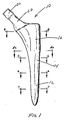
- FIG. 1 is an elevation view of the hip stem of the present invention along the anterior-posterior plane;
- FIG. 2 is an elevation view of the hip stem of the present invention along the medial-lateral plane;
- FIG. 3 is a cross-sectional view of the hip stem of the present invention along lines 3-3 of FIG. 2;
- FIG. 4 is a cross-sectional view of the hip stem of FIG. 1 along lines 4-4;
- FIG. 4a is a cross-sectional view of the hip stem of FIG. 1 along lines 4a-4a;
- FIG. 5 is a cross-sectional view of the hip stem of FIG. 1 along lines 5-5;
- FIG. 6 is a cross-sectional view of the hip stem of FIG. 1 along lines 6-6;
- FIG. 7 is a cross-sectional view of the hip stem of FIG. 1 along lines 7-7;
- FIG. 8 is an elevation view of a reamer along a medial-lateral plane with the femoral component of the present invention in phantom; and
- FIG. 9 is an elevation.view of the reamer of FIG. 8 along an anterior-posterior plane.
-
- Referring to FIGS. 1-3 there is shown the femoral component of the present invention generally denoted as 10. The
prosthesis 10 can be broken into adistal region 12, amid-stem region 14 and aproximal region 16.Distal region 12 can be described geometrically as distal parabolic section,mid-stem region 14 and the proximal generallyconical region 16 conform medially and anteriorly to the anatomy, and posteriorly and laterally fills the space created by a shaped chisel (not shown). - Referring to FIGS. 2 and 3, a
central axis 18 extends throughprosthesis 10 and generally coincides with the axis of the proximal femur.Prosthesis 10 is provided with lateral flare F at the juncture of theproximal portion 16 andsection 14, allowing for additional stress transfer to the cortex in this region. In the preferred embodimentdistal section 12 is formed as a parabola. The intent of this shape is to afford excellent fit in a large range of femurs, most notably in the anterior-posterior dimension and also improves the stress transfer to the bone pedestal often formed in this region. - A rigid reamer of predetermined shape may be used to shape the canal. Such reamers matching the distal and midshaft stem shape are shown in FIGS. 8 and 9. The reamer profile generally mimics the entire distal and midshaft shape of the femur canal, based on cadaveric studies. Reamers are currently available and presently used in medullary canal preparation such as that shown in Howmedica Inc. 1993 Catalog as part number 6059-0-510, however, these reamers are not based on the entire size and shape of the medullary canal based on studies of typical femurs. The reamer of the present invention is shaped to match approximately the lateral half of the proximal face of the implant in the area of the greater trochanter. This allows for an opening in which to more easily introduce a broach (not shown) which is used to shape the proximal femur.
- Referring to FIG. 3, a medial curvature R is defined between points A and B, meeting the reamer shape at point B. As shown in FIGS. 8 and 9, the
reamer 26 is shaped to coincide with the distal/midshaft implant shape from point B to the parabolic tip C, and laterally to point D. The parabola extends 3 cm, at which point it is blended into a conic of radius E. - The basic shape of the stem and reamer were derived from a cadaveric study in which a population of femurs were x-rayed and sectioned and the dimensions of proximal metaphysis and the medullary canal were measured and entered into a computer data base. Several reamer shapes were developed for bone groups of similar dimensions. Further iterative fitting of each group generated an average stem shape for approximately the proximal two thirds of the stem. The geometric relationships of the proximal stem cross-sections of the present invention were developed from the these studies and closely match the recorded cadaveric data. In the preferred system a kit is provided with approximately ten reamers and ten matching stems which correspond to ten size groups which cover the vast majority of all the femurs in the population of hips surveyed. The
distal portion 12 of each stem in the kit is shaped like the corresponding reamer and thus is in the form of a parabaloid having a central axis corresponding to the measured central axis. The paraboloid forms a pointed distal tip. - In the preferred embodiment the proximal lateral face of
component 10 is defined as line F-G and diverges outwardly fromaxis 18. This allows for greater femur to implant contact laterally when compared to the medial-lateral dimension of the osteotomy window. Between points D and F a transitional flare occurs, blending the proximal geometry to the distal reamer shape. Thepreferred trunnion 20 andneck 22 make an angle H of approximately 45° to theaxis 18. The trunnion allows for attachment of modular femoral heads of differing diameters and offsets. The neck is enlarged at point A providing a pseudo collar to resist subsidence. - In a preferred surgical procedure, the osteotomy is made at an angle J of 30° from a perpendicular to the
axis 18. This angle retains calcar bone stock, thereby enhancing rotational stability and stress transfer. Neck strength is also improved over a similar 45° osteotomy as the length ofneck 22 is effectively shorter. - The shape of
prosthesis 10 shown in the figures is the same as the shape of the reamer used to prepare the distal canal, being identical from point L anteriorly and around the distal tip to point M posteriorly. Analysis of femurs through planar x-ray films and 3-D computer representations has defined the proximal anterior radius P between points K and L for several implant sizes. The analysis also dictates proximal posterior radius Q, between points N and M, blending the reamer shape into the posterior aspect area. Note that radii P and Q necessitate left and right (i.e. anatomic) implants. - Referring to FIG. 4 the cross-section is defined as a transverse cut at the medal aspect of the osteotomy, perpendicular to
axis 18. Points S, T, U and V are defined as the points where the A-P and M-L profiles (FIGS. 2 and 3) bisect the plane of FIG. 4. Lines S-T and U-V are at 90° to one another. This angle does not change throughoutproximal portion 16. A radius X is defined at point B, where the medial curvature R intersects the distal reamer shape. Radius X also exists at the identical location on the reamer. Radius X is constant proximal to point B, and has its center point directly lateral to point S. The anterior radius Y is defined as an arc tangent tocircle 26 of radius X, through point V and tangent to asecond circle 30 of radius X, mirrored through line U-V. Acircle 28 of radius Z is placed at the intersection of lines S-T and U-V. The value of radius Z is that of the distance between point in and line S-T. This radius is mirrored in acircle 32 through line AA-BB, which is parallel to line U-V and through the center ofcircle 26. - The lateral shape of FIG. 4 is formed by polynomial splines DD and EE. Splines represent arcs of constantly changing radius defined in 2 or 3 dimensional space. Spline generation is available in several computer aided design (CAD) systems. These splines or arcs blend smoothly into radii Y and Z respectively. The spines also have zero slope at point T, i.e. they are parallel to line U-V. Posterior radius CC is now constructed similar to radius
Y using circles axis 18, FIG. 4 can be seen to blend into the reamer shape; this occurs at point E for splines DD and EE, and point B for radii X, Y, Z and CC. FIGS. 4A and 5 show this transition. Note the decrease in lengths of lines S-T and U-V, the decrease in the center to center dimension ofcircles circle 28. The transition to a circular section is essentially complete at FIG. 6. A section identical in location on the reamer produces a like size view. FIG. 7 describes a diameter smaller than and arranged coaxially to FIG. 6. - FIGS. 6 and 7 are cross-sections through the
distal stem region 12. Since this region is parabolic in shape, the cross-sections are generally circular.
Claims (6)
- A femoral component (10) for a hip prosthesis comprising:a distal portion (12) defining a central longitudinal axis (18) of the component for disposition within an intramedullary canal of the femur, a midstem portion (14), and a proximal portion (16) having a cross-section (4) perpendicular to the central axis (18) defining medial (AA-BB), posterior (U-AA), lateral (U-V) and anterior (V-BB) sides, characterized in that:a) said medial side (AA-BB) of said proximal portion (16) being formed as a first circular arc (AA-BB) having a center located within said cross-section (4), a corner of said cross-section formed by said posterior (U-AA) and said lateral (U-V) surfaces formed as a second circular arc (U-T) with a center on said central axis (18);b) said anterior side (V-BB) of said proximal portion (16) being an arc (Y) of a circle having its center on a first plane (U-V) through said central axis (18) and perpendicular to a second plane (T-S) containing said central axis (18) and both said centers of said first (AA-BB) and second (U-T) circular arcs and being convex in form and tangent to said first circular arc (AA-BB) at the point of intersection (BB) therewith;c) said posterior side (U-AA) of said proximal portion (16) being an arc of a circle having its center on a third plane (AA-BB) extending through the center of said first circular arc (AA-BB) and perpendicular to said second plane (S-T) containing said central axis (18) and both said centers of said first (AA-BB) and second (U-T) circular arcs and being concave in form and tangent to both said first (AA-BB) and second (U-T) circular arcs and a generally arcuate portion (DD) connecting said second circular arc (U-T) and said anterior surface (V-BB), the connection of said second circular arc (U-T) and said anterior surface (V-BB) being made at a connecting point on each of said second circular arc (T) and said anterior surface (V) and said arcuate portion (DD) forming a tangent therewith at said connecting points; andd) said femoral component (10) having a cross-section that gradually tapers from the proximal (16) to distal portion (12) while said second plane (T-S) maintains the same orientation.
- The femoral component (10) as set forth in claim 1 wherein a lateral face (G-F) of said femoral component (10) formed by said lateral surface (U-V) of said cross-section (4) diverges away from said central axis (18) when moving distally therealong.
- The femoral component (10) as set forth in claim 1 wherein said distal stem (12) has an outer surface in the form of a surface of revolution generated by rotating a parabolic cross-section about said central longitudinal axis (18).
- The femoral component (10) as set forth in claim 3 further including a mid-stem region (14) having a generally conically shaped outer surface extending from said distal portion (12) to said proximal portion (16).
- A kit for the implantation of the prosthetic femoral component (10) in a human femur comprising:a reamer having a conical shape with a maximum radius in the midshaft region of said femur, said conical shape generally mimicking the distal and midshaft shape of a population of femoral canals;a femoral component (10) as set forth in any of claims 1 to 4.
- The kit as set forth in claim 5 wherein said femoral component (10) has an anterior profile at each cross-section along substantially the entire proximal portion (16) generated by a convex arc tangent to said medial part circular form.
Applications Claiming Priority (2)
| Application Number | Priority Date | Filing Date | Title |
|---|---|---|---|
| US08/055,426 US5358534A (en) | 1993-04-29 | 1993-04-29 | Femoral component for a hip prosthesis |
| US55426 | 1993-04-29 |
Publications (2)
| Publication Number | Publication Date |
|---|---|
| EP0622061A1 EP0622061A1 (en) | 1994-11-02 |
| EP0622061B1 true EP0622061B1 (en) | 2000-06-28 |
Family
ID=21997716
Family Applications (1)
| Application Number | Title | Priority Date | Filing Date |
|---|---|---|---|
| EP94106778A Expired - Lifetime EP0622061B1 (en) | 1993-04-29 | 1994-04-29 | Femoral component for a hip prothesis |
Country Status (10)
| Country | Link |
|---|---|
| US (1) | US5358534A (en) |
| EP (1) | EP0622061B1 (en) |
| JP (1) | JPH07124187A (en) |
| KR (1) | KR940023451A (en) |
| AT (1) | ATE194065T1 (en) |
| AU (1) | AU675114B2 (en) |
| CA (1) | CA2122076A1 (en) |
| DE (2) | DE9407171U1 (en) |
| IL (1) | IL109477A (en) |
| ZA (1) | ZA942839B (en) |
Families Citing this family (23)
| Publication number | Priority date | Publication date | Assignee | Title |
|---|---|---|---|---|
| US5776204A (en) * | 1996-05-24 | 1998-07-07 | Howmedica Inc. | Asymmetric hip stem |
| EP0962199A1 (en) * | 1998-06-04 | 1999-12-08 | Sulzer Orthopädie AG | Shaft prosthesis |
| US8535382B2 (en) | 2000-04-10 | 2013-09-17 | Biomet Manufacturing, Llc | Modular radial head prostheses |
| US8920509B2 (en) | 2000-04-10 | 2014-12-30 | Biomet Manufacturing, Llc | Modular radial head prosthesis |
| US8114163B2 (en) | 2000-04-10 | 2012-02-14 | Biomet Manufacturing Corp. | Method and apparatus for adjusting height and angle for a radial head |
| DE10036986A1 (en) * | 2000-07-29 | 2002-02-07 | Klaus Draenert | Femoral neck-preserving prosthesis |
| FR2815536B1 (en) * | 2000-10-25 | 2003-07-04 | Marc Anzalone | CEMENTED ANATOMICAL FEMALE ROD |
| FR2846874B1 (en) * | 2002-11-13 | 2005-11-11 | Euros Sa | HIP PROSTHESIS |
| US7060102B2 (en) * | 2004-01-21 | 2006-06-13 | Thompson Matthew T | Femoral implant for hip arthroplasty |
| KR100566584B1 (en) * | 2004-05-28 | 2006-03-30 | 주식회사 코렌텍 | The fremoral stem for total hip arthropathy |
| US20050273109A1 (en) * | 2004-06-02 | 2005-12-08 | Minnesota Scientific, Inc. | Computer controlled reaming device |
| US9060820B2 (en) | 2005-05-18 | 2015-06-23 | Sonoma Orthopedic Products, Inc. | Segmented intramedullary fracture fixation devices and methods |
| WO2010037038A2 (en) | 2008-09-26 | 2010-04-01 | Sonoma Orthopedic Products, Inc. | Bone fixation device, tools and methods |
| US8961516B2 (en) | 2005-05-18 | 2015-02-24 | Sonoma Orthopedic Products, Inc. | Straight intramedullary fracture fixation devices and methods |
| WO2006124764A1 (en) | 2005-05-18 | 2006-11-23 | Sonoma Orthopedic Products, Inc. | Minimally invasive actuable bone fixation devices, systems and methods of use |
| US7909825B2 (en) | 2006-11-22 | 2011-03-22 | Sonoma Orthepedic Products, Inc. | Fracture fixation device, tools and methods |
| US20080200990A1 (en) * | 2007-02-16 | 2008-08-21 | Mctighe Timothy | Tissue sparing implant |
| EP2299917A1 (en) | 2008-06-10 | 2011-03-30 | Sonoma Orthopedic Products, Inc. | Fracture fixation device, tools and methods |
| US20140257510A1 (en) | 2013-03-05 | 2014-09-11 | Howmedica Osteonics Corp. | Anatomic monolithic hip implant system |
| US9770278B2 (en) | 2014-01-17 | 2017-09-26 | Arthrex, Inc. | Dual tip guide wire |
| US9814499B2 (en) | 2014-09-30 | 2017-11-14 | Arthrex, Inc. | Intramedullary fracture fixation devices and methods |
| US20170079800A1 (en) * | 2015-09-22 | 2017-03-23 | Michael Messieh | Hybrid Femoral Component Design for a Hip Prosthesis and Method of Stem Insertion |
| CN112618111B (en) * | 2020-12-14 | 2021-09-21 | 徐州医科大学 | Femoral stem prosthesis design method based on vein skeleton structure |
Family Cites Families (17)
| Publication number | Priority date | Publication date | Assignee | Title |
|---|---|---|---|---|
| US3965490A (en) * | 1974-11-14 | 1976-06-29 | Howmedica, Inc. | Femoral insert for hip joint prosthesis |
| DE3015690A1 (en) * | 1980-04-24 | 1981-10-29 | Waldemar Link (Gmbh & Co), 2000 Hamburg | HIP JOINT PROSTHESIS WITH A SHAFT TO BE INSERTED IN THE MARKING CHANNEL OF THE THIGH BONE |
| US4752296A (en) * | 1983-05-06 | 1988-06-21 | Buechel Frederick F | Prosthesis with interlocking fixation and providing reduction of stress shielding |
| US4589883A (en) * | 1983-06-06 | 1986-05-20 | Pfizer Hospital Products Group, Inc. | Femoral hip prosthesis |
| CH668549A5 (en) * | 1985-11-14 | 1989-01-13 | Sulzer Ag | STRAIGHTNESS FOR A FEMUR HEAD PROSTHESIS. |
| FR2618667A1 (en) * | 1987-07-30 | 1989-02-03 | Verola Jean | Self-immobilising femoral rod for hip prosthesis |
| US4813963A (en) * | 1987-08-24 | 1989-03-21 | Zimmer, Inc. | Femoral component for a hip prosthesis |
| NL8702626A (en) * | 1987-11-03 | 1989-06-01 | Orthopaedic Tech Bv | METHOD FOR FORMING A GEOMETRY OF AN ENDOPROTHESIS, A FEMUR HEAD PROSTHESIS, AN ACETABULUM PROSTHESIS, A METHOD FOR BOTTING A FEMUR HEAD PROSTHESIS AND AN INSTRUMENT FOR PLACING ACROTHESES |
| JPH0292352A (en) * | 1988-09-29 | 1990-04-03 | Aisin Seiki Co Ltd | Artificial condyle for hip joint |
| US5002580A (en) * | 1988-10-07 | 1991-03-26 | Pfizer Hospital Products Group, Inc. | Prosthetic device and method of implantation |
| AT393215B (en) * | 1989-03-16 | 1991-09-10 | Boehler Gmbh | BONE IMPLANT |
| GB8921008D0 (en) * | 1989-09-15 | 1989-11-01 | Walker Peter S | Skeletal implants |
| FR2662932B1 (en) * | 1990-06-07 | 1997-09-05 | Denis Godeau | FEMALE PROSTHESIS. |
| FR2666737B1 (en) * | 1990-09-18 | 1992-12-18 | Medinov Sa | HIP PROSTHETIC ASSEMBLY. |
| US5181930A (en) * | 1991-04-10 | 1993-01-26 | Pfizer Hospital Products Group, Inc. | Composite orthopedic implant |
| DE4221442A1 (en) * | 1992-06-30 | 1994-01-05 | Keramed Medizintechnik Gmbh | Metal stem for cemented hip joint prosthesis - has cross-section corresp. in its distal portion to femur cavity prepared by basting |
| DE4234351A1 (en) * | 1992-10-12 | 1994-05-11 | Draenert Klaus | Stem of a femoral component of a hip joint endoprosthesis |
-
1993
- 1993-04-29 US US08/055,426 patent/US5358534A/en not_active Expired - Lifetime
-
1994
- 1994-04-25 ZA ZA942839A patent/ZA942839B/en unknown
- 1994-04-25 CA CA002122076A patent/CA2122076A1/en not_active Abandoned
- 1994-04-28 AU AU60775/94A patent/AU675114B2/en not_active Ceased
- 1994-04-28 IL IL109477A patent/IL109477A/en not_active IP Right Cessation
- 1994-04-28 KR KR1019940009143A patent/KR940023451A/en active IP Right Grant
- 1994-04-29 AT AT94106778T patent/ATE194065T1/en not_active IP Right Cessation
- 1994-04-29 DE DE9407171U patent/DE9407171U1/en not_active Expired - Lifetime
- 1994-04-29 DE DE69425015T patent/DE69425015T2/en not_active Expired - Fee Related
- 1994-04-29 EP EP94106778A patent/EP0622061B1/en not_active Expired - Lifetime
- 1994-05-02 JP JP6093523A patent/JPH07124187A/en active Pending
Also Published As
| Publication number | Publication date |
|---|---|
| IL109477A (en) | 1998-02-08 |
| IL109477A0 (en) | 1994-07-31 |
| AU675114B2 (en) | 1997-01-23 |
| EP0622061A1 (en) | 1994-11-02 |
| DE69425015T2 (en) | 2001-03-08 |
| CA2122076A1 (en) | 1994-10-30 |
| JPH07124187A (en) | 1995-05-16 |
| DE9407171U1 (en) | 1994-09-29 |
| US5358534A (en) | 1994-10-25 |
| DE69425015D1 (en) | 2000-08-03 |
| ATE194065T1 (en) | 2000-07-15 |
| AU6077594A (en) | 1994-11-03 |
| KR940023451A (en) | 1994-11-17 |
| ZA942839B (en) | 1995-02-17 |
Similar Documents
| Publication | Publication Date | Title |
|---|---|---|
| EP0622061B1 (en) | Femoral component for a hip prothesis | |
| US11219467B2 (en) | Surgical technique and instrumentation for minimal incision hip arthroplasty surgery | |
| US5888210A (en) | Stem of a femoral component of a hip joint endoprosthesis | |
| US5290315A (en) | Oblong acetabular cup | |
| US6139584A (en) | Proximal femoral sleeve for a revision hip prosthesis | |
| US6702822B1 (en) | Method and apparatus for fitting a prosthesis to a bone | |
| EP0985385B1 (en) | Implantable prosthesis with bone engaging ribs | |
| CA1291597C (en) | Long stem hip implant | |
| US7494509B1 (en) | Method and apparatus for providing a short-stemmed hip prosthesis | |
| CA2730564C (en) | Femoral head prosthesis | |
| IE55218B1 (en) | Femoral hip prosthesis | |
| CA2942523A1 (en) | Femoral hip stem | |
| Team | The science of simplicity |
Legal Events
| Date | Code | Title | Description |
|---|---|---|---|
| PUAI | Public reference made under article 153(3) epc to a published international application that has entered the european phase |
Free format text: ORIGINAL CODE: 0009012 |
|
| AK | Designated contracting states |
Kind code of ref document: A1 Designated state(s): AT BE CH DE DK ES FR GB GR IE IT LI LU NL PT SE |
|
| 17P | Request for examination filed |
Effective date: 19950427 |
|
| 17Q | First examination report despatched |
Effective date: 19970304 |
|
| GRAG | Despatch of communication of intention to grant |
Free format text: ORIGINAL CODE: EPIDOS AGRA |
|
| RAP1 | Party data changed (applicant data changed or rights of an application transferred) |
Owner name: HUNGERFORD, DAVID S. Owner name: HEDLEY, ANTHONY K. Owner name: STRYKER TECHNOLOGIES CORPORATION |
|
| GRAG | Despatch of communication of intention to grant |
Free format text: ORIGINAL CODE: EPIDOS AGRA |
|
| GRAH | Despatch of communication of intention to grant a patent |
Free format text: ORIGINAL CODE: EPIDOS IGRA |
|
| GRAH | Despatch of communication of intention to grant a patent |
Free format text: ORIGINAL CODE: EPIDOS IGRA |
|
| GRAA | (expected) grant |
Free format text: ORIGINAL CODE: 0009210 |
|
| AK | Designated contracting states |
Kind code of ref document: B1 Designated state(s): AT BE CH DE DK ES FR GB GR IE IT LI LU NL PT SE |
|
| PG25 | Lapsed in a contracting state [announced via postgrant information from national office to epo] |
Ref country code: NL Free format text: LAPSE BECAUSE OF FAILURE TO SUBMIT A TRANSLATION OF THE DESCRIPTION OR TO PAY THE FEE WITHIN THE PRESCRIBED TIME-LIMIT Effective date: 20000628 Ref country code: GR Free format text: LAPSE BECAUSE OF NON-PAYMENT OF DUE FEES Effective date: 20000628 Ref country code: ES Free format text: THE PATENT HAS BEEN ANNULLED BY A DECISION OF A NATIONAL AUTHORITY Effective date: 20000628 Ref country code: BE Free format text: LAPSE BECAUSE OF FAILURE TO SUBMIT A TRANSLATION OF THE DESCRIPTION OR TO PAY THE FEE WITHIN THE PRESCRIBED TIME-LIMIT Effective date: 20000628 Ref country code: AT Free format text: LAPSE BECAUSE OF FAILURE TO SUBMIT A TRANSLATION OF THE DESCRIPTION OR TO PAY THE FEE WITHIN THE PRESCRIBED TIME-LIMIT Effective date: 20000628 |
|
| REF | Corresponds to: |
Ref document number: 194065 Country of ref document: AT Date of ref document: 20000715 Kind code of ref document: T |
|
| ITF | It: translation for a ep patent filed | ||
| REG | Reference to a national code |
Ref country code: CH Ref legal event code: EP |
|
| REG | Reference to a national code |
Ref country code: IE Ref legal event code: FG4D |
|
| ET | Fr: translation filed | ||
| REF | Corresponds to: |
Ref document number: 69425015 Country of ref document: DE Date of ref document: 20000803 |
|
| PG25 | Lapsed in a contracting state [announced via postgrant information from national office to epo] |
Ref country code: SE Free format text: LAPSE BECAUSE OF FAILURE TO SUBMIT A TRANSLATION OF THE DESCRIPTION OR TO PAY THE FEE WITHIN THE PRESCRIBED TIME-LIMIT Effective date: 20000928 Ref country code: PT Free format text: LAPSE BECAUSE OF FAILURE TO SUBMIT A TRANSLATION OF THE DESCRIPTION OR TO PAY THE FEE WITHIN THE PRESCRIBED TIME-LIMIT Effective date: 20000928 Ref country code: DK Free format text: LAPSE BECAUSE OF FAILURE TO SUBMIT A TRANSLATION OF THE DESCRIPTION OR TO PAY THE FEE WITHIN THE PRESCRIBED TIME-LIMIT Effective date: 20000928 |
|
| REG | Reference to a national code |
Ref country code: CH Ref legal event code: NV Representative=s name: KIRKER & CIE SA |
|
| NLV1 | Nl: lapsed or annulled due to failure to fulfill the requirements of art. 29p and 29m of the patents act | ||
| PLBE | No opposition filed within time limit |
Free format text: ORIGINAL CODE: 0009261 |
|
| STAA | Information on the status of an ep patent application or granted ep patent |
Free format text: STATUS: NO OPPOSITION FILED WITHIN TIME LIMIT |
|
| PG25 | Lapsed in a contracting state [announced via postgrant information from national office to epo] |
Ref country code: LU Free format text: LAPSE BECAUSE OF NON-PAYMENT OF DUE FEES Effective date: 20010429 |
|
| PG25 | Lapsed in a contracting state [announced via postgrant information from national office to epo] |
Ref country code: IE Free format text: LAPSE BECAUSE OF NON-PAYMENT OF DUE FEES Effective date: 20010430 |
|
| 26N | No opposition filed | ||
| REG | Reference to a national code |
Ref country code: GB Ref legal event code: IF02 |
|
| REG | Reference to a national code |
Ref country code: IE Ref legal event code: MM4A |
|
| PGFP | Annual fee paid to national office [announced via postgrant information from national office to epo] |
Ref country code: GB Payment date: 20030313 Year of fee payment: 10 |
|
| PGFP | Annual fee paid to national office [announced via postgrant information from national office to epo] |
Ref country code: FR Payment date: 20030403 Year of fee payment: 10 |
|
| PGFP | Annual fee paid to national office [announced via postgrant information from national office to epo] |
Ref country code: DE Payment date: 20030430 Year of fee payment: 10 |
|
| PGFP | Annual fee paid to national office [announced via postgrant information from national office to epo] |
Ref country code: CH Payment date: 20030605 Year of fee payment: 10 |
|
| PG25 | Lapsed in a contracting state [announced via postgrant information from national office to epo] |
Ref country code: GB Free format text: LAPSE BECAUSE OF NON-PAYMENT OF DUE FEES Effective date: 20040429 |
|
| PG25 | Lapsed in a contracting state [announced via postgrant information from national office to epo] |
Ref country code: LI Free format text: LAPSE BECAUSE OF NON-PAYMENT OF DUE FEES Effective date: 20040430 Ref country code: CH Free format text: LAPSE BECAUSE OF NON-PAYMENT OF DUE FEES Effective date: 20040430 |
|
| PG25 | Lapsed in a contracting state [announced via postgrant information from national office to epo] |
Ref country code: DE Free format text: LAPSE BECAUSE OF NON-PAYMENT OF DUE FEES Effective date: 20041103 |
|
| REG | Reference to a national code |
Ref country code: CH Ref legal event code: PL |
|
| GBPC | Gb: european patent ceased through non-payment of renewal fee |
Effective date: 20040429 |
|
| PG25 | Lapsed in a contracting state [announced via postgrant information from national office to epo] |
Ref country code: FR Free format text: LAPSE BECAUSE OF NON-PAYMENT OF DUE FEES Effective date: 20041231 |
|
| REG | Reference to a national code |
Ref country code: FR Ref legal event code: ST |
|
| PG25 | Lapsed in a contracting state [announced via postgrant information from national office to epo] |
Ref country code: IT Free format text: LAPSE BECAUSE OF NON-PAYMENT OF DUE FEES Effective date: 20050429 |