EP0622038B1 - Verbesserter Mehrzweckwagen - Google Patents
Verbesserter Mehrzweckwagen Download PDFInfo
- Publication number
- EP0622038B1 EP0622038B1 EP92810977A EP92810977A EP0622038B1 EP 0622038 B1 EP0622038 B1 EP 0622038B1 EP 92810977 A EP92810977 A EP 92810977A EP 92810977 A EP92810977 A EP 92810977A EP 0622038 B1 EP0622038 B1 EP 0622038B1
- Authority
- EP
- European Patent Office
- Prior art keywords
- rod
- supports
- frame
- carriage
- toothed member
- Prior art date
- Legal status (The legal status is an assumption and is not a legal conclusion. Google has not performed a legal analysis and makes no representation as to the accuracy of the status listed.)
- Expired - Lifetime
Links
Images





Classifications
-
- A—HUMAN NECESSITIES
- A47—FURNITURE; DOMESTIC ARTICLES OR APPLIANCES; COFFEE MILLS; SPICE MILLS; SUCTION CLEANERS IN GENERAL
- A47C—CHAIRS; SOFAS; BEDS
- A47C13/00—Convertible chairs, stools or benches
Definitions
- This invention relates to an improved multi-purpose carriage.
- a multi-purpose carriage is known from US-A-4'369'987.
- the carriage is used simultaneously as a foldable wheeled chair and luggage carrier, but is not transformable from one single purpose use to another.
- This invention relates to an improved multi-purpose carriage.
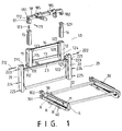
- the present invention mainly comprises an upper frame 10, a lower frame 20, a compound frame 30, a plurality of wheels 40, a seat cushion 50, a wheel frame 70, a seat 80 and a foot rest 90.
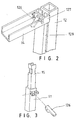
- the upper frame 10 is provided with a left upper support 11 and a right upper support 12 respectively having a left toothed member 111 and a right toothed member 121 at the lower end.
- the left lower support 21 and the right lower support 22 are respectively provided at the upper end with a first toothed member 211 and a second toothed member 221 which are respectively connected with the left toothed member 111 and the right toothed member 112 of the left upper support 11 and the right upper support 12 by screws 212 and 222.
- the upper supports 11 and 12 respectively provided with fixing blocks 113 and 124, sliders 114 and 127, and guiding racks 115 and 128.
- a transverse rod 14 is mounted between the fixing block 113 and the slider 127.
- a transverse rod 13 is fitted between the slider 114 and the fixing block 124. Hence, the transverse rods 14 and 13 may be moved up and down along the guiding racks 115 and 128.
- the sliders 127 and 114 are each provided with a positioning device 126 which designed to fixedly mount the sliders 127 and 114 on the guiding racks 128 and 115 respectively.
- the upper supports 11 and 12 are tubular members in which are inserted telescopic rods 15 and 16. Further, the supports 11 and 12 are each provided with a positioning device 126 for keeping the position of the telescopic rods 15 and 16.
- the upper end of the telescopic rod 15 is pivotally connected with a connector 17 by a pin 171.
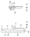
- the top of the connector 17 has a hole 172 aligned with a hole 181 of a head rest rod 18 and the connector 17 is connected with the head rest rod 18 by a rivet 173.
- the right end of the head rest rod 18 has a lug 182 inserted into the upper end of the telescopic rod 16 and a pin 184 inserted into a hole 129 of the telescopic rod 16 so that the head rest rod 18 may be connected with the telescopic rod 16 (see FIG. 5).
- the head rest rod 18 is provided with an adjustable rest 185 (see FIG. 6) which has a positioning assembly 201 which has a fixing plate 202 pivotally mounted on two lugs 188.
- the adjustable rest 185 As the adjustable rest 185 is moved to the desired position, simple press the fixing plate 202 to fix the adjustable rest 185 on the head rest rod 18. When desired to regulate the position of the adjustable rest 185, just pull up the fixing plate 201 to enable the adjustable rest 185 to move.
- the adjustable rest 185 has a swivel set 190 which has a rod 194 pivotally connected with a support bar 193 which is provided with a soft cushion 195.
- the adjustable rest 185 is provided with a pair of lugs 196 pivotally connected with a Z-shaped rod 198 urged by a spring 197 so that the support bar 193 may be controlled by pressing the Z-shaped rod thereby controlling the position of the soft cushion 195.
- FIG. 9 shows another working view of the present invention wherein the upper frame 10 is pivotally connected with the lower frame 20 and the compound frame 30 is engaged with the lower supports 21 and 22 by engaging the C-shaped openings 301 and 302 with the screws 225 and 224.
- the compound frame 30 has a rod M at both sides and a rod L under each rod M.
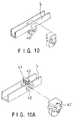
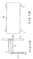
- the bottom of the rod L is provided with two wheel assemblies 40 and the rod L has a spring-loaded means 41 so that when the means 41 is pressed, a pin 43 of the means 41 will be inserted into a hole 42 of the wheel assembly 40 thereby keeping the wheel assembly 40 in position.
- FIG. 11 shows another working view of the present invention wherein the wheel assemblies 40 are dismantled from the compound frame 30 and then the compound frame 30 is detached from the lower supports 21 and 22. Then, the compound frame 30 is turned over so that the rod M is located under the rod L. Then, the rod M is extended downwards and turned to have an angle of 90 degrees with the rod L. Thereafter, the C-shaped opening of the rod L is engaged with the screw 223 of the lower support 22. Then, the linking rod R is expanded and the C-shaped opening 303 is engaged with the screw 224 of the lower support 22 so as to reinforce the compound frame 30 and the lower frame 20. Then, the cushion 50 is mounted between the two rods L.
- FIG. 13 shows a third working view of the present invention, wherein the upper frame 10 is turned backwards making an angle of 90 degrees with the lower frame 20 and the telescopic rods 15 and 18 are supported by the supporting frame 70. Then, the rods A and B in the rod L are drawn out to form another supporting frame and a foot cushion 90 is fitted between the two rods A.
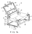
- FIG. 14 shows a fourth working view of the present invention wherein the compound frame 30 is dismantled and the rod N in the rod M is pulled out making an angle of 90 degrees with the rod M and parallel to rod L. Then, the C-shaped opening 302 of the rod N is engaged with the screw 224 of the lower support 21. Then, the transverse rod 23 and 32, and two rods N form a rectangular frame and a baby seat 80 is mounted thereon to form a baby seat.
Landscapes
- Carriages For Children, Sleds, And Other Hand-Operated Vehicles (AREA)
- Warehouses Or Storage Devices (AREA)
Claims (3)
- Fahrbares Mehrzweckgestell, dadurch gekennzeichnet, dass es nachfolgende Teile aufweist:
einen oberen Rahmen (10) mit zwei Stützen (11,12), die an ihrem unteren Ende je mit einem verzahnten Element (111,112) versehen sind, wobei Querstäbe (13,14) die Stützen (11,12) miteinander verbinden und die Stützen (11,12) je einen Halteblock (113,114) und ein Gleitstück (114,127) sowie je eine Führungsschiene (115,128) haben, wobei die Stützen mit teleskopisch einschiebbaren Stangen (15,16) versehen sind und jedes Gleitstück (114,127) mit einer Feststellvorrichtung zum Halten an den Führungsschienen (115,128) versehen ist, ferner mit einer Stange (18) für Kopfstützen, welche schwenkbar mit den oberen Stützen (11,12) verbunden ist und einstellbare Kopfstützen (185) trägt, ferner mit einem unteren Rahmen (20) mit zwei unteren Stützen (21,22), die an ihrem oberen Ende je mit einem verzahnten Element (211,221) versehen sind, welches mit den verzahnten Elementen (111,112) des oberen Rahmens im Eingriff ist; und einen zusammengebauten Rahmen (30), welcher mit dem unteren Rahmen (20) verbunden ist und aus zwei teleskopisch ineinandergreifenden Stäben (M,A,B) besteht, die je mit einem L-förmigen Stab (L) verbunden sind, wobei dieser L-förmige Stab (L) mit mehreren Radsätzen (40) verbunden ist. - Fahrbares Mehrzweckgestell nach Patentanspruch 1, dadurch gekennzeichnet, dass das Ende der teleskopischen Stange und des L-förmigen Stabes eine C-förmige Oeffnung aufweisen, mit welcher sie mit den unteren Stützen des unteren Rahmens mittels eines Elementes mit elliptischem Querschnitt verbunden sind, so dass die teleskopische Stange und der L-förmige Stab durch einfaches Drehen des Elementes mit den unteren Stützen des unteren Rahmens verbindbar oder davon lösbar sind.
- Fahrbares Mehrzweckgestell nach Patentanspruch 1, dadurch gekennzeichnet, dass es auch noch einen Tragrahmen umfasst, welcher die teleskopischen Stäbe stützt.
Priority Applications (6)
| Application Number | Priority Date | Filing Date | Title |
|---|---|---|---|
| US07/987,181 US5433459A (en) | 1992-12-08 | 1992-12-08 | Multi-purpose carriage |
| DE69202061T DE69202061T2 (de) | 1992-12-08 | 1992-12-10 | Verbesserter Mehrzweckwagen. |
| CA002085021A CA2085021A1 (en) | 1992-12-08 | 1992-12-10 | Multi-purpose carriage |
| EP92810977A EP0622038B1 (de) | 1992-12-08 | 1992-12-10 | Verbesserter Mehrzweckwagen |
| AT92810977T ATE120937T1 (de) | 1992-12-08 | 1992-12-10 | Verbesserter mehrzweckwagen. |
| AU30193/92A AU640100B3 (en) | 1992-12-08 | 1992-12-16 | An improved multi-purpose carriage |
Applications Claiming Priority (4)
| Application Number | Priority Date | Filing Date | Title |
|---|---|---|---|
| US07/987,181 US5433459A (en) | 1992-12-08 | 1992-12-08 | Multi-purpose carriage |
| CA002085021A CA2085021A1 (en) | 1992-12-08 | 1992-12-10 | Multi-purpose carriage |
| EP92810977A EP0622038B1 (de) | 1992-12-08 | 1992-12-10 | Verbesserter Mehrzweckwagen |
| AU30193/92A AU640100B3 (en) | 1992-12-08 | 1992-12-16 | An improved multi-purpose carriage |
Publications (2)
| Publication Number | Publication Date |
|---|---|
| EP0622038A1 EP0622038A1 (de) | 1994-11-02 |
| EP0622038B1 true EP0622038B1 (de) | 1995-04-12 |
Family
ID=27422899
Family Applications (1)
| Application Number | Title | Priority Date | Filing Date |
|---|---|---|---|
| EP92810977A Expired - Lifetime EP0622038B1 (de) | 1992-12-08 | 1992-12-10 | Verbesserter Mehrzweckwagen |
Country Status (6)
| Country | Link |
|---|---|
| US (1) | US5433459A (de) |
| EP (1) | EP0622038B1 (de) |
| AT (1) | ATE120937T1 (de) |
| AU (1) | AU640100B3 (de) |
| CA (1) | CA2085021A1 (de) |
| DE (1) | DE69202061T2 (de) |
Families Citing this family (4)
| Publication number | Priority date | Publication date | Assignee | Title |
|---|---|---|---|---|
| US5577744A (en) * | 1995-05-09 | 1996-11-26 | Parks; James E. | Utility cart |
| US6142488A (en) * | 1998-07-01 | 2000-11-07 | Magna Tech, Inc. | Recreation vehicle stabilizing system |
| FR2838941B1 (fr) * | 2002-04-29 | 2004-07-02 | Yvan Daumas | Rallonges doubles repliables et meubles transformables les incorporant |
| CN105216668A (zh) * | 2014-06-26 | 2016-01-06 | 李宛豫 | 能翻转的车用座椅框架及其组件 |
Family Cites Families (8)
| Publication number | Priority date | Publication date | Assignee | Title |
|---|---|---|---|---|
| US2957700A (en) * | 1958-07-24 | 1960-10-25 | Arthur W Beaurline | Golf carts |
| US3137511A (en) * | 1961-04-05 | 1964-06-16 | Weil | Stretcher chair |
| AU477801B2 (en) * | 1972-11-09 | 1975-05-08 | Hawker Dehavilland Australia Pty. Limited | Patient transfer system for air and/or road ambulance use |
| US4369987A (en) * | 1981-03-16 | 1983-01-25 | Witherell Nancy B | Folding wheeled chair/luggage carrier |
| US4505495A (en) * | 1982-12-14 | 1985-03-19 | Janet Mary Penrose Foss | Portable, foldable and convertible luggage trolley |
| US4997200A (en) * | 1990-03-13 | 1991-03-05 | Earls Richard J | Combination wheelchair-gurney apparatus |
| US5050899A (en) * | 1990-07-06 | 1991-09-24 | Stensby Harold F | Medical crash-chair and treatment table |
| US5213360A (en) * | 1992-06-17 | 1993-05-25 | Ting Yi Enterprise Co., Ltd. | Push car |
-
1992
- 1992-12-08 US US07/987,181 patent/US5433459A/en not_active Expired - Fee Related
- 1992-12-10 EP EP92810977A patent/EP0622038B1/de not_active Expired - Lifetime
- 1992-12-10 CA CA002085021A patent/CA2085021A1/en not_active Abandoned
- 1992-12-10 AT AT92810977T patent/ATE120937T1/de not_active IP Right Cessation
- 1992-12-10 DE DE69202061T patent/DE69202061T2/de not_active Expired - Fee Related
- 1992-12-16 AU AU30193/92A patent/AU640100B3/en not_active Ceased
Also Published As
| Publication number | Publication date |
|---|---|
| DE69202061D1 (de) | 1995-05-18 |
| EP0622038A1 (de) | 1994-11-02 |
| US5433459A (en) | 1995-07-18 |
| AU640100B3 (en) | 1993-08-12 |
| ATE120937T1 (de) | 1995-04-15 |
| DE69202061T2 (de) | 1995-08-24 |
| CA2085021A1 (en) | 1994-06-11 |
Similar Documents
| Publication | Publication Date | Title |
|---|---|---|
| US6267406B1 (en) | Structure of folding-collapsible double-seat baby stroller | |
| US4615523A (en) | Child's walker with height adjustment apparatus | |
| US4805928A (en) | Reclining mechanism of baby carriage | |
| US4832361A (en) | Foldable baby carriage | |
| CN201958342U (zh) | 可转换使用模式的摇椅 | |
| US5062650A (en) | Multi-function chair | |
| JPH08206980A (ja) | 調節可能な作業台 | |
| US2968338A (en) | Child's convertible furniture article | |
| US5433459A (en) | Multi-purpose carriage | |
| GB2309944A (en) | Folding collapsible golf cart frame | |
| US6048037A (en) | Detachable device of a stroller wheel | |
| US3109666A (en) | Convertible and foldable baby apparatus | |
| CN201961351U (zh) | 设有第二座位靠背倾角调整机构的婴儿车 | |
| CN215502096U (zh) | 一种托盘及椅子 | |
| US4762363A (en) | Exercise chair | |
| CN107176234B (zh) | 电动车、自行车前置可折叠儿童座椅 | |
| US5330253A (en) | Mechanism for modulating height of legs of chair for small child | |
| CN218967101U (zh) | 一种可调节座位位置的儿童车 | |
| US6871912B1 (en) | Highchair | |
| CN211468657U (zh) | 折叠装置及具有折叠装置的滑板车 | |
| CN223045813U (zh) | 一种儿童推车的座位组件 | |
| CN215793992U (zh) | 儿童车 | |
| CN107284508B (zh) | 一种婴儿手推车附加载具的座椅调节结构 | |
| CN220349773U (zh) | 遛娃推车的座椅折叠结构 | |
| CN219277707U (zh) | 一种升降结构及滑板车 |
Legal Events
| Date | Code | Title | Description |
|---|---|---|---|
| PUAI | Public reference made under article 153(3) epc to a published international application that has entered the european phase |
Free format text: ORIGINAL CODE: 0009012 |
|
| 17P | Request for examination filed |
Effective date: 19931115 |
|
| AK | Designated contracting states |
Kind code of ref document: A1 Designated state(s): AT BE CH DE DK ES FR GB GR IE IT LI LU MC NL PT SE |
|
| GRAA | (expected) grant |
Free format text: ORIGINAL CODE: 0009210 |
|
| AK | Designated contracting states |
Kind code of ref document: B1 Designated state(s): AT BE CH DE DK ES FR GB GR IE IT LI LU MC NL PT SE |
|
| PG25 | Lapsed in a contracting state [announced via postgrant information from national office to epo] |
Ref country code: NL Free format text: LAPSE BECAUSE OF FAILURE TO SUBMIT A TRANSLATION OF THE DESCRIPTION OR TO PAY THE FEE WITHIN THE PRESCRIBED TIME-LIMIT Effective date: 19950412 Ref country code: MC Free format text: LAPSE BECAUSE OF NON-PAYMENT OF DUE FEES Effective date: 19950412 Ref country code: LI Effective date: 19950412 Ref country code: IT Free format text: LAPSE BECAUSE OF FAILURE TO SUBMIT A TRANSLATION OF THE DESCRIPTION OR TO PAY THE FEE WITHIN THE PRE;WARNING: LAPSES OF ITALIAN PATENTS WITH EFFECTIVE DATE BEFORE 2007 MAY HAVE OCCURRED AT ANY TIME BEFORE 2007. THE CORRECT EFFECTIVE DATE MAY BE DIFFERENT FROM THE ONE RECORDED.SCRIBED TIME-LIMIT Effective date: 19950412 Ref country code: GR Free format text: LAPSE BECAUSE OF FAILURE TO SUBMIT A TRANSLATION OF THE DESCRIPTION OR TO PAY THE FEE WITHIN THE PRESCRIBED TIME-LIMIT Effective date: 19950412 Ref country code: FR Effective date: 19950412 Ref country code: ES Free format text: THE PATENT HAS BEEN ANNULLED BY A DECISION OF A NATIONAL AUTHORITY Effective date: 19950412 Ref country code: DK Effective date: 19950412 Ref country code: CH Effective date: 19950412 Ref country code: BE Effective date: 19950412 Ref country code: AT Effective date: 19950412 |
|
| REF | Corresponds to: |
Ref document number: 120937 Country of ref document: AT Date of ref document: 19950415 Kind code of ref document: T |
|
| REG | Reference to a national code |
Ref country code: IE Ref legal event code: FG4D Free format text: 63588 |
|
| REF | Corresponds to: |
Ref document number: 69202061 Country of ref document: DE Date of ref document: 19950518 |
|
| PG25 | Lapsed in a contracting state [announced via postgrant information from national office to epo] |
Ref country code: SE Effective date: 19950712 Ref country code: PT Effective date: 19950712 |
|
| EN | Fr: translation not filed | ||
| NLV1 | Nl: lapsed or annulled due to failure to fulfill the requirements of art. 29p and 29m of the patents act | ||
| PG25 | Lapsed in a contracting state [announced via postgrant information from national office to epo] |
Ref country code: LU Free format text: LAPSE BECAUSE OF NON-PAYMENT OF DUE FEES Effective date: 19951231 Ref country code: IE Free format text: LAPSE BECAUSE OF NON-PAYMENT OF DUE FEES Effective date: 19951231 |
|
| PLBE | No opposition filed within time limit |
Free format text: ORIGINAL CODE: 0009261 |
|
| 26N | No opposition filed | ||
| PG25 | Lapsed in a contracting state [announced via postgrant information from national office to epo] |
Ref country code: DE Effective date: 19960903 |
|
| PG25 | Lapsed in a contracting state [announced via postgrant information from national office to epo] |
Ref country code: GB Effective date: 19961210 |
|
| GBPC | Gb: european patent ceased through non-payment of renewal fee |
Effective date: 19961210 |