EP0621621A2 - Current limiting fuses - Google Patents
Current limiting fuses Download PDFInfo
- Publication number
- EP0621621A2 EP0621621A2 EP94302904A EP94302904A EP0621621A2 EP 0621621 A2 EP0621621 A2 EP 0621621A2 EP 94302904 A EP94302904 A EP 94302904A EP 94302904 A EP94302904 A EP 94302904A EP 0621621 A2 EP0621621 A2 EP 0621621A2
- Authority
- EP
- European Patent Office
- Prior art keywords
- housing
- portions
- terminals
- pieces
- fuse according
- Prior art date
- Legal status (The legal status is an assumption and is not a legal conclusion. Google has not performed a legal analysis and makes no representation as to the accuracy of the status listed.)
- Withdrawn
Links
Images


Classifications
-
- H—ELECTRICITY
- H01—ELECTRIC ELEMENTS
- H01H—ELECTRIC SWITCHES; RELAYS; SELECTORS; EMERGENCY PROTECTIVE DEVICES
- H01H85/00—Protective devices in which the current flows through a part of fusible material and this current is interrupted by displacement of the fusible material when this current becomes excessive
- H01H85/02—Details
- H01H85/04—Fuses, i.e. expendable parts of the protective device, e.g. cartridges
- H01H85/05—Component parts thereof
- H01H85/143—Electrical contacts; Fastening fusible members to such contacts
- H01H85/153—Knife-blade-end contacts
-
- H—ELECTRICITY
- H01—ELECTRIC ELEMENTS
- H01H—ELECTRIC SWITCHES; RELAYS; SELECTORS; EMERGENCY PROTECTIVE DEVICES
- H01H85/00—Protective devices in which the current flows through a part of fusible material and this current is interrupted by displacement of the fusible material when this current becomes excessive
- H01H85/02—Details
- H01H85/04—Fuses, i.e. expendable parts of the protective device, e.g. cartridges
- H01H85/05—Component parts thereof
- H01H85/165—Casings
-
- H—ELECTRICITY
- H01—ELECTRIC ELEMENTS
- H01H—ELECTRIC SWITCHES; RELAYS; SELECTORS; EMERGENCY PROTECTIVE DEVICES
- H01H69/00—Apparatus or processes for the manufacture of emergency protective devices
- H01H69/02—Manufacture of fuses
- H01H2069/027—Manufacture of fuses using ultrasonic techniques
-
- H—ELECTRICITY
- H01—ELECTRIC ELEMENTS
- H01H—ELECTRIC SWITCHES; RELAYS; SELECTORS; EMERGENCY PROTECTIVE DEVICES
- H01H85/00—Protective devices in which the current flows through a part of fusible material and this current is interrupted by displacement of the fusible material when this current becomes excessive
- H01H85/02—Details
- H01H85/04—Fuses, i.e. expendable parts of the protective device, e.g. cartridges
- H01H85/05—Component parts thereof
- H01H85/055—Fusible members
- H01H85/08—Fusible members characterised by the shape or form of the fusible member
- H01H85/10—Fusible members characterised by the shape or form of the fusible member with constriction for localised fusing
-
- H—ELECTRICITY
- H01—ELECTRIC ELEMENTS
- H01H—ELECTRIC SWITCHES; RELAYS; SELECTORS; EMERGENCY PROTECTIVE DEVICES
- H01H85/00—Protective devices in which the current flows through a part of fusible material and this current is interrupted by displacement of the fusible material when this current becomes excessive
- H01H85/02—Details
- H01H85/04—Fuses, i.e. expendable parts of the protective device, e.g. cartridges
- H01H85/05—Component parts thereof
- H01H85/055—Fusible members
- H01H85/12—Two or more separate fusible members in parallel
-
- H—ELECTRICITY
- H01—ELECTRIC ELEMENTS
- H01H—ELECTRIC SWITCHES; RELAYS; SELECTORS; EMERGENCY PROTECTIVE DEVICES
- H01H85/00—Protective devices in which the current flows through a part of fusible material and this current is interrupted by displacement of the fusible material when this current becomes excessive
- H01H85/02—Details
- H01H85/04—Fuses, i.e. expendable parts of the protective device, e.g. cartridges
- H01H85/05—Component parts thereof
- H01H85/165—Casings
- H01H85/17—Casings characterised by the casing material
-
- H—ELECTRICITY
- H01—ELECTRIC ELEMENTS
- H01H—ELECTRIC SWITCHES; RELAYS; SELECTORS; EMERGENCY PROTECTIVE DEVICES
- H01H85/00—Protective devices in which the current flows through a part of fusible material and this current is interrupted by displacement of the fusible material when this current becomes excessive
- H01H85/02—Details
- H01H85/04—Fuses, i.e. expendable parts of the protective device, e.g. cartridges
- H01H85/05—Component parts thereof
- H01H85/165—Casings
- H01H85/175—Casings characterised by the casing shape or form
- H01H85/1755—Casings characterised by the casing shape or form composite casing
-
- Y—GENERAL TAGGING OF NEW TECHNOLOGICAL DEVELOPMENTS; GENERAL TAGGING OF CROSS-SECTIONAL TECHNOLOGIES SPANNING OVER SEVERAL SECTIONS OF THE IPC; TECHNICAL SUBJECTS COVERED BY FORMER USPC CROSS-REFERENCE ART COLLECTIONS [XRACs] AND DIGESTS
- Y10—TECHNICAL SUBJECTS COVERED BY FORMER USPC
- Y10T—TECHNICAL SUBJECTS COVERED BY FORMER US CLASSIFICATION
- Y10T29/00—Metal working
- Y10T29/49—Method of mechanical manufacture
- Y10T29/49002—Electrical device making
- Y10T29/49107—Fuse making
Definitions
- the invention relates to current limiting fuses.
- Current limiting fuses typically have one or more fusible elements connecting two conducting terminals within an insulative housing.
- One type of fuse construction employs a housing made of a tubular casing of melamine glass, cardboard, or thermoset polymer resins in a matrix with glass or papers.
- the ends of the tubes are typically closed with end caps, which go around the ends of the tube, or end blocks of brass or copper, which are inside of the tube at the ends.
- end blocks When end blocks are employed, there often are terminal blades that are located on the outer surfaces of the end blocks (being either integral with or attached such as by welding or brazing to the end blocks), and fusible elements are connected, e.g. by welding, in grooves to the inside surfaces of the end blocks.
- US Patent No. US-A-O 973 250 (Barricklow) describes a different type of fuse construction in which the insulative housing is made of two pieces that have been bolted together.
- the invention features, in general, making an insulative fuse housing by ultrasonically welding together housing pieces made of thermoplastic material.
- the thermoplastic material has a continuous use temperature greater than 110°C (most preferably greater than 120°C) to provide structural integrity at elevated temperatures to which fuses are subjected in use.
- the material includes filler (e.g., fiberglass) in a range between 20% and 40% (most preferably between 30% and 35%) to have enough filler to provide a significant increase of the continuous use temperature of the thermoplastic material but to not have so much filleras to prevent bonding by ultrasonic welding.
- Suitable thermoplastic materials include highly crystalline Nylon 4.6, polyphthalamide, polyphenylene sulfide, and liquid crystal polymer.
- the invention features, in general, a fuse including a fuse housing made from two or more housing pieces made from molded thermoplastic material.
- the housing has end walls with openings through which terminals pass.
- the housing also has inner walls that are integral with and spaced from respective end walls and have surfaces that define passages that are aligned with the openings.
- the terminals are supported by the end walls around the openings and by the surfaces of the inner walls defining the passages. This arrangement provides good support for the terminals without relying on a concentrated mass of thermoplastic material adjacent to the end walls.
- each end wall there are two, generally coplanar, inner walls associated with each end wall; one inner wall is on one housing piece; the other inner wall is on another housing piece; there is a space between the inner walls, and the inner walls each have a recess that receives a portion of the terminal.
- the inner walls are thinner than the end walls, and transverse ribs join each inner wall with its respective end wall on both sides of the terminal.
- the housing pieces are joined to each other at a shear joint formed between mating seam portions having a stepped configuration.
- the housing pieces have interfering portions at the mating seam portions and are joined together by ultrasonic welding.
- the invention features, in general, a fuse which includes an insulative housing that has a tubular portion and two end portions that are located at the ends of the tubular portion and have slots through which terminals pass.
- the housing is made from two plastic housing pieces that have been joined together.
- the terminals have portions inside and outside of the housing, and a fusible element located inside the housing has ends connected to each of the terminals.
- the tubular portion of the housing is cylindrical, and the end portions are circular.
- the two housing pieces can be composed of male and female parts, or they could be composed of identical parts.
- Each of the slots is defined by portions on both of the housing pieces.
- the end portions can have wall extensions that extend perpendicularly from the end portions into the housing, partially define the slots, and strengthen the support of the terminals.
- the slots can be perpendicular to or aligned with the seam formed by joinder of the two housing pieces.
- the terminals can have internal and external portions that are wider than middle portions that are situated within the slots, thereby retaining the terminals in the slots by interference with the housing.
- the fusible element can be attached to the terminals by resistance welding or ultrasonic welding.
- the fusible element is preferably corrugated, and multiple fusible elements can be used.
- the voids in the housing are preferably occupied by arc-quenching fill material introduced into the housing via fi holes that are sealed with preformed metal plugs or nonconductive potting plugs after filling.
- the fill can be a solid fill.
- the invention features, in general, a fuse in which terminals are retained in respective slots through end portions of a tubular insulative housing by respective pins that each pass through a hole in the terminal and holes on both sides of the terminal in the end portions of the housing.
- the housing is made of a tubular member with two ends and two slotted end blocks located at each of the two ends of the tubular member.
- Each pin extends through holes at the ends of the tubular member and holes in the end blocks.
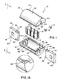
- a fuse 10 includes insulative housing pieces 12, 14 made of plastics material, terminals 16 made of conducting material, fusible elements 18 made of conducting material, and plugs 19.
- the insulative housing pieces 12, 14 have tubular portions 20 and end portions 22.
- the end portions 22 have surfaces defining slots 24 and fill holes 26 after the pieces 12, 14 have been joined together.
- the slots 24 extend between and are defined by wall extensions 28, which extend into the interior of the housing.
- the long axis of each slot 24 (in the face of each end portion 22) is perpendicular to the seam formed when the two housing pieces 12,14 are joined.
- the terminals 16 include external portions 30, internal portions 32, and middle portions 34 (within slots 24).
- the external portions 30 have holes 60.
- the fusible elements 18 are attached to opposite surfaces 36 of the internal portions 32.
- the fusible elements 18 have current limiting notch sections 33 defined by rows of holes and are generally corrugated to provide a relatively larger number of notch sections 33 for a given length of housing than would be permitted if the fusible elements 18 were straight.
- each terminal 16 is larger than the slots 24, and the middle portion 34 is essentially the same size as the slot. This ensures that, after housing pieces 12, 14 have been joined, each terminal 16 is retained and anchored in the housing by interference between its internal portion 32 and the walls defining slot 24. Wall extensions 28 (Fig. 3) make the slots deeper and thereby increase the support of terminals 16.
- fusible elements 18 are attached to surfaces 36 by resistance (spot or continuous) welding or ultrasonic welding.
- the subassembly of terminals 16 and attached fusible elements 18 is then inserted in housing piece 14. Housing piece 12 is placed in position, and pieces 12, 14 are joined to each other.
- housing pieces 12,14 are made of thermoplastic material, they can be joined together by ultrasonic welding. As shown in Fig. 1, housing pieces 12, 14 are identical and include mating edge surfaces 82. When housing pieces 12, 14 are joined, projections 84 on one piece coincide with flat portions of edge surface 82 on the other piece. Alternatively, all projections 84 could be on one piece, and all flat portions could be on the other. Triangular projections 84 direct the ultrasonic welding energy and increase the efficiency of the welding process. When using ultrasonic welding to join housing pieces, it is preferred that the fusible elements be aligned with the direction of vibration (as in Fig. 1) and not perpendicular to it (as in the Fig. 4 embodiment discussed below).
- Fig. 6 shows a different joint configuration, a shear joint, which can be used along an edge and is particularly preferred for semi-crystalline material in order to obtain good joint strength.
- Upper piece 100 has right angle portion 102 including lower surface 104, vertical surface 106, and uppersurface 108.
- the mating portion of lower piece 110 has similar right angle portion including lower surface 112, vertical surface 114, and upper surface 116.
- the other sides of pieces 100, 110 have the same mating configurations; piece 100 could have the projection defined by surfaces 104, 106 on the inside (as it is shown on Fig.
- the overall wall thickness is about 3.3mm (0.13") thick, and there is between 0.3mm (0.012") and 0.4mm (0.016") interference for the vertical surfaces used to permit ultrasonic welding.
- lower piece 110 is fixed, and upper piece 100 is moved toward it and vibrated at 20 KHz.
- the material of the interfering vertical surfaces melts due to friction as the two are brought together, resulting in a shear joint that has good bond strength.
- Energy directing triangular projections would still be used at the ends of the tubes, owing to geometry limitations.
- the thermoplastic material has the capability to be melted and reformed while retaining its properties when cooled below its melt point; this is desirable to permit joinder of preformed housing pieces by welding and to avoid the use of adhesives.
- the material should also have a sufficiently high continuous use temperature so as to maintain structural integrity at elevated temperatures resulting from heating when operating at rated current conditions.
- the continuous use temperature (UL746C, 100,000 hour test) is greater than 110 °C (most preferably greater than 120 °C).
- Fillers are preferably added to the thermoplastic resins to reduce the cost of the material and to improve the mechanical properties of the plastic by forming a support matrix within the plastic. Fillers tend to increase the continuous use temperature of the thermoplastic material, thereby providing improved structural integrity at elevated temperatures.
- Suitable filler materials include fiber glass, calcium carbonate, carbon fiber, cellulose, and graphite fiber.
- thermoplastic materials with a continuous use temperature above 110°C and a fitter concentration between 20% and 40% (most preferably between 30% and 35%) provide necessary strength at elevated temperature while still permitting processing by ultrasonic welding.
- the thermoplastic material also preferably includes a flame retardant, is nontoxic (not give off toxins when it melts), and has high dielectric strength (above 400 volts/mil).
- thermoplastic material is glass reinforced polyphthalamide semicrystalline resin containing 33% glass filler available under the Amodel AF-1133 VO trade designation from Amoco Performance Products, Inc., Atlanta, GA.
- This material includes a flame retardant and presently has a provisional rating by Underwriters Laboratories Inc. for a continuous use temperature of 115 °C for electrical (the relevant continuous use temperature for the invention) and 130 °C for mechanical without impact, per UL746C.
- suitable materials include a highly crystalline Nylon 4.6, having 30% glass filler, and available from DSM Corp. under the Stanyl trade designation; polyphenylene sulfide having 30% glass filler and available from Phillips Corp. under the Ryton trade designation; and glass-filled liquid crystal polymers such as Xydar from Amoco, Supec from General Electric, and Vectra from Hoechst Celanese.
- thermoset materials that are joined together by adhesive or solvent bonding.
- terminals 16 and fusible element 18 are advantageously easily installed at the same time that the housing is formed from two pieces, and the terminals are anchored without crimping, staking, welding, pinning or other techniques, owing to the fact that terminal slots 24 are defined by facing housing pieces 12,14 and are smaller than interior portions 32.
- Another technique for joining housing pieces 12, 14 together is by adhesive bonding, e.g., when the material is a thermoset plastic or also when it is a thermoplastic.
- the void space resulting in the housing is filled with a granular arc-quenching fill material (e.g., 50/70 or 40/60 quartz; not shown) through fill holes 26 located in the end portions of the housing.
- a granular arc-quenching fill material e.g., 50/70 or 40/60 quartz; not shown
- fill holes 26 located in the end portions of the housing.
- solid fill as with sodium silicate
- fill already introduced into the housing is soaked with a liquid bath of the sodium silicate, which wicks through the sand and is then cured.
- Solid fi is preferably employed forther- moplastic materials to provide added strength to the fuse at elevated temperatures.
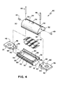
- fuse 40 includes insulative housing pieces 42, 44 made of plastic, terminals 46 made of conducting material, pins 48 made of conducting material, fusible elements 18 made of conducting material, and plugs 49.
- Insulative housing pieces 42, 44 have tubular portions 50 and end portions 52.
- a tubular portion 50 has a hole 54 therethrough for receiving a blown-fuse indicator (not shown).
- End portions 52 include pin holes 56 and recesses that define slots 58 after pieces 50 have been joined together. The long axis of each slot 58 (in the face of end portion 52) is parallel to the seam formed when the two housing pieces 42, 44 are joined.
- Terminals 46 include external portions 62, internal portions 62, and middle portions 64 (within slots 58).
- Middle portions 64 include pin holes 66. Fusible elements 18 are attached to opposite surfaces 68 of internal portions 62.
- End portions 52 also have fill holes 53 therethrough for receiving fill material; holes 53 are sealed with preformed metal plugs 49 or a nonconductive potting plug.
- Housing pieces 42, 44 are joined via mating grooves and projections.
- Housing pieces 42, 44 are identical, each having a first side edge 86 with a projection 88 and a second side edge 90 with a groove 92 arranged so that the projection 88 of the housing piece 42 fits into the groove 92 of housing piece 44 and the projection on housing piece 44 fits into the groove on housing piece 42.
- a groove 92 could be provided on both sides of one housing piece (which would then be considered the female piece) and a projection 88 could be provided on both sides of the other housing piece (which would then be considered the male piece).
- Housing pieces 42, 44 can be bonded together by ultrasonic welding, if made of thermoplastic material, or by adhesive bonding.
- Terminals 46 are retained in the housing by pins 48 passing through pin holes 56 in the housing and pin holes 66 in the terminals. These pins also can be used to make an electrical connection to an indicator or sensor at the surface of the housing.
- the housing is filled with an arc-quenching fill (not shown) through fill holes 54 located in the tubular portions of the housing.
- the fill can be granular or solid, as already described. Fill holes 54 are then sealed with plugs 49.
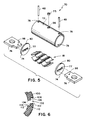
- fuse 70 includes tubular housing 72 made of insulative material (e.g., a thermoset), end blocks 74 made of either conducting or insulative material, terminals 76 made of conducting material, pins 48 made of conducting material, fusible elements 18 made of conducting material, and plug 75.
- Tubular housing 72 has pin holes 78 (near the ends) and fill hole 96.
- Each end block 74 has a respective terminal slot 77 and a single pin hole 80 that extends radially through the end block, perpendicular to the long axis of slot 77.
- Terminals 76 and end blocks 74 are retained in tubular housing 72 by pins 48 passing through pin holes 78, 80 in end blocks 74, and pin holes 98 in terminals 76.
- the housing is filled with an arc-quenching fill (not shown) through fill hole 96 located in tubular housing 72.
- the fill can be granular or solid, as already described.
- Fill hole 96 is then sealed with plug 75.
- tubular housing 72 can alternatively be made of glass melamine glass.
- End blocks 74 can be made of plastic.
- fuse casing 120 is used with terminals similar to those shown in Fig. 1. Instead of using wall extensions 28 to define slots 24 and support the terminals (as in the Fig. 1 embodiment), fuse casing 120 employs inner walls 122, which are spaced from associated end walls 124. Also, housing pieces 126, 128 of fuse casing 120 are joined by a shear joint at the seam along tubularwalls 130 and end walls 124, as shown in detail in Fig. 10.
- Housing pieces 126 and 128 are injection molded from glass reinforced polyphthalamide semicrystalline resin containing 33% glass filler available under the Amodel AF-1133 VO trade designation from Amoco Performance Products, Inc., Atlanta, GA.
- Inner walls 122 of housing pieces 126 and 128 do not extend fully across the tubular region in the housing, but instead extend from the tubular walls 130 about two- thirds of the way toward the plane at the seam between pieces 126, 128.
- a fusible element (not shown in Fig. 7) is contained within cavity space 132 between inner walls 122.
- Transverse ribs 134 connect inner walls 122 to respective end walls 124.
- End walls 124 have slots 136 for receiving terminals (e.g., terminal 140 shown in Fig.
- inner walls 122 have recessed surfaces 138 and side surfaces 139 aligned with slots 136 to define passages for receiving the fuse terminals.
- terminal 140 has enlarged inner portion 142 that is larger across than the distance between opposed surfaces 138 of pieces 126 and 128, causing terminal 140 to be retained therein.
- Terminal 140 is supported by the surface of end wall 124 defining slot 136 and surfaces 138, 139 of inner walls 122; the distance between innerwall 122 and end wall 124 provides stability.
- End wall 124 and tubular wall 130 are 2.3mm (0.091"- )thick; inner walls 122 are 1.5mm (0.060")thick. This arrangement provides good support for the terminals and avoids distortion problems that can occur when molded plastic pieces have large regions of plastic.
- seam portion 144 on housing piece 126 has lower surface 148 (1.3 mm (0.050") wide), vertical surface 150 (2.3 mm (0.091”) high), and upper surface 152 (1.4 mm (0.054") wide).
- Mating seam portion 146 of lower piece 128 has lower surface 154 (1.0 mm (0.040") wide), major vertical surface 156 (1.8 mm (0.071") high), interfering shelf surface 158 (0.4 mm (0.014") wide), further short vertical surface 160 (0.5 mm (0.020”) high) and upper surface 162 (1.3 mm (0.050”) wide).
- Piece 126 is considered a male piece, while piece 128 is considered a female piece.
- the overall wall thickness is about 2.3 mm (0.091”) thick, except at the seam, where the wall is about 2.6 mm (0.104") thick.
- housing piece 128 There is 0.3 mm (0.010") interference between major vertical surface 156 of housing piece 128 and vertical surface 150 of housing piece 126.
- lower piece 128 is fixed, and upper piece 126 is moved towards it and vibrated at 20 kHz.
- the material of the interfering vertical surfaces melts due to friction as the two are brought together, resulting in a shear joint that has good bond strength.
- a particular fuse can include one or a plurality of fusible elements 18.
- the terminals of the Fig. 5 embodiment could be insert molded in the end blocks.
- other welding techniques can be employed; e.g., the mating faces might be heated by a source of heat (as opposed to friction) and then joined together.
- solvent bonding could be used to join together two housing pieces.
- other cylindrical shapes such as those having square or hexagon cross sections can be used.
Landscapes
- Fuses (AREA)
Abstract
Description
- The invention relates to current limiting fuses.
- Current limiting fuses typically have one or more fusible elements connecting two conducting terminals within an insulative housing.
- One type of fuse construction employs a housing made of a tubular casing of melamine glass, cardboard, or thermoset polymer resins in a matrix with glass or papers. The ends of the tubes are typically closed with end caps, which go around the ends of the tube, or end blocks of brass or copper, which are inside of the tube at the ends. When end blocks are employed, there often are terminal blades that are located on the outer surfaces of the end blocks (being either integral with or attached such as by welding or brazing to the end blocks), and fusible elements are connected, e.g. by welding, in grooves to the inside surfaces of the end blocks.
- US Patent No. US-A-O 973 250 (Barricklow) describes a different type of fuse construction in which the insulative housing is made of two pieces that have been bolted together.
- In one aspect, the invention features, in general, making an insulative fuse housing by ultrasonically welding together housing pieces made of thermoplastic material. The thermoplastic material has a continuous use temperature greater than 110°C (most preferably greater than 120°C) to provide structural integrity at elevated temperatures to which fuses are subjected in use. The material includes filler (e.g., fiberglass) in a range between 20% and 40% (most preferably between 30% and 35%) to have enough filler to provide a significant increase of the continuous use temperature of the thermoplastic material but to not have so much filleras to prevent bonding by ultrasonic welding. Suitable thermoplastic materials include highly crystalline Nylon 4.6, polyphthalamide, polyphenylene sulfide, and liquid crystal polymer.
- In another aspect, the invention features, in general, a fuse including a fuse housing made from two or more housing pieces made from molded thermoplastic material. The housing has end walls with openings through which terminals pass. The housing also has inner walls that are integral with and spaced from respective end walls and have surfaces that define passages that are aligned with the openings. The terminals are supported by the end walls around the openings and by the surfaces of the inner walls defining the passages. This arrangement provides good support for the terminals without relying on a concentrated mass of thermoplastic material adjacent to the end walls.
- In preferred embodiments, there are two, generally coplanar, inner walls associated with each end wall; one inner wall is on one housing piece; the other inner wall is on another housing piece; there is a space between the inner walls, and the inner walls each have a recess that receives a portion of the terminal. The inner walls are thinner than the end walls, and transverse ribs join each inner wall with its respective end wall on both sides of the terminal. The housing pieces are joined to each other at a shear joint formed between mating seam portions having a stepped configuration. The housing pieces have interfering portions at the mating seam portions and are joined together by ultrasonic welding.
- In another aspect, the invention features, in general, a fuse which includes an insulative housing that has a tubular portion and two end portions that are located at the ends of the tubular portion and have slots through which terminals pass. The housing is made from two plastic housing pieces that have been joined together. The terminals have portions inside and outside of the housing, and a fusible element located inside the housing has ends connected to each of the terminals. This approach permits reducing the number of parts and simplifies the assembly and manufacture procedure.
- In preferred embodiments, the tubular portion of the housing is cylindrical, and the end portions are circular. The two housing pieces can be composed of male and female parts, or they could be composed of identical parts. Each of the slots is defined by portions on both of the housing pieces. The end portions can have wall extensions that extend perpendicularly from the end portions into the housing, partially define the slots, and strengthen the support of the terminals. The slots can be perpendicular to or aligned with the seam formed by joinder of the two housing pieces. The terminals can have internal and external portions that are wider than middle portions that are situated within the slots, thereby retaining the terminals in the slots by interference with the housing. The fusible element can be attached to the terminals by resistance welding or ultrasonic welding. The fusible element is preferably corrugated, and multiple fusible elements can be used. The voids in the housing are preferably occupied by arc-quenching fill material introduced into the housing via fi holes that are sealed with preformed metal plugs or nonconductive potting plugs after filling. The fill can be a solid fill.
- In another aspect, the invention features, in general, a fuse in which terminals are retained in respective slots through end portions of a tubular insulative housing by respective pins that each pass through a hole in the terminal and holes on both sides of the terminal in the end portions of the housing.
- In a preferred embodiment, the housing is made of a tubular member with two ends and two slotted end blocks located at each of the two ends of the tubular member. Each pin extends through holes at the ends of the tubular member and holes in the end blocks.
- The invention will now be described by way of example with reference to the accompanying drawings, throughout which like parts are referred to by like references, and in which:
- Fig. 1 is an exploded perspective view of a fuse according to an embodiment of the invention;
- Fig. 1A is an enlarged view of the portion marked 1Aon Fig. 1;
- Fig. 2 is a sectional view, taken at 2-2 of Fig. 1, of the fuse shown in Fig. 1;
- Fig. 3 is a plan view, partially in section, of components of the fuse shown in Fig. 1, during assembly;
- Fig. 4 is an exploded perspective view of a fuse according to an alternative embodiment of the invention;
- Fig. 5 is an exploded perspective view of a fuse according to another alternative embodiment of the invention;
- Fig. 6 is a partial sectional view showing thejunc- tion of housing pieces of the fuse shown in Fig. 1;
- Fig. 7 is an exploded perspective view of a fuse casing of an alternative embodiment of the invention;
- Fig. 8 is a sectional view, taken at 8-8 of Fig. 7, of the fuse casing shown with a portion of a terminal;
- Fig. 9 is a plan view of a housing piece of the fuse casing shown in Fig. 7; and
- Fig. 10 is a partial sectional view showing the junction of housing pieces of the fuse shown in Fig. 7.
- Referring to Figs. 1, 1A, 2 and 3, a
fuse 10 includesinsulative housing pieces terminals 16 made of conducting material,fusible elements 18 made of conducting material, andplugs 19. Theinsulative housing pieces tubular portions 20 andend portions 22. Theend portions 22 havesurfaces defining slots 24 and fillholes 26 after thepieces slots 24 extend between and are defined bywall extensions 28, which extend into the interior of the housing. The long axis of each slot 24 (in the face of each end portion 22) is perpendicular to the seam formed when the twohousing pieces terminals 16 includeexternal portions 30,internal portions 32, and middle portions 34 (within slots 24). Theexternal portions 30 haveholes 60. Thefusible elements 18 are attached toopposite surfaces 36 of theinternal portions 32. Thefusible elements 18 have current limitingnotch sections 33 defined by rows of holes and are generally corrugated to provide a relatively larger number ofnotch sections 33 for a given length of housing than would be permitted if thefusible elements 18 were straight. - As shown in Fig. 2, the
external portion 30 andinternal portion 32 of eachterminal 16 are larger than theslots 24, and themiddle portion 34 is essentially the same size as the slot. This ensures that, afterhousing pieces terminal 16 is retained and anchored in the housing by interference between itsinternal portion 32 and thewalls defining slot 24. Wall extensions 28 (Fig. 3) make the slots deeper and thereby increase the support ofterminals 16. - In manufacture, the ends of
fusible elements 18 are attached tosurfaces 36 by resistance (spot or continuous) welding or ultrasonic welding. The subassembly ofterminals 16 and attachedfusible elements 18 is then inserted inhousing piece 14.Housing piece 12 is placed in position, andpieces - When
housing pieces housing pieces housing pieces projections 84 on one piece coincide with flat portions ofedge surface 82 on the other piece. Alternatively, allprojections 84 could be on one piece, and all flat portions could be on the other.Triangular projections 84 direct the ultrasonic welding energy and increase the efficiency of the welding process. When using ultrasonic welding to join housing pieces, it is preferred that the fusible elements be aligned with the direction of vibration (as in Fig. 1) and not perpendicular to it (as in the Fig. 4 embodiment discussed below). - Fig. 6 shows a different joint configuration, a shear joint, which can be used along an edge and is particularly preferred for semi-crystalline material in order to obtain good joint strength.
Upper piece 100 hasright angle portion 102 includinglower surface 104,vertical surface 106, anduppersurface 108. The mating portion of lower piece 110 has similar right angle portion includinglower surface 112, vertical surface 114, and upper surface 116. The other sides ofpieces 100, 110 have the same mating configurations;piece 100 could have the projection defined bysurfaces surfaces upper piece 100 is moved toward it and vibrated at 20 KHz. The material of the interfering vertical surfaces melts due to friction as the two are brought together, resulting in a shear joint that has good bond strength. Energy directing triangular projections would still be used at the ends of the tubes, owing to geometry limitations. - The thermoplastic material has the capability to be melted and reformed while retaining its properties when cooled below its melt point; this is desirable to permit joinder of preformed housing pieces by welding and to avoid the use of adhesives. The material should also have a sufficiently high continuous use temperature so as to maintain structural integrity at elevated temperatures resulting from heating when operating at rated current conditions. Preferably the continuous use temperature (UL746C, 100,000 hour test) is greater than 110 °C (most preferably greater than 120 °C). Fillers are preferably added to the thermoplastic resins to reduce the cost of the material and to improve the mechanical properties of the plastic by forming a support matrix within the plastic. Fillers tend to increase the continuous use temperature of the thermoplastic material, thereby providing improved structural integrity at elevated temperatures. However, depending on the resin and filler material, increasing filler concentration beyond a certain amount tends to reduce the strength; also, increasing the concentration beyond a certain amount may tend to negatively affect the ability to create strong bonds using ultrasonic welding. It accordingly is desirable to increase the continuous use temperature as much as possible while still achieving good bond strength using ultrasonic welding. Suitable filler materials include fiber glass, calcium carbonate, carbon fiber, cellulose, and graphite fiber. In general, thermoplastic materials with a continuous use temperature above 110°C and a fitter concentration between 20% and 40% (most preferably between 30% and 35%) provide necessary strength at elevated temperature while still permitting processing by ultrasonic welding. The thermoplastic material also preferably includes a flame retardant, is nontoxic (not give off toxins when it melts), and has high dielectric strength (above 400 volts/mil).
- A suitable material for the thermoplastic material is glass reinforced polyphthalamide semicrystalline resin containing 33% glass filler available under the Amodel AF-1133 VO trade designation from Amoco Performance Products, Inc., Atlanta, GA. This material includes a flame retardant and presently has a provisional rating by Underwriters Laboratories Inc. for a continuous use temperature of 115 °C for electrical (the relevant continuous use temperature for the invention) and 130 °C for mechanical without impact, per UL746C.
- Other suitable materials include a highly crystalline Nylon 4.6, having 30% glass filler, and available from DSM Corp. under the Stanyl trade designation; polyphenylene sulfide having 30% glass filler and available from Phillips Corp. under the Ryton trade designation; and glass-filled liquid crystal polymers such as Xydar from Amoco, Supec from General Electric, and Vectra from Hoechst Celanese.
- Also, some aspect of the invention can be used with thermoset materials that are joined together by adhesive or solvent bonding.
- The use of
identical housing pieces terminals 16 andfusible element 18 is advantageously easily installed at the same time that the housing is formed from two pieces, and the terminals are anchored without crimping, staking, welding, pinning or other techniques, owing to the fact thatterminal slots 24 are defined by facinghousing pieces interior portions 32. - Another technique for joining
housing pieces - After bonding
pieces - Referring to Fig. 4, fuse 40 includes
insulative housing pieces terminals 46 made of conducting material, pins 48 made of conducting material,fusible elements 18 made of conducting material, and plugs 49.Insulative housing pieces tubular portions 50 andend portions 52. Atubular portion 50 has ahole 54 therethrough for receiving a blown-fuse indicator (not shown).End portions 52 include pin holes 56 and recesses that defineslots 58 afterpieces 50 have been joined together. The long axis of each slot 58 (in the face of end portion 52) is parallel to the seam formed when the twohousing pieces Terminals 46 includeexternal portions 62,internal portions 62, and middle portions 64 (within slots 58).Middle portions 64 include pin holes 66.Fusible elements 18 are attached toopposite surfaces 68 ofinternal portions 62.End portions 52 also have fill holes 53 therethrough for receiving fill material; holes 53 are sealed with preformed metal plugs 49 or a nonconductive potting plug. -
Housing pieces Housing pieces first side edge 86 with aprojection 88 and asecond side edge 90 with agroove 92 arranged so that theprojection 88 of thehousing piece 42 fits into thegroove 92 ofhousing piece 44 and the projection onhousing piece 44 fits into the groove onhousing piece 42. Alternatively, agroove 92 could be provided on both sides of one housing piece (which would then be considered the female piece) and aprojection 88 could be provided on both sides of the other housing piece (which would then be considered the male piece).Housing pieces -
Terminals 46 are retained in the housing bypins 48 passing through pin holes 56 in the housing and pinholes 66 in the terminals. These pins also can be used to make an electrical connection to an indicator or sensor at the surface of the housing. - The housing is filled with an arc-quenching fill (not shown) through fill holes 54 located in the tubular portions of the housing. The fill can be granular or solid, as already described. Fill holes 54 are then sealed with
plugs 49. - Referring to Fig. 5, fuse 70 includes
tubular housing 72 made of insulative material (e.g., a thermoset), end blocks 74 made of either conducting or insulative material,terminals 76 made of conducting material, pins 48 made of conducting material,fusible elements 18 made of conducting material, and plug 75.Tubular housing 72 has pin holes 78 (near the ends) and fillhole 96. Eachend block 74 has a respectiveterminal slot 77 and asingle pin hole 80 that extends radially through the end block, perpendicular to the long axis ofslot 77. -
Terminals 76 and end blocks 74 are retained intubular housing 72 bypins 48 passing through pin holes 78, 80 in end blocks 74, and pinholes 98 interminals 76. - The housing is filled with an arc-quenching fill (not shown) through
fill hole 96 located intubular housing 72. The fill can be granular or solid, as already described. Fillhole 96 is then sealed withplug 75. - In the embodiment shown in Fig. 5,
tubular housing 72 can alternatively be made of glass melamine glass. End blocks 74 can be made of plastic. - Referring to Figs. 7 - 10,
fuse casing 120 is used with terminals similar to those shown in Fig. 1. Instead of usingwall extensions 28 to defineslots 24 and support the terminals (as in the Fig. 1 embodiment),fuse casing 120 employsinner walls 122, which are spaced from associatedend walls 124. Also,housing pieces fuse casing 120 are joined by a shear joint at the seam alongtubularwalls 130 and endwalls 124, as shown in detail in Fig. 10. -
Housing pieces Inner walls 122 ofhousing pieces tubular walls 130 about two- thirds of the way toward the plane at the seam betweenpieces cavity space 132 betweeninner walls 122.Transverse ribs 134 connectinner walls 122 torespective end walls 124.End walls 124 haveslots 136 for receiving terminals (e.g., terminal 140 shown in Fig. 8), andinner walls 122 have recessedsurfaces 138 andside surfaces 139 aligned withslots 136 to define passages for receiving the fuse terminals. As shown in Fig. 8,terminal 140 has enlargedinner portion 142 that is larger across than the distance betweenopposed surfaces 138 ofpieces Terminal 140 is supported by the surface ofend wall 124 definingslot 136 and surfaces 138, 139 ofinner walls 122; the distance betweeninnerwall 122 andend wall 124 provides stability.End wall 124 andtubular wall 130 are 2.3mm (0.091"- )thick;inner walls 122 are 1.5mm (0.060")thick. This arrangement provides good support for the terminals and avoids distortion problems that can occur when molded plastic pieces have large regions of plastic. - Referring to Fig. 10,
pieces mating seam portions Seam portion 144 onhousing piece 126 has lower surface 148 (1.3 mm (0.050") wide), vertical surface 150 (2.3 mm (0.091") high), and upper surface 152 (1.4 mm (0.054") wide).Mating seam portion 146 oflower piece 128 has lower surface 154 (1.0 mm (0.040") wide), major vertical surface 156 (1.8 mm (0.071") high), interfering shelf surface 158 (0.4 mm (0.014") wide), further short vertical surface 160 (0.5 mm (0.020") high) and upper surface 162 (1.3 mm (0.050") wide).Piece 126 is considered a male piece, whilepiece 128 is considered a female piece. The overall wall thickness is about 2.3 mm (0.091") thick, except at the seam, where the wall is about 2.6 mm (0.104") thick. There is a 0.1 mm (0.004") clearance between shortvertical surface 160 ofpiece 128 andvertical surface 150 ofpiece 126. There is 0.3 mm (0.010") interference between majorvertical surface 156 ofhousing piece 128 andvertical surface 150 ofhousing piece 126. During ultrasonic welding,lower piece 128 is fixed, andupper piece 126 is moved towards it and vibrated at 20 kHz. The material of the interfering vertical surfaces melts due to friction as the two are brought together, resulting in a shear joint that has good bond strength. - Other embodiments of the invention are within the scope of the following claims. For example, a particular fuse can include one or a plurality of
fusible elements 18. Also, the terminals of the Fig. 5 embodiment could be insert molded in the end blocks. Also, other welding techniques can be employed; e.g., the mating faces might be heated by a source of heat (as opposed to friction) and then joined together. Also, solvent bonding could be used to join together two housing pieces. In addition to cylindrical fuse housings, other cylindrical shapes such as those having square or hexagon cross sections can be used.
Claims (38)
Applications Claiming Priority (2)
| Application Number | Priority Date | Filing Date | Title |
|---|---|---|---|
| US52355 | 1993-04-23 | ||
| US08/052,355 US5357234A (en) | 1993-04-23 | 1993-04-23 | Current limiting fuse |
Publications (2)
| Publication Number | Publication Date |
|---|---|
| EP0621621A2 true EP0621621A2 (en) | 1994-10-26 |
| EP0621621A3 EP0621621A3 (en) | 1995-11-08 |
Family
ID=21977075
Family Applications (1)
| Application Number | Title | Priority Date | Filing Date |
|---|---|---|---|
| EP94302904A Withdrawn EP0621621A3 (en) | 1993-04-23 | 1994-04-22 | Current limiting fuses. |
Country Status (5)
| Country | Link |
|---|---|
| US (2) | US5357234A (en) |
| EP (1) | EP0621621A3 (en) |
| JP (1) | JPH0757613A (en) |
| BR (1) | BR9400989A (en) |
| CA (1) | CA2121953A1 (en) |
Cited By (7)
| Publication number | Priority date | Publication date | Assignee | Title |
|---|---|---|---|---|
| WO2000060629A1 (en) * | 1999-04-02 | 2000-10-12 | Littelfuse, Inc. | Fuse having improved fuse housing |
| WO2004105069A1 (en) | 2003-05-26 | 2004-12-02 | Abb Sp. Z O. O. | A high-voltage thick-film high rupturing capacity substrate fuse |
| EP2087499A1 (en) * | 2006-10-30 | 2009-08-12 | Valeo Securité Habitacle | Method for production of a low current switch module and device obtained by said method |
| WO2012025853A1 (en) | 2010-08-23 | 2012-03-01 | Brusa Elektronik Ag | Electrical fuse |
| EP3511971A1 (en) * | 2018-01-05 | 2019-07-17 | Littelfuse, Inc. | Multi-part symmetrical fuse assembly |
| CN110678953A (en) * | 2017-05-31 | 2020-01-10 | 三菱电机株式会社 | Current interruption element and ozone generator |
| WO2025031526A1 (en) * | 2023-08-04 | 2025-02-13 | Saltek S.R.O. | Electrical fuse |
Families Citing this family (81)
| Publication number | Priority date | Publication date | Assignee | Title |
|---|---|---|---|---|
| US5604475A (en) * | 1994-04-07 | 1997-02-18 | S&C Electric Company | Current-limiting fuse and housing arrangement |
| US5668521A (en) * | 1995-03-22 | 1997-09-16 | Littelfuse, Inc. | Three piece female blade fuse assembly having fuse link terminal with a clip receiving portion |
| US5581225A (en) * | 1995-04-20 | 1996-12-03 | Littelfuse, Inc. | One-piece female blade fuse with housing |
| US5736918A (en) * | 1996-06-27 | 1998-04-07 | Cooper Industries, Inc. | Knife blade fuse having an electrically insulative element over an end cap and plastic rivet to plug fill hole |
| US5741217A (en) * | 1996-07-30 | 1998-04-21 | Gero; Jeffrey | Biofeedback apparatus |
| US5841337A (en) * | 1997-01-17 | 1998-11-24 | Cooper Technologies Company | Touch safe fuse module and holder |
| US5929740A (en) * | 1997-10-20 | 1999-07-27 | Littelfuse, Inc. | One-piece female blade fuse with housing and improvements thereof |
| US5886612A (en) * | 1997-10-20 | 1999-03-23 | Littelfuse, Inc. | Female fuse housing |
| USD407693S (en) | 1998-02-17 | 1999-04-06 | Cooper Industries, Inc. | Fuse holder |
| US6054915A (en) * | 1998-02-17 | 2000-04-25 | Cooper Industries, Inc. | Compact touchsafe fuseholder with removable fuse carrier |
| US6157287A (en) * | 1999-03-03 | 2000-12-05 | Cooper Technologies Company | Touch safe fuse module and holder |
| US6256183B1 (en) | 1999-09-09 | 2001-07-03 | Ferraz Shawmut Inc. | Time delay fuse with mechanical overload device and indicator actuator |
| US6228508B1 (en) † | 2000-02-07 | 2001-05-08 | Spraying Systems Co. | Process for preparing a metal body having a hermetic seal |
| GB2376138A (en) * | 2001-05-29 | 2002-12-04 | Cooper Technologies Co | Magnetically actuated fuse indicator |
| USD492261S1 (en) | 2001-07-20 | 2004-06-29 | Matsushita Electric Industrial Co., Ltd. | Fuse |
| USD482004S1 (en) | 2001-07-20 | 2003-11-11 | Matsushita Electric Industrial Co., Ltd. | Fuse |
| US7570148B2 (en) * | 2002-01-10 | 2009-08-04 | Cooper Technologies Company | Low resistance polymer matrix fuse apparatus and method |
| JP2003317589A (en) * | 2002-04-24 | 2003-11-07 | Nec Schott Components Corp | Thermosensitive pellet type thermal fuse |
| USD489689S1 (en) | 2002-05-30 | 2004-05-11 | Matsushita Electric Industrial Co., Ltd. | Fuse |
| USD502688S1 (en) * | 2002-05-30 | 2005-03-08 | Matsushita Electric Industrial Co., Ltd. | Fuse |
| USD479827S1 (en) | 2002-05-30 | 2003-09-23 | Matsushita Electric Industrial Co., Ltd. | Fuse |
| USD493774S1 (en) | 2002-05-30 | 2004-08-03 | Matsushita Electric Industrial Co., Ltd. | Fuse |
| JP4192266B2 (en) * | 2002-09-25 | 2008-12-10 | 太平洋精工株式会社 | Current limiting fuse |
| JP2005093193A (en) * | 2003-09-17 | 2005-04-07 | Anzen Dengu Kk | Resistor equipped with smokeless temperature fuse |
| JP4471203B2 (en) * | 2003-10-28 | 2010-06-02 | エヌイーシー ショット コンポーネンツ株式会社 | Temperature-sensitive pellet type temperature fuse and method of manufacturing temperature-sensitive pellet |
| CN1957434B (en) | 2004-03-05 | 2010-05-12 | 力特保险丝有限公司 | Blade type fuse for automobile |
| EP1797576A4 (en) * | 2004-09-15 | 2008-12-10 | Littelfuse Inc | High voltage/high current fuse |
| JP4375738B2 (en) | 2004-09-17 | 2009-12-02 | エヌイーシー ショット コンポーネンツ株式会社 | Temperature-sensitive pellet type thermal fuse |
| JP4521725B2 (en) * | 2005-03-17 | 2010-08-11 | エヌイーシー ショット コンポーネンツ株式会社 | Thermal pellet type thermal fuse |
| JP4583228B2 (en) * | 2005-04-18 | 2010-11-17 | エヌイーシー ショット コンポーネンツ株式会社 | Thermal pellet type thermal fuse |
| US20080100412A1 (en) * | 2006-10-06 | 2008-05-01 | Han-Ming Lee | Insulated shockproof fuse |
| USD559203S1 (en) | 2006-11-14 | 2008-01-08 | Littelfuse, Inc. | Indicator for a fuse |
| US7843307B2 (en) * | 2007-10-05 | 2010-11-30 | Nec Schott Components Corporation | Thermal fuse employing thermosensitive pellet |
| USD575746S1 (en) | 2008-01-14 | 2008-08-26 | Littelfuse, Inc. | Blade fuse and fuse element therefore |
| USD575745S1 (en) | 2008-01-14 | 2008-08-26 | Littelfuse, Inc. | Blade fuse and fuse element therefore |
| US8077007B2 (en) | 2008-01-14 | 2011-12-13 | Littlelfuse, Inc. | Blade fuse |
| JP4998890B2 (en) * | 2008-02-12 | 2012-08-15 | 国立大学法人埼玉大学 | Fuse element and fuse |
| US8339235B2 (en) * | 2008-08-06 | 2012-12-25 | Beckert James J | Housing securing apparatus for electrical components, especially fuses |
| JP5130232B2 (en) * | 2009-01-21 | 2013-01-30 | デクセリアルズ株式会社 | Protective element |
| JP5130233B2 (en) * | 2009-01-21 | 2013-01-30 | デクセリアルズ株式会社 | Protective element |
| US9196445B2 (en) * | 2011-07-05 | 2015-11-24 | Cooper Technologies Company | Electric fuse with torque restricting terminals |
| DE102012205021A1 (en) | 2012-03-28 | 2013-10-02 | Robert Bosch Gmbh | Cell connector for a battery system or for a battery cell of an electrical energy storage, battery and motor vehicle |
| US9281152B2 (en) | 2012-12-05 | 2016-03-08 | Eaton Corporation | Fuse with carbon fiber fusible element |
| JP5675859B2 (en) * | 2013-01-28 | 2015-02-25 | 太平洋精工株式会社 | fuse |
| JP5952751B2 (en) * | 2013-02-05 | 2016-07-13 | 太平洋精工株式会社 | Manufacturing method of fuse element |
| JP2014182952A (en) * | 2013-03-19 | 2014-09-29 | Yazaki Corp | Fusible link |
| JP2014013763A (en) * | 2013-08-22 | 2014-01-23 | Taiheiyo Seiko Kk | High voltage fuse casing and high voltage fuse using the casing |
| US9892880B2 (en) * | 2014-05-22 | 2018-02-13 | Littelfuse, Inc. | Insert for fuse housing |
| US11075048B2 (en) * | 2014-05-28 | 2021-07-27 | Eaton Intelligent Power Limited | Compact high voltage power fuse and methods of manufacture |
| US11075047B2 (en) * | 2014-05-28 | 2021-07-27 | Eaton Intelligent Power Limited | Compact high voltage power fuse and methods of manufacture |
| KR102228859B1 (en) * | 2014-09-03 | 2021-03-17 | 한국단자공업 주식회사 | High voltage fuse |
| US9761402B2 (en) | 2014-11-14 | 2017-09-12 | Littelfuse, Inc. | High-current fuse with endbell assembly |
| US10224166B2 (en) | 2014-11-14 | 2019-03-05 | Littelfuse, Inc. | High-current fuse with endbell assembly |
| JP5806774B2 (en) * | 2014-11-18 | 2015-11-10 | 太平洋精工株式会社 | Manufacturing method of high-voltage fuse and casing for high-voltage fuse |
| DE202015101840U1 (en) * | 2015-04-15 | 2015-04-30 | Inter Control Hermann Köhler Elektrik GmbH & Co. KG | Fuse component |
| JP6426056B2 (en) * | 2015-06-08 | 2018-11-21 | 豊田鉄工株式会社 | fuse |
| US10598703B2 (en) | 2015-07-20 | 2020-03-24 | Eaton Intelligent Power Limited | Electric fuse current sensing systems and monitoring methods |
| JP6554611B2 (en) * | 2015-08-31 | 2019-07-31 | ビーワイディー カンパニー リミテッドByd Company Limited | relay |
| US20170345605A1 (en) * | 2016-05-24 | 2017-11-30 | Cooper Technologies Company | Fuse element assembly and method of fabricating the same |
| US10978267B2 (en) | 2016-06-20 | 2021-04-13 | Eaton Intelligent Power Limited | High voltage power fuse including fatigue resistant fuse element and methods of making the same |
| US20180108507A1 (en) * | 2016-10-14 | 2018-04-19 | GM Global Technology Operations LLC | Fuse element and method of fabrication |
| US10325746B2 (en) | 2016-11-15 | 2019-06-18 | Littelfuse, Inc. | Ventilated fuse housing |
| US11393651B2 (en) | 2018-05-23 | 2022-07-19 | Eaton Intelligent Power Limited | Fuse with stone sand matrix reinforcement |
| US11143718B2 (en) | 2018-05-31 | 2021-10-12 | Eaton Intelligent Power Limited | Monitoring systems and methods for estimating thermal-mechanical fatigue in an electrical fuse |
| US11289298B2 (en) | 2018-05-31 | 2022-03-29 | Eaton Intelligent Power Limited | Monitoring systems and methods for estimating thermal-mechanical fatigue in an electrical fuse |
| CN209461405U (en) * | 2018-11-28 | 2019-10-01 | 库柏西安熔断器有限公司 | Fuse, vehicle circuitry for electric vehicle and electric car |
| CN209496802U (en) * | 2018-11-28 | 2019-10-15 | 库柏西安熔断器有限公司 | Fuse, vehicle circuitry for electric vehicle and electric car |
| KR102066173B1 (en) * | 2019-05-14 | 2020-01-14 | 한국단자공업 주식회사 | High voltage fuse |
| JP7433796B2 (en) * | 2019-07-24 | 2024-02-20 | デクセリアルズ株式会社 | protection element |
| JP7291394B2 (en) * | 2019-12-12 | 2023-06-15 | 太平洋精工株式会社 | fuse |
| JP7429599B2 (en) * | 2020-05-14 | 2024-02-08 | 豊田鉄工株式会社 | fuse |
| JP2022067385A (en) * | 2020-10-20 | 2022-05-06 | 株式会社日之出電機製作所 | fuse |
| JP7388725B2 (en) | 2021-02-18 | 2023-11-29 | 太平洋精工株式会社 | fuse |
| US11251009B1 (en) * | 2021-04-07 | 2022-02-15 | Littelfuse, Inc. | Fuse housing for safe outgassing |
| US11289297B1 (en) * | 2021-05-07 | 2022-03-29 | Littelfuse, Inc. | Two-piece fuse endbell with pre-cast/pre-molded alignment slots and optional interface crush ribs |
| JP7475058B2 (en) | 2021-06-17 | 2024-04-26 | 太平洋精工株式会社 | Electrical Circuit Breaker |
| US12002643B2 (en) * | 2021-11-30 | 2024-06-04 | Eaton Intelligent Power Limited | Ceramic printed fuse fabrication |
| GB2613907B (en) * | 2021-12-18 | 2024-06-26 | Eaton Intelligent Power Ltd | Lightweight electric fuse |
| JP7602270B2 (en) * | 2022-08-25 | 2024-12-18 | 太平洋精工株式会社 | fuse |
| TWI827292B (en) * | 2022-09-30 | 2023-12-21 | 功得電子工業股份有限公司 | Lightweight industrial fuse |
| CN222462803U (en) * | 2024-01-26 | 2025-02-11 | 比亚迪股份有限公司 | Housing components, fuses, circuit systems and electrical equipment |
Family Cites Families (44)
| Publication number | Priority date | Publication date | Assignee | Title |
|---|---|---|---|---|
| US973250A (en) * | 1910-02-10 | 1910-10-18 | Irvin E Barricklow | Electric fuse. |
| GB517153A (en) * | 1938-08-23 | 1940-01-22 | Gordon Spencer Marston | Improvements in electric fuses |
| US2395206A (en) * | 1943-07-17 | 1946-02-19 | Virginia Electric Mfg Corp | Molded plastic fuse construction |
| US2759065A (en) * | 1955-01-10 | 1956-08-14 | Moeller Arthur Edward | Fuse holder |
| US3005741A (en) * | 1957-09-03 | 1961-10-24 | Chase Shawmut Co | Manufacturing fuses having caps made of an elastomer |
| FR1271560A (en) * | 1959-08-01 | 1962-01-19 | ||
| US3168632A (en) * | 1961-10-31 | 1965-02-02 | Advance Transformer Co | Ballast disconnect device having a coating of flux material |
| US3418616A (en) * | 1965-03-15 | 1968-12-24 | Victor Electric Wire & Cable C | Integrated fuse and wire |
| US3394333A (en) * | 1967-08-24 | 1968-07-23 | Chase Shawmut Co | Electric fuse having stress-reducing fuse link means |
| US3491322A (en) * | 1968-09-30 | 1970-01-20 | Chase Shawmut Co | Electric multifunction fuse |
| DE6802829U (en) * | 1968-10-17 | 1969-03-06 | Lindner Gmbh | ELECTRICAL CONNECTION IN THE EVENT OF LOW VOLTAGE HIGH PERFORMANCE FUSE |
| FR1593014A (en) * | 1969-09-03 | 1970-05-25 | ||
| US3766507A (en) * | 1971-11-03 | 1973-10-16 | Chase Shawmut Co | Low-voltage fuse having molded case |
| US3914863A (en) * | 1972-05-04 | 1975-10-28 | Gerald Wiebe | Method of forming a fuse |
| DE7528023U (en) * | 1975-09-04 | 1977-02-24 | Siemens Ag, 1000 Berlin Und 8000 Muenchen | Fuse link, especially for low-voltage, high-performance fuses |
| GB1479243A (en) * | 1976-02-12 | 1977-07-06 | Welwyn Electric Ltd | Electrical resistors |
| DE7619023U1 (en) * | 1976-06-16 | 1976-10-14 | Fritz Driescher Spezialfabrik Fuer Elektrizitaetswerksbedarf, 5144 Wegberg | Double-sheathed NH fuse |
| US4290183A (en) * | 1977-02-07 | 1981-09-22 | Littelfuse, Inc. | Apparatus for making plug-in fuse assemblies |
| US4164726A (en) * | 1977-08-01 | 1979-08-14 | Weibe Gerald L | Encapsulated plug-in electrically conducting component |
| US4224592A (en) * | 1978-04-03 | 1980-09-23 | Mcgraw-Edison Company | Miniature plug-in fuse assembly and method of manufacture |
| SE446860B (en) * | 1978-08-08 | 1986-10-13 | Nitro Nobel Ab | LAGENERGISTUBIN CONSISTS OF A PLASTIC HOSE WHICH HAVE BEEN COVERED WITH POWDER FORM |
| DE2844973A1 (en) * | 1978-10-16 | 1980-04-24 | Driescher Spezialfab Fritz | High rupturing capacity fuse - with quenching sand enclosed in sleeve of specified thermoplastic resin |
| US4205431A (en) * | 1978-11-02 | 1980-06-03 | Wiebe Gerald L | Method and apparatus for making a cylindrical end-capped fuse |
| US4229403A (en) * | 1979-02-01 | 1980-10-21 | S&C Electric Company | Method of assembling a fault limiter by molding a rigid housing about a non-rigid subassembly |
| US4306213A (en) * | 1980-01-28 | 1981-12-15 | General Electric Company | Layered plastic fuse |
| US4344060A (en) * | 1980-09-19 | 1982-08-10 | Littelfuse, Inc. | Enclosed plug-in fuse assembly |
| US4503415A (en) * | 1983-06-06 | 1985-03-05 | Commercial Enclosed Fuse Co. Of Nj | Encapsulated hot spot fuse link |
| DE3342302A1 (en) * | 1983-11-23 | 1985-05-30 | Wickmann-Werke GmbH, 5810 Witten | METHOD FOR THE PRODUCTION OF A SMALL FUSE AND A SMALL FUSE |
| US4580124A (en) * | 1984-08-17 | 1986-04-01 | Littelfuse, Inc. | Plug-in fuse assembly |
| US4608548A (en) * | 1985-01-04 | 1986-08-26 | Littelfuse, Inc. | Miniature fuse |
| US4928384A (en) * | 1987-03-24 | 1990-05-29 | Cooper Industries, Inc. | Method of making a wire bonded microfuse |
| US4771260A (en) * | 1987-03-24 | 1988-09-13 | Cooper Industries, Inc. | Wire bonded microfuse and method of making |
| US4965925A (en) * | 1987-03-27 | 1990-10-30 | Monter John M | Method of making an axial miniature fuse with plastic molded body |
| DE8717736U1 (en) * | 1987-03-27 | 1989-12-21 | Cooper Industries, Inc., Houston, Tex. | Electrical fuse |
| DE8704621U1 (en) * | 1987-03-28 | 1987-07-02 | Wickmann-Werke GmbH, 5810 Witten | Electrical fuse |
| US4949062A (en) * | 1989-04-24 | 1990-08-14 | Cooper Industries, Inc. | Fuse having a non-electrically conductive end bell |
| US4972170A (en) * | 1989-04-24 | 1990-11-20 | Cooper Industries, Inc. | High speed fuse |
| US4935716A (en) * | 1989-04-24 | 1990-06-19 | Cooper Industries, Inc. | Fuse having a ball plug |
| US4951026A (en) * | 1989-04-24 | 1990-08-21 | Cooper Industries, Inc. | Weld projections on fuse terminals |
| US4949063A (en) * | 1989-04-24 | 1990-08-14 | Cooper Industries, Inc. | End closure system for high speed fuse |
| FR2679378B1 (en) * | 1991-07-15 | 1995-03-03 | Daniel Wechsler | ELECTRIC FUSE FOR HIGH CURRENTS. |
| US5194577A (en) * | 1991-12-10 | 1993-03-16 | Amoco Corporation | Composition comprising crystallizable polyamide from terephthalic acid, adipic acid, aliphatic diamine and m-xylylene diamine |
| US5294905A (en) * | 1993-04-23 | 1994-03-15 | Gould Inc. | Current limiting fuse |
| US5296832A (en) * | 1993-04-23 | 1994-03-22 | Gould Inc. | Current limiting fuse |
-
1993
- 1993-04-23 US US08/052,355 patent/US5357234A/en not_active Expired - Fee Related
-
1994
- 1994-02-01 US US08/189,925 patent/US5426411A/en not_active Expired - Fee Related
- 1994-04-20 BR BR9400989A patent/BR9400989A/en not_active Application Discontinuation
- 1994-04-22 CA CA002121953A patent/CA2121953A1/en not_active Abandoned
- 1994-04-22 EP EP94302904A patent/EP0621621A3/en not_active Withdrawn
- 1994-04-25 JP JP6086880A patent/JPH0757613A/en not_active Withdrawn
Cited By (9)
| Publication number | Priority date | Publication date | Assignee | Title |
|---|---|---|---|---|
| WO2000060629A1 (en) * | 1999-04-02 | 2000-10-12 | Littelfuse, Inc. | Fuse having improved fuse housing |
| US6577222B1 (en) | 1999-04-02 | 2003-06-10 | Littelfuse, Inc. | Fuse having improved fuse housing |
| WO2004105069A1 (en) | 2003-05-26 | 2004-12-02 | Abb Sp. Z O. O. | A high-voltage thick-film high rupturing capacity substrate fuse |
| EP2087499A1 (en) * | 2006-10-30 | 2009-08-12 | Valeo Securité Habitacle | Method for production of a low current switch module and device obtained by said method |
| WO2012025853A1 (en) | 2010-08-23 | 2012-03-01 | Brusa Elektronik Ag | Electrical fuse |
| CN110678953A (en) * | 2017-05-31 | 2020-01-10 | 三菱电机株式会社 | Current interruption element and ozone generator |
| EP3633708A4 (en) * | 2017-05-31 | 2020-06-03 | Mitsubishi Electric Corporation | CURRENT BLOCKING ELEMENT AND OZONE GENERATING DEVICE |
| EP3511971A1 (en) * | 2018-01-05 | 2019-07-17 | Littelfuse, Inc. | Multi-part symmetrical fuse assembly |
| WO2025031526A1 (en) * | 2023-08-04 | 2025-02-13 | Saltek S.R.O. | Electrical fuse |
Also Published As
| Publication number | Publication date |
|---|---|
| US5426411A (en) | 1995-06-20 |
| JPH0757613A (en) | 1995-03-03 |
| US5357234A (en) | 1994-10-18 |
| EP0621621A3 (en) | 1995-11-08 |
| CA2121953A1 (en) | 1994-10-24 |
| BR9400989A (en) | 1994-11-08 |
Similar Documents
| Publication | Publication Date | Title |
|---|---|---|
| US5426411A (en) | Current limiting fuse | |
| US5296832A (en) | Current limiting fuse | |
| EP0420413B1 (en) | Means and method of securing an insert in a shell | |
| US8950059B2 (en) | Method of manufacturing a complex fusible link | |
| US4670729A (en) | Electrical fuse | |
| US5162616A (en) | Bus bar assembly | |
| US5101187A (en) | Subminiature fuse and method of manufacturing same | |
| KR100277839B1 (en) | Connection structure of lead wire and terminal, connection method thereof and terminal | |
| US6046665A (en) | Fusible link, and link and cable assembly | |
| HU215683B (en) | Automotive high current fuse | |
| KR20170131899A (en) | Busbar assembly | |
| EP0621620B1 (en) | Current limiting fuses | |
| US5270679A (en) | Split end plate fuse assembly | |
| US4949062A (en) | Fuse having a non-electrically conductive end bell | |
| US4935716A (en) | Fuse having a ball plug | |
| JP7065950B2 (en) | Electrical connection assembly | |
| US5205977A (en) | Method of securing an insert in a shell | |
| KR102913975B1 (en) | fuse | |
| CN115188645A (en) | Fuse and electronic device | |
| CN218631889U (en) | Combined fuse | |
| JP7470998B2 (en) | Substrate surface mount fuse and method for manufacturing the same | |
| CN222015332U (en) | Controlled hot melt cutter | |
| KR100773324B1 (en) | Blade type fuse | |
| JP3503561B2 (en) | Junction box | |
| KR930004698Y1 (en) | Subminiature fuse |
Legal Events
| Date | Code | Title | Description |
|---|---|---|---|
| PUAI | Public reference made under article 153(3) epc to a published international application that has entered the european phase |
Free format text: ORIGINAL CODE: 0009012 |
|
| AK | Designated contracting states |
Kind code of ref document: A2 Designated state(s): DE DK ES FR GB IT |
|
| PUAL | Search report despatched |
Free format text: ORIGINAL CODE: 0009013 |
|
| AK | Designated contracting states |
Kind code of ref document: A3 Designated state(s): DE DK ES FR GB IT |
|
| 17P | Request for examination filed |
Effective date: 19960319 |
|
| 17Q | First examination report despatched |
Effective date: 19970314 |
|
| STAA | Information on the status of an ep patent application or granted ep patent |
Free format text: STATUS: THE APPLICATION IS DEEMED TO BE WITHDRAWN |
|
| 18D | Application deemed to be withdrawn |
Effective date: 19980714 |