EP0621410A2 - Hollow composite member - Google Patents
Hollow composite member Download PDFInfo
- Publication number
- EP0621410A2 EP0621410A2 EP94110337A EP94110337A EP0621410A2 EP 0621410 A2 EP0621410 A2 EP 0621410A2 EP 94110337 A EP94110337 A EP 94110337A EP 94110337 A EP94110337 A EP 94110337A EP 0621410 A2 EP0621410 A2 EP 0621410A2
- Authority
- EP
- European Patent Office
- Prior art keywords
- hollow body
- outer layer
- composite hollow
- sleeve
- support means
- Prior art date
- Legal status (The legal status is an assumption and is not a legal conclusion. Google has not performed a legal analysis and makes no representation as to the accuracy of the status listed.)
- Granted
Links
Images


Classifications
-
- B—PERFORMING OPERATIONS; TRANSPORTING
- B23—MACHINE TOOLS; METAL-WORKING NOT OTHERWISE PROVIDED FOR
- B23P—METAL-WORKING NOT OTHERWISE PROVIDED FOR; COMBINED OPERATIONS; UNIVERSAL MACHINE TOOLS
- B23P11/00—Connecting or disconnecting metal parts or objects by metal-working techniques not otherwise provided for
- B23P11/02—Connecting or disconnecting metal parts or objects by metal-working techniques not otherwise provided for by first expanding and then shrinking or vice versa, e.g. by using pressure fluids; by making force fits
-
- F—MECHANICAL ENGINEERING; LIGHTING; HEATING; WEAPONS; BLASTING
- F16—ENGINEERING ELEMENTS AND UNITS; GENERAL MEASURES FOR PRODUCING AND MAINTAINING EFFECTIVE FUNCTIONING OF MACHINES OR INSTALLATIONS; THERMAL INSULATION IN GENERAL
- F16C—SHAFTS; FLEXIBLE SHAFTS; ELEMENTS OR CRANKSHAFT MECHANISMS; ROTARY BODIES OTHER THAN GEARING ELEMENTS; BEARINGS
- F16C3/00—Shafts; Axles; Cranks; Eccentrics
- F16C3/04—Crankshafts, eccentric-shafts; Cranks, eccentrics
- F16C3/06—Crankshafts
-
- B—PERFORMING OPERATIONS; TRANSPORTING
- B21—MECHANICAL METAL-WORKING WITHOUT ESSENTIALLY REMOVING MATERIAL; PUNCHING METAL
- B21D—WORKING OR PROCESSING OF SHEET METAL OR METAL TUBES, RODS OR PROFILES WITHOUT ESSENTIALLY REMOVING MATERIAL; PUNCHING METAL
- B21D39/00—Application of procedures in order to connect objects or parts, e.g. coating with sheet metal otherwise than by plating; Tube expanders
- B21D39/04—Application of procedures in order to connect objects or parts, e.g. coating with sheet metal otherwise than by plating; Tube expanders of tubes with tubes; of tubes with rods
-
- B—PERFORMING OPERATIONS; TRANSPORTING
- B21—MECHANICAL METAL-WORKING WITHOUT ESSENTIALLY REMOVING MATERIAL; PUNCHING METAL
- B21D—WORKING OR PROCESSING OF SHEET METAL OR METAL TUBES, RODS OR PROFILES WITHOUT ESSENTIALLY REMOVING MATERIAL; PUNCHING METAL
- B21D39/00—Application of procedures in order to connect objects or parts, e.g. coating with sheet metal otherwise than by plating; Tube expanders
- B21D39/08—Tube expanders
- B21D39/20—Tube expanders with mandrels, e.g. expandable
- B21D39/203—Tube expanders with mandrels, e.g. expandable expandable by fluid or elastic material
-
- F—MECHANICAL ENGINEERING; LIGHTING; HEATING; WEAPONS; BLASTING
- F16—ENGINEERING ELEMENTS AND UNITS; GENERAL MEASURES FOR PRODUCING AND MAINTAINING EFFECTIVE FUNCTIONING OF MACHINES OR INSTALLATIONS; THERMAL INSULATION IN GENERAL
- F16C—SHAFTS; FLEXIBLE SHAFTS; ELEMENTS OR CRANKSHAFT MECHANISMS; ROTARY BODIES OTHER THAN GEARING ELEMENTS; BEARINGS
- F16C3/00—Shafts; Axles; Cranks; Eccentrics
- F16C3/02—Shafts; Axles
-
- F—MECHANICAL ENGINEERING; LIGHTING; HEATING; WEAPONS; BLASTING
- F16—ENGINEERING ELEMENTS AND UNITS; GENERAL MEASURES FOR PRODUCING AND MAINTAINING EFFECTIVE FUNCTIONING OF MACHINES OR INSTALLATIONS; THERMAL INSULATION IN GENERAL
- F16C—SHAFTS; FLEXIBLE SHAFTS; ELEMENTS OR CRANKSHAFT MECHANISMS; ROTARY BODIES OTHER THAN GEARING ELEMENTS; BEARINGS
- F16C3/00—Shafts; Axles; Cranks; Eccentrics
- F16C3/04—Crankshafts, eccentric-shafts; Cranks, eccentrics
- F16C3/06—Crankshafts
- F16C3/10—Crankshafts assembled of several parts, e.g. by welding by crimping
-
- F—MECHANICAL ENGINEERING; LIGHTING; HEATING; WEAPONS; BLASTING
- F16—ENGINEERING ELEMENTS AND UNITS; GENERAL MEASURES FOR PRODUCING AND MAINTAINING EFFECTIVE FUNCTIONING OF MACHINES OR INSTALLATIONS; THERMAL INSULATION IN GENERAL
- F16C—SHAFTS; FLEXIBLE SHAFTS; ELEMENTS OR CRANKSHAFT MECHANISMS; ROTARY BODIES OTHER THAN GEARING ELEMENTS; BEARINGS
- F16C7/00—Connecting-rods or like links pivoted at both ends; Construction of connecting-rod heads
- F16C7/02—Constructions of connecting-rods with constant length
- F16C7/023—Constructions of connecting-rods with constant length for piston engines, pumps or the like
-
- B—PERFORMING OPERATIONS; TRANSPORTING
- B23—MACHINE TOOLS; METAL-WORKING NOT OTHERWISE PROVIDED FOR
- B23P—METAL-WORKING NOT OTHERWISE PROVIDED FOR; COMBINED OPERATIONS; UNIVERSAL MACHINE TOOLS
- B23P2700/00—Indexing scheme relating to the articles being treated, e.g. manufactured, repaired, assembled, connected or other operations covered in the subgroups
- B23P2700/02—Camshafts
-
- B—PERFORMING OPERATIONS; TRANSPORTING
- B23—MACHINE TOOLS; METAL-WORKING NOT OTHERWISE PROVIDED FOR
- B23P—METAL-WORKING NOT OTHERWISE PROVIDED FOR; COMBINED OPERATIONS; UNIVERSAL MACHINE TOOLS
- B23P2700/00—Indexing scheme relating to the articles being treated, e.g. manufactured, repaired, assembled, connected or other operations covered in the subgroups
- B23P2700/04—Connecting rods
-
- B—PERFORMING OPERATIONS; TRANSPORTING
- B23—MACHINE TOOLS; METAL-WORKING NOT OTHERWISE PROVIDED FOR
- B23P—METAL-WORKING NOT OTHERWISE PROVIDED FOR; COMBINED OPERATIONS; UNIVERSAL MACHINE TOOLS
- B23P2700/00—Indexing scheme relating to the articles being treated, e.g. manufactured, repaired, assembled, connected or other operations covered in the subgroups
- B23P2700/07—Crankshafts
-
- Y—GENERAL TAGGING OF NEW TECHNOLOGICAL DEVELOPMENTS; GENERAL TAGGING OF CROSS-SECTIONAL TECHNOLOGIES SPANNING OVER SEVERAL SECTIONS OF THE IPC; TECHNICAL SUBJECTS COVERED BY FORMER USPC CROSS-REFERENCE ART COLLECTIONS [XRACs] AND DIGESTS
- Y10—TECHNICAL SUBJECTS COVERED BY FORMER USPC
- Y10T—TECHNICAL SUBJECTS COVERED BY FORMER US CLASSIFICATION
- Y10T428/00—Stock material or miscellaneous articles
- Y10T428/12—All metal or with adjacent metals
- Y10T428/12292—Workpiece with longitudinal passageway or stopweld material [e.g., for tubular stock, etc.]
-
- Y—GENERAL TAGGING OF NEW TECHNOLOGICAL DEVELOPMENTS; GENERAL TAGGING OF CROSS-SECTIONAL TECHNOLOGIES SPANNING OVER SEVERAL SECTIONS OF THE IPC; TECHNICAL SUBJECTS COVERED BY FORMER USPC CROSS-REFERENCE ART COLLECTIONS [XRACs] AND DIGESTS
- Y10—TECHNICAL SUBJECTS COVERED BY FORMER USPC
- Y10T—TECHNICAL SUBJECTS COVERED BY FORMER US CLASSIFICATION
- Y10T74/00—Machine element or mechanism
- Y10T74/21—Elements
- Y10T74/2101—Cams
-
- Y—GENERAL TAGGING OF NEW TECHNOLOGICAL DEVELOPMENTS; GENERAL TAGGING OF CROSS-SECTIONAL TECHNOLOGIES SPANNING OVER SEVERAL SECTIONS OF THE IPC; TECHNICAL SUBJECTS COVERED BY FORMER USPC CROSS-REFERENCE ART COLLECTIONS [XRACs] AND DIGESTS
- Y10—TECHNICAL SUBJECTS COVERED BY FORMER USPC
- Y10T—TECHNICAL SUBJECTS COVERED BY FORMER US CLASSIFICATION
- Y10T74/00—Machine element or mechanism
- Y10T74/21—Elements
- Y10T74/2142—Pitmans and connecting rods
-
- Y—GENERAL TAGGING OF NEW TECHNOLOGICAL DEVELOPMENTS; GENERAL TAGGING OF CROSS-SECTIONAL TECHNOLOGIES SPANNING OVER SEVERAL SECTIONS OF THE IPC; TECHNICAL SUBJECTS COVERED BY FORMER USPC CROSS-REFERENCE ART COLLECTIONS [XRACs] AND DIGESTS
- Y10—TECHNICAL SUBJECTS COVERED BY FORMER USPC
- Y10T—TECHNICAL SUBJECTS COVERED BY FORMER US CLASSIFICATION
- Y10T74/00—Machine element or mechanism
- Y10T74/21—Elements
- Y10T74/2173—Cranks and wrist pins
Definitions
- the invention relates to a composite hollow body for absorbing torques and / or tensile, compressive or bending forces, wherein in an outer material layer by pressure-absorbing inner support means in the direction perpendicular to the longitudinal axis, a tensile prestress which is uniform over the circumference in each case essentially over the entire axial length prevails.
- Composite hollow bodies are known, for example, from EP-A-0 212 130, in which a reinforcement cylinder is applied to a pipe section in such a way that a pressure device remains in the pipe section and a tensile prestress remains in the reinforcement cylinder.
- the reinforcement cylinder here preferably consists of a fiber composite material and the pushing together of the two parts is made possible by elastic deformation in the sense of widening of the reinforcement body and a radial compression of the tubular body, the compensation being the
- the present invention has for its object to provide various elements in the form of composite hollow bodies, which are characterized by high strength with a lightweight construction and are easy to manufacture.
- This object is achieved in the case of a composite hollow body of the generic type in that a plurality of ring or sleeve bodies lying over partial circumferences, in particular in connection with intermediate shaped bodies, which form support means, on the outer layer.
- the bodies to be produced with this are suitable for applications in which the cross section of the hollow body is not round, a preferred example being shown in connecting rods.
- several round sleeves are inserted into a body which defines the outer contour, which are then plastically expanded using means known per se.
- the intermediate spaces between the outer layer and the inner sleeves are to be supplemented by a plurality of shaped bodies which have sliding joints with one another at an angle to the direction of the resilience, which causes self-locking, the outermost opposite sleeves can be used directly as connecting rod eyes.
- self-locking clamping bodies are provided between the outer layer and one or more inner sleeves, the plastically deformed material of the inner layer or the Sleeves in turn has a lower yield strength than that of the outer layer.
- the position of the clamping body which can be slid outwards against one another and is supported inward by self-locking and thus preventing sliding back, is changed in such a way that they play a decisive role in maintaining the pretension in the outer layer due to their high compressive strength.
- the inner plastically deformed material layer securely fixes the sprags in the expanded position.
- the outer layer and the inner layer or the inner sleeves can each consist of several layers with increasing strength.
- the clamping bodies of the intermediate layer should preferably be made of ceramic or a rigid material that is resistant to pressure, and brittle materials are also possible. Due to the permanent prestress between the outer and inner layers, an adhesive closure is also created between the individual layers.
- the outer layer and / or the inner layer or the inner sleeves are constructed from a plurality of axial individual sections, with the presence of Partition joints in the inner and outer layer should be offset axially far enough from each other.
- the composite hollow body is hereby constructed from shorter sleeve pieces.
- the wall thicknesses of the composite layers or the strength values in the case of hollow bodies composed of individual sections axially can be graduated in the longitudinal direction, so that with different expansion pressures acting in succession or simultaneously with the same expansion pressure, there is a different axial and radial prestress, the latter being approximately uniform in each case in individual cross sections is.
- the plastic expansion of the respective inner layer or the respective inner sleeves is preferably carried out by means of an internal pressure application, which can be quasi-static or pulsating or in an explosion-like manner, against the support of an outer shape, that is to say a die.
- An expansion play is to be provided in this form, the outer layer being intended to lie against the very stable wall before the elastic limit is reached, so that the expansion pressure does not have to be narrowly limited.
- Additional support means in the form of transverse bottoms or the like can be pressed or molded into the respective inner layer or inner sleeves, which provide increased radial rigidity, for example in the area of cross-sectional jumps.
- the prestressing maintained in the inner and outer layer can also be generated by other joining methods, in particular thermal joining (shrinking, waxing) or by pure axial press connection, the importance of the ratio of the yield strengths of the materials of the inner and outer layer decreasing.
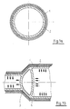
- a round hollow body is shown with an outer sleeve 1, which consists of several layers, not specified, to which an inner sleeve 2 directly abuts on the inside.
- the outer sleeve 1 which is composed of several layers, the inner sleeve 2 inserted therein and two intermediate floors 3, 4 integrally connected thereto can be seen in the area of cross-sectional jumps.
- the intermediate floors 3, 4 are arched in such a way that they are flattened under plastic deformation during the internal pressurization of the inner sleeve 2 indicated by arrows in order to achieve an increased prestress in the outer sleeve 1.
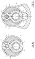
- FIGS. 2a and 2c A round hollow body is shown in FIGS. 2a and 2c, which shows the outer layer 11 consisting of several individual layers, the individual layers not being identified in any more detail.
- An inner sleeve 12 is shown at a distance from this, with support bodies 13, 14 being arranged between the two layers with wedge-shaped surfaces in the radial direction. These can move against each other during the plastic or thermal shaping of the sleeve 12, while they wedge against each other when the purely elastically widened sleeve body 11 springs back and thus participate in the compressive prestress.
- FIG. 2a shows the situation before the inner sleeve 12 is formed, the support bodies 13, 14 being offset against one another at the contact surfaces.
- FIG. 2c shows the situation after the reshaping of the inner sleeve 12 and a radial displacement of the inner support body 13 between the outer support body 14, which hold the elastically prestressed outer layer 14 in this position on an enlarged support circumference in a mutually distributed position.
- the inner sleeve 12 can be used thermally undercooled or plastically expanded after stress-free insertion.
- FIGS. 2b and 2d show a hollow body with an outer layer 21 consisting of two circular arcs and two tangential connections and a plurality of round or oval sleeves 22, 23, 24 inserted therein, which are used to generate an elastic compressive prestress in the outer layer 21 internal expansion and plastic deformation have been subjected.
- Support bodies 25, 26, 27 are located between two of the sleeves; 28, 29, 30 high pressure rigidity (ceramic) are used, which serve to transmit pressure from the areas of the sleeve body not directly adjacent to the outer layer 21 and which shift during the plastic or thermal shaping of the sleeves 22, 23, 24 against each other while they are moving wedge against each other when the purely elastically widened outer layer 21 springs back and thus participate in the compressive prestress.
- FIG. 1 shows a hollow body with an outer layer 21 consisting of two circular arcs and two tangential connections and a plurality of round or oval sleeves 22, 23, 24 inserted therein, which are used to generate an elastic compressive prestress in the outer layer 21 internal expansion and plastic deformation have been
- FIG. 2b shows the situation before the shaping of the inner sleeves 22, 23, 24, the support bodies being alternately offset inwards and outwards on their contact surfaces.
- FIG. 2d shows the situation after the reshaping of the inner sleeves 22, 23, 24, the support bodies 26, 29, which are initially displaced inwards, being displaced radially outwards between the other support bodies 25, 27, 28, 30, and the support bodies as a whole hold the elastically prestressed outer layer 21 on an enlarged outer circumference in a mutually distributed position.
- the inner sleeves can be used undercooled or expanded mechanically or hydraulically to plastic deformation after stress-free insertion.
- FIG. 3a shows a section of a crankshaft that has two base pins 31, 32 and one crank pin 33.
- a counterweight 34 is arranged on a crank arm.
- the crankshaft consists of an outer sleeve 35 and inner plastically formed sleeves 36, 37, 38 inserted therein in the region of the pins and 39, 40, 41, 42 in the region of the crank arms.
- the outer sleeve 35 is each made of nested pin parts 43, 44; 45, 46; 47, 48 assembled, which alternately attach to the crank arms 49, 50.
- FIG. 3b shows the crank arm 49 in a schematic cross section, the outer body 35, which is approximately 8-shaped in the region of the cheek, and which is supplemented to form an annular shape via webs 51, 52.
- the plastically widened sleeves 39 and 41 are used to generate the tensile pretension in the 8-shaped outer body 35, and to produce and hold the pretension in the webs 51, 52, approximately crescent-shaped shaped bodies 53, 54.
- crank web 50 can be seen in cross section, in which the counterweight 34 is attached to the approximately 8-shaped outer layer 35 and which is partially supplemented by webs 55, 56 to form a ring.
- the plastically widened sleeves 40 and 42 are shown in section, as well as crescent-shaped shaped bodies 57, 58 for generating a uniform prestress in the webs 55, 56.
- the shaped bodies are inserted by axially pressing in with a conical shape and with a self-locking angle of the conical surfaces to generate the prestress in the webs 51, 52, 55, 56.
- crank arm 49 is shown in a similar representation as in Figure 3b.
- multi-part clamping bodies 59, 60, 61; 62, 63, 64 are shown, which have a wedge-shaped cross-section and lead to a pretension in the webs 53, 54 when inserted.
- crank arm 50 is shown in a similar representation as in Fig. 3c.
- multi-part clamping bodies 65, 66, 67; 68, 69, 70 are provided which have mutually displacing wedge surfaces which have angles in the area of self-locking.
- the clamping bodies are conical or wedge-shaped in the axial direction and also have a wedge shape in cross section, the angles in each case being in the region of the self-locking.
Landscapes
- Engineering & Computer Science (AREA)
- General Engineering & Computer Science (AREA)
- Mechanical Engineering (AREA)
- Ocean & Marine Engineering (AREA)
- Shafts, Cranks, Connecting Bars, And Related Bearings (AREA)
- Laminated Bodies (AREA)
- Separation Using Semi-Permeable Membranes (AREA)
- Rigid Pipes And Flexible Pipes (AREA)
- Moulding By Coating Moulds (AREA)
- Prostheses (AREA)
Abstract
Description
Die Erfindung betrifft einen Verbundhohlkörper zur Aufnahme von Drehmomenten und/oder Zug-, Druck- oder Biegekräften, wobei in einer äußeren Materialschicht durch in senkrechter Richtung zur Längsachse druckaufnehmende innere Stützmittel im wesentlichen über die gesamte axiale Länge eine jeweils über dem Umfang gleichmäßige Zugvorspannung in Umfangsrichtung herrscht.The invention relates to a composite hollow body for absorbing torques and / or tensile, compressive or bending forces, wherein in an outer material layer by pressure-absorbing inner support means in the direction perpendicular to the longitudinal axis, a tensile prestress which is uniform over the circumference in each case essentially over the entire axial length prevails.
Verbundhohlkörper sind beispielsweise aus der EP-A- 0 212 130 bekannt, bei der ein Armierungszylinder auf ein Rohrstück so aufgebracht wird, daß im Rohrstück eine Druckvorrichtung und im Armierungszylinder eine Zugvorspannung bestehen bleibt. Der Armierungszylinder besteht hierbei vorzugsweise aus einem Faserverbundwerkstoff und das Ineinanderschieben der beiden Teile wird durch elastische Verformung im Sinne eines Aufweitens des Armierungskörpers und eines radialen Zusammendrückens des Rohrkörpers ermöglicht, wobei beim Ausgleich die
Der vorliegenden Erfindung liegt die Aufgabe zugrunde, verschiedene Elemente in Form von Verbundhohlkörpern bereitzustellen, die sich bei leichter Bauweise durch hohe Festigkeit auszeichnen und dabei leicht herstellbar sind.Composite hollow bodies are known, for example, from EP-A-0 212 130, in which a reinforcement cylinder is applied to a pipe section in such a way that a pressure device remains in the pipe section and a tensile prestress remains in the reinforcement cylinder. The reinforcement cylinder here preferably consists of a fiber composite material and the pushing together of the two parts is made possible by elastic deformation in the sense of widening of the reinforcement body and a radial compression of the tubular body, the compensation being the
The present invention has for its object to provide various elements in the form of composite hollow bodies, which are characterized by high strength with a lightweight construction and are easy to manufacture.
Diese Aufgabe wird bei einem gattungsgemäßen Verbundhohlkörper dadurch gelöst, daß an der äußeren Schicht mehrere über Teilumfänge anliegende Ring- oder Hülsenkörper insbesondere in Verbindung mit dazwischenliegenden Formkörpern, die Stützmittel bilden. Die hiermit zu erzeugenden Körper sind für Anwendungsfälle geeignet, bei denen der Querschnitt des Hohlkörpers nicht rund ist, wobei ein bevorzugtes Beispiel in Pleuelstangen zu sehen ist. Es werden hierbei mehrere runde Hülsen in einen die äußere Kontur vorgebenden Körper eingesetzt, die dann mit an sich bekannten Mitteln plastisch aufgeweitet werden. Die zwischen der äußeren Schicht und den inneren Hülsen liegenden Zwischenräume sind durch mehrere Formkörper, welche Gleitfugen untereinander mit einem Winkel zur Richtung der Rückfederungskraft, der eine Selbsthemmung bewirkt, aufweisen, zu ergänzen, die jeweils äußersten entgegengesetzten Hülsen können unmittelbar als Pleuelaugen Verwendung finden.This object is achieved in the case of a composite hollow body of the generic type in that a plurality of ring or sleeve bodies lying over partial circumferences, in particular in connection with intermediate shaped bodies, which form support means, on the outer layer. The bodies to be produced with this are suitable for applications in which the cross section of the hollow body is not round, a preferred example being shown in connecting rods. In this case, several round sleeves are inserted into a body which defines the outer contour, which are then plastically expanded using means known per se. The intermediate spaces between the outer layer and the inner sleeves are to be supplemented by a plurality of shaped bodies which have sliding joints with one another at an angle to the direction of the resilience, which causes self-locking, the outermost opposite sleeves can be used directly as connecting rod eyes.
Damit ergibt sich beim Aufweiten eine relativ geringe Kraft zur Verformung der Stützmittel und nach dem Aufweiten eine sehr große Stützwirkung. Auch hier entsteht in der die äußere Kontur vorgebenden Schicht eine gleichmäßige Zugvorspannung, während die inneren Hülsen unter Druckvorspannung stehen. Das vorgespannte Material des Hohlkörpers ergibt bei leichter Bauweise hohe Formstabilität.This results in a relatively small force for deformation of the support means during expansion and a very large support effect after expansion. Here, too, a uniform tensile pre-tension is created in the layer that defines the outer contour, while the inner sleeves are under pre-tension. The pre-stressed material of the hollow body results in high dimensional stability with a light construction.
Nach einer weiteren bevorzugten Ausführung, die sowohl Verbundhohlkörper mit rundem Querschnitt als auch solche mit unrundem Querschnitt betreffen kann, sind zwischen der äußeren Schicht und einer oder mehreren innenliegenden Hülsen sich gegeneinander durch Selbsthemmung abstützende Klemmkörper vorgesehen, wobei das plastisch umgeformte Material der innenliegenden Schicht oder der Hülsen wiederum eine geringere Streckgrenze aufweist, als das der äußeren Schicht. Durch plastisches Aufweiten werden hierbei die nach außen gegeneinander gleitend verschiebbaren, sich nach innen durch Selbsthemmung und damit Verhinderung des Rückgleitens abstützenden Klemmkörper in ihrer Lage so verändert, daß sie an der Aufrechterhaltung der Vorspannung in der äußeren Schicht durch ihre große Druckfestigkeit entscheidend teilhaben. Die inneren plastisch verformte Materialschicht fixiert die Klemmkörper sicher in der aufgeweiteten Position.According to a further preferred embodiment, which can relate to both composite hollow bodies with a round cross section and those with a non-round cross section, self-locking clamping bodies are provided between the outer layer and one or more inner sleeves, the plastically deformed material of the inner layer or the Sleeves in turn has a lower yield strength than that of the outer layer. By plastic widening, the position of the clamping body, which can be slid outwards against one another and is supported inward by self-locking and thus preventing sliding back, is changed in such a way that they play a decisive role in maintaining the pretension in the outer layer due to their high compressive strength. The inner plastically deformed material layer securely fixes the sprags in the expanded position.
Als bevorzugte Werkstoffe für die äußere Schicht kommen Materialien mit hoher Zugfestigkeit und hoher Streckgrenze infrage, beispielsweise Vergütungsstähle, Federstähle, Titan oder Faserverbundwerkstoffe. Als Werkstoffe für die Hülsen, die plastisch verformbar sein müssen, sind entsprechend ausgewählte Baustähle, Kohlenstoffstähle oder Nichteisenmetalle vorzuschlagen. Die äußere Schicht und die innere Schicht beziehungsweise die inneren Hülsen können jeweils ihrerseits aus mehreren Lagen mit nach außen zunehmender Festigkeit bestehen. Die Klemmkörper der Zwischenschicht sind vorzugsweise aus Keramik oder einem drucksteifen hartem Werkstoff vorzusehen, wobei auch spröde Werkstoffe möglich sind. Durch die bleibende Vorspannung zwischen äußerer und innerer Schicht wird ein Haftschluß auch zwischen den einzelnen Lagen erzeugt. Durch den Haftschluß ist es möglich, die äußere Schicht und/oder die innere Schicht, beziehungsweise die inneren Hülsen aus mehreren axialen Einzelabschnitten aufzubauen, wobei bei einem Vorliegen von Trennfugen in der inneren und äußeren Schicht diese axial weit genug voneinander versetzt sein sollen. Der Verbundhohlkörper ist hierdurch aus kürzeren Hülsenstücken aufzubauen. Die Wandstärken der Verbundschichten bzw. die Festigkeitskennwerte bei aus Einzelabschniten axial zusammengesetzten Hohlkörpern können in Längsrichtung abgestuft werden, so daß sich mit unterschiedlichem Aufweitdrücken nacheinander wirkend oder mit gleichem Aufweitdruck gleichzeitig wirkend eine unterschiedliche axiale und radiale Vorspannung ergibt, wobei letztere in einzelnen Querschnitten jeweils etwa gleichmäßig ist.Materials with high tensile strength and high yield strength, such as quenched and tempered steels, spring steels, titanium or fiber composite materials, are considered as preferred materials for the outer layer. Appropriate selected structural steels, carbon steels or non-ferrous metals are to be proposed as materials for the sleeves, which must be plastically deformable. The outer layer and the inner layer or the inner sleeves can each consist of several layers with increasing strength. The clamping bodies of the intermediate layer should preferably be made of ceramic or a rigid material that is resistant to pressure, and brittle materials are also possible. Due to the permanent prestress between the outer and inner layers, an adhesive closure is also created between the individual layers. By means of the adhesive closure, it is possible to construct the outer layer and / or the inner layer or the inner sleeves from a plurality of axial individual sections, with the presence of Partition joints in the inner and outer layer should be offset axially far enough from each other. The composite hollow body is hereby constructed from shorter sleeve pieces. The wall thicknesses of the composite layers or the strength values in the case of hollow bodies composed of individual sections axially can be graduated in the longitudinal direction, so that with different expansion pressures acting in succession or simultaneously with the same expansion pressure, there is a different axial and radial prestress, the latter being approximately uniform in each case in individual cross sections is.
Das plastische Aufweiten der jeweils inneren Schicht oder der jeweils inneren Hülsen ist durch innere Druckaufgabe, die quasistatisch oder pulsierend oder in explosionsartiger Entfaltung erfolgen kann, bevorzugt gegen die Abstützung einer äußeren Form, das heißt eines Gesenkes vorzunehmen. In dieser Form ist dabei ein Aufweitspiel vorzusehen, wobei vor Erreichen der Elastizitätsgrenze die Außenschicht sich an der sehr stabilen Wandung anlegen soll, so daß der Aufweitdruck nicht eng begrenzt werden muß.The plastic expansion of the respective inner layer or the respective inner sleeves is preferably carried out by means of an internal pressure application, which can be quasi-static or pulsating or in an explosion-like manner, against the support of an outer shape, that is to say a die. An expansion play is to be provided in this form, the outer layer being intended to lie against the very stable wall before the elastic limit is reached, so that the expansion pressure does not have to be narrowly limited.
In die jeweils innere Schicht oder die inneren Hülsen können zusätzliche Stützmittel in Form von Querböden oder dergleichen eingepreßt oder eingeformt sein, die beispielsweise im Bereich von Querschnittssprüngen für eine erhöhte radiale Steifigkeit sorgen.Additional support means in the form of transverse bottoms or the like can be pressed or molded into the respective inner layer or inner sleeves, which provide increased radial rigidity, for example in the area of cross-sectional jumps.
Die jeweils in der inneren und äußeren Schicht aufrechterhaltene Vorspannung kann auch durch andere Fügeverfahren, insbesondere thermisches Fügen (Schrumpfen, Wachsen) oder durch reine axiale Preßverbindung erzeugt werden, wobei das Verhältnis der Streckgrenzen der Materialien von innerer und äußerer Schicht in der Bedeutung zurücktritt.The prestressing maintained in the inner and outer layer can also be generated by other joining methods, in particular thermal joining (shrinking, waxing) or by pure axial press connection, the importance of the ratio of the yield strengths of the materials of the inner and outer layer decreasing.
Bevorzugte Ausführungsbeispiele und das Umfeld der Erfindung sind in den Zeichnungen beschrieben:
- Fig. 1a
- zeigt einen Verbundhohlkörper im Querschnitt,
- Fig. 1b
- zeigt einen Hohlkörper nach Fig. 1a im Längsschnitt
- Fig. 2a
- zeigt einen erfindungsgemäßen Verbundhohlkörper vor dem Aufweiten im Querschnitt,
- Fig. 2b
- zeigt einen erfindungsgemäßen Verbundhohlkörper nach einer weiteren Lösung vor dem Aufweiten im Querschnitt,
- Fig. 2c
- zeigt einen Hohlkörper nach Fig. 2a nach dem Aufweiten im Querschnitt,
- Fig. 2d
- zeigt einen Hohlkörper nach Fig. 2b nach dem Aufweiten im Querschnitt,
- Fig. 3a
- zeigt einen erfindungsgemäßen Verbundhohlkörper als Kurbelwelle im Längsschnitt,
- Fig. 3b
- zeigt einen Hohlkörper nach Fig. 3a in einem ersten Querschnitt in einer ersten Aufsführung,
- Fig. 3c
- zeigt einen Hohlkörper nach Fig. 3a in einem zweiten Querschnitt in einer ersten Ausführung,
- Fig. 3d
- zeigt einen Hohlkörper nach Fig. 3a in einem ersten Querschnitt in einer zweiten Aufsführung,
- Fig. 3e
- zeigt einen Hohlkörper nach Fig. 3a in einem zweiten Querschnitt in einer zweiten Ausführung.
- Fig. 1a
- shows a composite hollow body in cross section,
- Fig. 1b
- shows a hollow body according to Fig. 1a in longitudinal section
- Fig. 2a
- shows a composite hollow body according to the invention before expansion in cross section,
- Fig. 2b
- shows a composite hollow body according to the invention after a further solution before expansion in cross section,
- Fig. 2c
- shows a hollow body according to FIG. 2a after expansion in cross section,
- Fig. 2d
- 2b shows a hollow body according to FIG. 2b after expansion in cross section,
- Fig. 3a
- shows a composite hollow body according to the invention as a crankshaft in longitudinal section,
- Fig. 3b
- 3a shows a hollow body according to FIG. 3a in a first cross section in a first performance,
- Fig. 3c
- shows a hollow body according to Fig. 3a in a second cross section in a first embodiment,
- Fig. 3d
- 3a shows a hollow body according to FIG. 3a in a first cross section in a second performance,
- Fig. 3e
- shows a hollow body according to Fig. 3a in a second cross section in a second embodiment.
In Fig. 1a ist ein runder Hohlkörper mit einer äußeren Hülse 1 gezeigt, die aus mehreren nicht näher bezeichneten Lagen besteht, an die sich innen unmittelbar eine innere Hülse 2 anlegt.In Fig. 1a, a round hollow body is shown with an outer sleeve 1, which consists of several layers, not specified, to which an
In Figur 1b sind die aus mehreren Schichten aufgebaute äußere Hülse 1, die darin eingesetzte innere Hülse 2 und zwei mit dieser einstückig verbundene Zwischenböden 3, 4 im Bereich von Querschnittssprüngen erkennbar. Die Zwischenböden 3, 4 sind so gewölbt, daß sie bei der durch Pfeile angedeuteten inneren Druckbeaufschlagung der inneren Hülse 2, zur Erzielung einer erhöhten Vorspannung in der Außenhülse 1, unter plastischer Umformung flachgedrückt werden.In Figure 1b, the outer sleeve 1, which is composed of several layers, the
In den Figuren 2a und 2c ist ein runder Hohlkörper wiedergegeben, der die aus mehreren einzelnen Lagen bestehende Außenschicht 11 zeigt, wobei die einzelnen Lagen nicht näher bezeichnet sind. Mit Abstand hierzu ist eine innere Hülse 12 wiedergegeben, wobei zwischen den beiden Schichten mit in radialer Richtung keilförmigen Flächen versehene Stützkörper 13, 14 angeordnet sind. Diese können sich beim plastischen oder thermischen Umformen der Hülse 12 gegeneinander verschieben, während sie sich beim Rückfedern des rein elastisch aufgeweiteten Hülsenkörpes 11 gegeneinander verkeilen und damit an der Druckvorspannung teilhaben. In Fig. 2a ist die Situation vor dem Umformen der inneren Hülse 12 dargestellt, wobei die Stützkörper 13, 14 an den Kontaktflächen gegeneinander versetzt sind. In Fig. 2c ist die Situation nach dem Umformen der inneren Hülse 12 und einem radialen Verschieben der inneren Stützkörper 13 zwischen die äußeren Stützkörper 14 gezeigt, die in dieser Position die elastisch vorgespannte Außenschicht 14 auf einem vergrößerten Stützumfang in gegeneinander verteilter Stellung festhalten. Die Innenhülse 12 kann kann thermisch unterkühlt eingesetzt werden oder nach dem spannungsfreien Einsetzen plastisch aufgeweitet werden.A round hollow body is shown in FIGS. 2a and 2c, which shows the
In den Figuren 2b und 2d ist ein Hohlkörper mit einer aus zwei Kreisbögen und zwei tangentialen Verbindungen bestehenden äußeren Schicht 21 und mehreren darin eingesetzten runden, beziehungsweise ovalen Hülsen 22, 23, 24 gezeigt, die zur Erzeugung einer elastischen Druckvorspannung in der äußeren Schicht 21 einer inneren Aufweitung und plastischen Verformung unterworfen worden sind. Jeweils zwischen zwei der Hülsen sind Stützkörper 25, 26, 27; 28, 29, 30 hoher Drucksteifigkeit (Keramik) eingesetzt, die der Druckübertragung von den nicht unmittelbar anliegenden Bereichen der Hülsenkörper auf die äußere Schicht 21 dienen und die sich beim plastischen oder thermischen Umformen der Hülsen 22, 23, 24 gegeneinander verschieben, während sie sich beim Rückfedern der rein elastisch aufgeweiteten äußeren Schicht 21 gegeneinander verkeilen und damit an der Druckvorspannung teilhaben. In Figur 2b ist die Situation vor dem Umformen der inneren Hülsen 22, 23, 24 dargestellt, wobei die Stützkörper an ihren Kontaktflächen gegeneinander abwechselnd nach innen und außen versetzt sind. In Figur 2d ist die Situation nach dem Umformen der inneren Hülsen 22, 23, 24 dargestellt, wobei die zunächst nach innen versetzten Stützkörper 26, 29 radial nach außen zwischen die übrigen Stützkörper 25, 27, 28, 30 verschoben sind, und die Stützkörper insgesamt die elastisch vorgespannte Außenschicht 21 auf einem vergrößerten Außenumfang in gegeneinander verteilter Stellung festhalten. Die Innenhülsen können thermisch unterkühlt eingesetzt werden oder nach dem spannungsfreien Einsetzen mechanisch oder hydraulisch bis zur plastischen Verformung aufgeweitet werden.FIGS. 2b and 2d show a hollow body with an
Durch radiale Pfeile ist jeweils angedeutet, daß durch Gegenhalten ein Aufweiten nach Art der strichpunktierten dünnen Linie verhindert werden kann und die Außenschicht die gezeichnete Form, die sie von Beginn aufweist, auch später beibehält. In Figur 3a ist ein Abschnitt einer Kurbelwelle darge- stellt, der zwei Grundzapfen 31, 32 und einen Hubzapfen 33 aufweist. An einer Kurbelwange ist ein Gegengewicht 34 angeordnet. Die Kurbelwelle besteht aus einer äußeren Hülse 35 und darin eingesetzten inneren plastisch um- geformten Hülsen 36, 37, 38 im Bereich der Zapfen und 39, 40, 41, 42 im Bereich der Kurbelwangen. Die äußere Hülse 35 ist dabei jeweils aus ineinandergesteckten Zapfenteilen 43, 44; 45, 46; 47, 48 zusammgengesetzt, die wechselseitig an den Kurbelwangen 49, 50 ansetzen.Radial arrows indicate that counter-widening can be prevented in the manner of the dash-dotted thin line and the outer layer retains the shape it has from the beginning. FIG. 3a shows a section of a crankshaft that has two base pins 31, 32 and one crank
In Figur 3b ist die Kurbelwange 49 im schematisierten Querschnitt gezeigt, wobei der im Bereich der Wange etwa 8-förmige Außenkörper 35 erkennbar ist, der über Stege 51, 52 zu einer Ringform ergänzt ist. Zur Erzeugung der Zugvorspannung in dem 8-förmigen Außenkörper 35 sind die plastisch aufgeweiteten Hülsen 39 und 41 eingesetzt, sowie zur Erzeugung und Haltung der Vorspannung in den Stegen 51, 52 etwa mondsichelförmige Formkörper 53, 54.3b shows the
In Figur 3c ist die Kurbelwange 50 im Querschnitt erkennbar, bei der an der etwa 8-förmigen Außenschicht 35 das Gegengewicht 34 angesetzt ist und die durch Stege 55, 56 teilweise zur Ringform ergänzt ist. Auch hier sind die plastisch aufgeweiteten Hülsen 40 und 42 im Schnitt dargestellt, sowie mondsichelförmige Formkörper 57, 58 zur Erzeugung einer gleichmäßigen Vorspannung in den Stegen 55, 56.In Figure 3c, the
Die Formkörper sind in diesem Beispiel durch axiales Einpressen mit einer konischen Form und mit einem Selbsthemmung bewirkenden Winkel der konischen Flächen zur Erzeugung der Vorspannung in den Stegen 51, 52, 55, 56 eingesetzt.In this example, the shaped bodies are inserted by axially pressing in with a conical shape and with a self-locking angle of the conical surfaces to generate the prestress in the
In Figur 3d ist die Kurbelwange 49 in ähnlicher Darstellung wie in Figur 3b gezeigt. Es sind jedoch mehrteilige Klemmkörper 59, 60, 61; 62, 63, 64 gezeigt, die im Querschnitt keilförmige Form haben und zu einer Vorspannung in den Stegen 53, 54 beim Einsetzen führen.In Figure 3d, the
In Figur 3e ist die Kurbelwange 50 in ähnlicher Darstellung wie in Fig. 3c gezeigt. Auch hier sind entsprechend Figur 3d mehrteilige Klemmkörper 65, 66, 67; 68, 69, 70 vorgesehen, die sich gegeneinander verschiebende Keilflächen haben, die Winkel im Vereich der Selbsthemmung haben.In Figure 3e, the
Die Klemmkörper sind in axialer Richtung konisch bzw. keilförmig und haben auch im Querschnitt Keilform, wobei jeweils die Winkel im Bereich der Selbsthemmung liegen. Beim axialen Einpressen und ggfs. beim radialen Aufweiten der Hülsen 39, 40, 41, 42 verschieben sich die Klemmkörper gegeneinander und sind gegen ein Rückfedern durch die Selbsthemmung an ihren Gleitflächen gesichert, so daß sie eine Vorspannung in den Stegen 51, 52, 55, 56 erzeugen und aufrechterhalten.The clamping bodies are conical or wedge-shaped in the axial direction and also have a wedge shape in cross section, the angles in each case being in the region of the self-locking. When the
Claims (6)
Applications Claiming Priority (3)
| Application Number | Priority Date | Filing Date | Title |
|---|---|---|---|
| DE3837293 | 1988-11-03 | ||
| DE3837293A DE3837293A1 (en) | 1988-11-03 | 1988-11-03 | CONNECTED HOLLOW BODY |
| EP89118952A EP0366989B1 (en) | 1988-11-03 | 1989-10-12 | Hollow composite member |
Related Parent Applications (1)
| Application Number | Title | Priority Date | Filing Date |
|---|---|---|---|
| EP89118952.4 Division | 1989-10-12 |
Publications (3)
| Publication Number | Publication Date |
|---|---|
| EP0621410A2 true EP0621410A2 (en) | 1994-10-26 |
| EP0621410A3 EP0621410A3 (en) | 1995-04-26 |
| EP0621410B1 EP0621410B1 (en) | 1997-08-20 |
Family
ID=6366380
Family Applications (2)
| Application Number | Title | Priority Date | Filing Date |
|---|---|---|---|
| EP94110337A Expired - Lifetime EP0621410B1 (en) | 1988-11-03 | 1989-10-12 | Hollow composite member |
| EP89118952A Expired - Lifetime EP0366989B1 (en) | 1988-11-03 | 1989-10-12 | Hollow composite member |
Family Applications After (1)
| Application Number | Title | Priority Date | Filing Date |
|---|---|---|---|
| EP89118952A Expired - Lifetime EP0366989B1 (en) | 1988-11-03 | 1989-10-12 | Hollow composite member |
Country Status (11)
| Country | Link |
|---|---|
| US (1) | US5064726A (en) |
| EP (2) | EP0621410B1 (en) |
| JP (1) | JPH0622954B2 (en) |
| KR (1) | KR930010006B1 (en) |
| CN (1) | CN1015733B (en) |
| BR (1) | BR8905609A (en) |
| CA (1) | CA2002194C (en) |
| DE (3) | DE3837293A1 (en) |
| ES (2) | ES2105431T3 (en) |
| MX (1) | MX171809B (en) |
| RU (2) | RU2013669C1 (en) |
Cited By (3)
| Publication number | Priority date | Publication date | Assignee | Title |
|---|---|---|---|---|
| FR2851804A1 (en) * | 2003-02-27 | 2004-09-03 | Hutchinson | ANTI-VIBRATORY CONNECTING ROD AND MANUFACTURING METHOD THEREOF |
| US7246965B2 (en) | 2003-03-14 | 2007-07-24 | Hutchinson | Method of assembling a link to a support, and a vibration-damping device manufactured by said method |
| DE102015118890B4 (en) | 2015-11-04 | 2022-12-22 | Volkswagen Aktiengesellschaft | Connecting rod, internal combustion engine and method for manufacturing a connecting rod |
Families Citing this family (8)
| Publication number | Priority date | Publication date | Assignee | Title |
|---|---|---|---|---|
| DE19617219C2 (en) * | 1996-04-30 | 1998-04-30 | Daimler Benz Ag | Method of making a hollow shaft |
| DE19738612A1 (en) * | 1997-09-04 | 1999-03-11 | Volkswagen Ag | Camshaft for internal-combustion engine |
| DE10140332C1 (en) * | 2001-08-16 | 2003-04-24 | Daimler Chrysler Ag | lightweight crankshaft |
| ITNA20120074A1 (en) * | 2012-12-13 | 2014-06-14 | Tepco Tecnologie Dei Polimeri E Dei Compositi | INNOVATIVE SHAFT IN COMPOSITE MATERIAL |
| JP6318733B2 (en) * | 2014-03-14 | 2018-05-09 | オムロン株式会社 | Caulking structure and caulking method, and electronic device |
| KR101664682B1 (en) * | 2015-04-14 | 2016-10-10 | 현대자동차주식회사 | Hollow drive shaft for vehicle and manufacturing meathod of the same |
| CN105042025A (en) * | 2015-05-09 | 2015-11-11 | 陈学福 | Friction type automobile differential mechanism |
| CN107795149A (en) * | 2017-11-06 | 2018-03-13 | 中国人民解放军陆军工程大学 | Lattice-reinforced composite material foam sandwich supporting column and preparation method thereof |
Citations (7)
| Publication number | Priority date | Publication date | Assignee | Title |
|---|---|---|---|---|
| US2306960A (en) * | 1940-04-11 | 1942-12-29 | Continental Aviat & Eng Corp | Shafting |
| GB1162022A (en) * | 1965-10-21 | 1969-08-20 | Bendix Corp | Improvements in or relating to Force Transmitting Members |
| US3844730A (en) * | 1968-05-10 | 1974-10-29 | Maschf Augsburg Nuernberg Ag | Process for the manufacture of a rotor or shaft of low deformability |
| DE3128744A1 (en) * | 1981-07-21 | 1983-02-10 | Deutsche Forschungs- und Versuchsanstalt für Luft- und Raumfahrt e.V., 5300 Bonn | Crankshaft |
| FR2536131A1 (en) * | 1982-11-16 | 1984-05-18 | Honda Motor Co Ltd | DRIVE SHAFT OR TRANSMISSION IN FIBER REINFORCED PLASTIC MATERIAL, AND METHOD FOR THE PRODUCTION THEREOF |
| EP0068424B1 (en) * | 1981-06-26 | 1986-04-09 | Georg Fischer Aktiengesellschaft | Composite connecting member, particularly a connecting rod or link, and method of making the same |
| EP0212130A2 (en) * | 1985-08-06 | 1987-03-04 | UNIMA Maschinenbau GmbH | Method and apparatus for sheathing tubular parts of an object, especially of a tube |
Family Cites Families (26)
| Publication number | Priority date | Publication date | Assignee | Title |
|---|---|---|---|---|
| US1441459A (en) * | 1921-02-04 | 1923-01-09 | Philadelphia Bronze Bearing & | Composite tube and method of making the same |
| US1587025A (en) * | 1924-01-25 | 1926-06-01 | Thomas E Murray | Crank shaft and method of manufacture |
| US2063325A (en) * | 1932-05-10 | 1936-12-08 | Neil R Mcleod | Process for minimizing temperature stresses in metallic structures and product thereof |
| US3466895A (en) * | 1968-03-04 | 1969-09-16 | Gen Motors Corp | Prestressed shaft |
| US3762032A (en) * | 1971-08-19 | 1973-10-02 | Gen Motors Corp | Bonding |
| SU625817A1 (en) * | 1972-06-07 | 1978-09-30 | Timoshenko Nikolaj D | Method of connecting tubes to tube walls of heat-exchangers |
| CA1139923A (en) * | 1979-02-28 | 1983-01-25 | Toshio Yoshida | Method of producing multiple-wall composite pipes |
| DE2922509A1 (en) * | 1979-05-31 | 1980-12-04 | Mannesmann Ag | METHOD AND DEVICE FOR PRODUCING CAMSHAFT |
| US4377894A (en) * | 1980-03-21 | 1983-03-29 | Kawasaki Jukogyo Kabushiki Kaisha | Method of lining inner wall surfaces of hollow articles |
| US4359811A (en) * | 1980-08-20 | 1982-11-23 | The Halcon Sd Group, Inc. | Method of coating or lining metals |
| JPS5790415A (en) * | 1980-11-26 | 1982-06-05 | Komatsu Ltd | Stepped hollow shaft manufacturing method |
| DE3124854C2 (en) * | 1981-06-24 | 1985-03-14 | Reinhard 8057 Eching Mühlbauer | High pressure injection system with ultrasonic atomization |
| DE3133209C2 (en) * | 1981-08-21 | 1985-04-25 | MTU Motoren- und Turbinen-Union München GmbH, 8000 München | Hollow composite body, in particular body of revolution and method for its production |
| JPS5865524A (en) * | 1981-10-16 | 1983-04-19 | Kawasaki Heavy Ind Ltd | Manufacture of double pipe |
| JPS58132325A (en) * | 1982-02-01 | 1983-08-06 | Mazda Motor Corp | Manufacture of hollow cam shaft |
| JPS5927354A (en) * | 1982-08-03 | 1984-02-13 | Nec Corp | Double byte error correcting circuit |
| DE3243838C2 (en) * | 1982-11-26 | 1984-11-08 | Mtu Motoren- Und Turbinen-Union Muenchen Gmbh, 8000 Muenchen | Connecting rod with a bandage made of fiber-reinforced composite material |
| JPS6167525A (en) * | 1984-09-11 | 1986-04-07 | Nippon Piston Ring Co Ltd | Cam shaft |
| JPS6188930A (en) * | 1984-10-05 | 1986-05-07 | Toyo Kohan Co Ltd | Deep-drawing method of metallic foil |
| JPH0724897B2 (en) * | 1984-10-08 | 1995-03-22 | 正信 中村 | Hollow shaft manufacturing method |
| JPS6188932A (en) * | 1984-10-08 | 1986-05-07 | Takeuchi Press Kogyo Kk | Manufacture of deformed can |
| US4658319A (en) * | 1984-10-18 | 1987-04-14 | Odetics, Inc. | Time lapse video recorder with auto monitoring function |
| DE3542071A1 (en) * | 1984-12-08 | 1986-06-12 | Volkswagen AG, 3180 Wolfsburg | Connecting rod |
| DE3610134A1 (en) * | 1986-03-26 | 1987-10-01 | Bayerische Motoren Werke Ag | Connecting rod |
| DE3800914A1 (en) * | 1988-01-14 | 1989-08-03 | Emitec Emissionstechnologie | COMPOSED SHAFT WITH INTEGRATED DRIVE ELEMENTS |
| DE3800912A1 (en) * | 1988-01-14 | 1989-07-27 | Emitec Emissionstechnologie | METHOD FOR FASTENING DRIVE ELEMENTS ON A HOLLOW SHAFT WITH THE SUPPORT RINGS |
-
1988
- 1988-11-03 DE DE3837293A patent/DE3837293A1/en not_active Ceased
-
1989
- 1989-10-12 EP EP94110337A patent/EP0621410B1/en not_active Expired - Lifetime
- 1989-10-12 DE DE58909815T patent/DE58909815D1/en not_active Expired - Fee Related
- 1989-10-12 EP EP89118952A patent/EP0366989B1/en not_active Expired - Lifetime
- 1989-10-12 ES ES94110337T patent/ES2105431T3/en not_active Expired - Lifetime
- 1989-10-12 ES ES89118952T patent/ES2070157T3/en not_active Expired - Lifetime
- 1989-10-12 DE DE58908997T patent/DE58908997D1/en not_active Expired - Fee Related
- 1989-10-19 RU SU894742357A patent/RU2013669C1/en active
- 1989-10-31 MX MX018171A patent/MX171809B/en unknown
- 1989-11-01 BR BR898905609A patent/BR8905609A/en not_active IP Right Cessation
- 1989-11-01 CN CN89108355A patent/CN1015733B/en not_active Expired
- 1989-11-02 KR KR1019890015886A patent/KR930010006B1/en not_active IP Right Cessation
- 1989-11-02 JP JP1285109A patent/JPH0622954B2/en not_active Expired - Lifetime
- 1989-11-03 US US07/431,645 patent/US5064726A/en not_active Expired - Fee Related
- 1989-11-03 CA CA002002194A patent/CA2002194C/en not_active Expired - Fee Related
-
1991
- 1991-10-19 RU SU914894697A patent/RU2053419C1/en active
Patent Citations (7)
| Publication number | Priority date | Publication date | Assignee | Title |
|---|---|---|---|---|
| US2306960A (en) * | 1940-04-11 | 1942-12-29 | Continental Aviat & Eng Corp | Shafting |
| GB1162022A (en) * | 1965-10-21 | 1969-08-20 | Bendix Corp | Improvements in or relating to Force Transmitting Members |
| US3844730A (en) * | 1968-05-10 | 1974-10-29 | Maschf Augsburg Nuernberg Ag | Process for the manufacture of a rotor or shaft of low deformability |
| EP0068424B1 (en) * | 1981-06-26 | 1986-04-09 | Georg Fischer Aktiengesellschaft | Composite connecting member, particularly a connecting rod or link, and method of making the same |
| DE3128744A1 (en) * | 1981-07-21 | 1983-02-10 | Deutsche Forschungs- und Versuchsanstalt für Luft- und Raumfahrt e.V., 5300 Bonn | Crankshaft |
| FR2536131A1 (en) * | 1982-11-16 | 1984-05-18 | Honda Motor Co Ltd | DRIVE SHAFT OR TRANSMISSION IN FIBER REINFORCED PLASTIC MATERIAL, AND METHOD FOR THE PRODUCTION THEREOF |
| EP0212130A2 (en) * | 1985-08-06 | 1987-03-04 | UNIMA Maschinenbau GmbH | Method and apparatus for sheathing tubular parts of an object, especially of a tube |
Cited By (4)
| Publication number | Priority date | Publication date | Assignee | Title |
|---|---|---|---|---|
| FR2851804A1 (en) * | 2003-02-27 | 2004-09-03 | Hutchinson | ANTI-VIBRATORY CONNECTING ROD AND MANUFACTURING METHOD THEREOF |
| EP1452750A3 (en) * | 2003-02-27 | 2006-09-20 | Hutchinson | Antivibration connecting rod and method for manufacturing the same |
| US7246965B2 (en) | 2003-03-14 | 2007-07-24 | Hutchinson | Method of assembling a link to a support, and a vibration-damping device manufactured by said method |
| DE102015118890B4 (en) | 2015-11-04 | 2022-12-22 | Volkswagen Aktiengesellschaft | Connecting rod, internal combustion engine and method for manufacturing a connecting rod |
Also Published As
| Publication number | Publication date |
|---|---|
| BR8905609A (en) | 1990-05-29 |
| ES2070157T3 (en) | 1995-06-01 |
| MX171809B (en) | 1993-11-16 |
| RU2053419C1 (en) | 1996-01-27 |
| CN1042400A (en) | 1990-05-23 |
| CA2002194C (en) | 1994-12-13 |
| CN1015733B (en) | 1992-03-04 |
| DE58909815D1 (en) | 1997-09-25 |
| EP0621410A3 (en) | 1995-04-26 |
| ES2105431T3 (en) | 1997-10-16 |
| EP0366989A2 (en) | 1990-05-09 |
| EP0366989B1 (en) | 1995-02-15 |
| RU2013669C1 (en) | 1994-05-30 |
| US5064726A (en) | 1991-11-12 |
| JPH0622954B2 (en) | 1994-03-30 |
| JPH02187328A (en) | 1990-07-23 |
| DE58908997D1 (en) | 1995-03-23 |
| DE3837293A1 (en) | 1990-05-17 |
| KR930010006B1 (en) | 1993-10-14 |
| KR900008192A (en) | 1990-06-02 |
| CA2002194A1 (en) | 1990-05-03 |
| EP0621410B1 (en) | 1997-08-20 |
| EP0366989A3 (en) | 1990-12-27 |
Similar Documents
| Publication | Publication Date | Title |
|---|---|---|
| EP0328009B1 (en) | Assembled shaft, especially a camshaft, crankshaft or gear box shaft | |
| EP0265663B2 (en) | Method of producing a camshaft, as well as a camshaft made from a tube, and elements placed thereon | |
| DE19606732C2 (en) | Joined multilayer waves | |
| EP0324498B1 (en) | Drive shaft composed of several layers | |
| DE3323640A1 (en) | CONNECTING DEVICE BETWEEN A TUBULAR BODY AND A RING-SHAPED PART AND METHOD FOR PRODUCING THIS CONNECTION | |
| DE19615505C2 (en) | Double plate body | |
| EP0621410B1 (en) | Hollow composite member | |
| EP0328007B1 (en) | Assembled gear axle | |
| WO2007014537A1 (en) | Transmission, in particular for a motor vehicle, and shaft or shafts for said transmission, and method for producing shafts of said type | |
| EP3953602A1 (en) | Flexible spring element made of a fibre-plastic composite material | |
| EP0324500B1 (en) | Composite shaft with integrated drive elements | |
| DE3204093C2 (en) | Connecting rod for an internal combustion piston engine | |
| DE10260115B4 (en) | Camshaft made of carbon fiber composite material (CFRP) | |
| EP0366912B1 (en) | Crankshaft with hollow cranks | |
| DE69700495T2 (en) | METHOD AND MATRICE FOR THE PRODUCTION OF COMPONENTS WITH TORSION TUBES HAVING SPIRAL-SHAPED GROOVES | |
| DE3309002A1 (en) | VIBRATIONS INSULATING BEARING | |
| DE102007033913A1 (en) | Vibration-reduced, torque transmission device for e.g. steering column of motor vehicle, has vibration-reduced damping device provided between two identical transmission parts including axial projecting catch formations | |
| DE102010030484A1 (en) | Strut element e.g. hinged support, for coupling end pieces for receiving e.g. elastomeric joint, in automotive industry, has end part comprising conical cross-section extending beyond outer contour in connecting region | |
| DE102020212623A1 (en) | Multipoint link for a chassis of a vehicle | |
| AT5130U1 (en) | PUSH ROD, IN PARTICULAR FOR A VALVE ACTUATING DEVICE OF AN INTERNAL COMBUSTION ENGINE | |
| DE3844747C2 (en) | Force take-up composite hollow body | |
| DE3844746A1 (en) | Connecting rod | |
| DE60217575T2 (en) | Method of making a metal matrix composite tube-plate assembly | |
| WO2003069179A1 (en) | Brake disc comprising a connection between the hub well and friction ring, produced by internal hydroforming | |
| DE102017208309A1 (en) | Method for producing an endless fiber-reinforced chassis component |
Legal Events
| Date | Code | Title | Description |
|---|---|---|---|
| PUAI | Public reference made under article 153(3) epc to a published international application that has entered the european phase |
Free format text: ORIGINAL CODE: 0009012 |
|
| AC | Divisional application: reference to earlier application |
Ref document number: 366989 Country of ref document: EP |
|
| AK | Designated contracting states |
Kind code of ref document: A2 Designated state(s): DE ES FR GB IT SE |
|
| PUAL | Search report despatched |
Free format text: ORIGINAL CODE: 0009013 |
|
| RHK1 | Main classification (correction) |
Ipc: F16C 3/02 |
|
| AK | Designated contracting states |
Kind code of ref document: A3 Designated state(s): DE ES FR GB IT SE |
|
| 17P | Request for examination filed |
Effective date: 19950518 |
|
| 17Q | First examination report despatched |
Effective date: 19960326 |
|
| GRAG | Despatch of communication of intention to grant |
Free format text: ORIGINAL CODE: EPIDOS AGRA |
|
| GRAH | Despatch of communication of intention to grant a patent |
Free format text: ORIGINAL CODE: EPIDOS IGRA |
|
| GRAH | Despatch of communication of intention to grant a patent |
Free format text: ORIGINAL CODE: EPIDOS IGRA |
|
| GRAA | (expected) grant |
Free format text: ORIGINAL CODE: 0009210 |
|
| AC | Divisional application: reference to earlier application |
Ref document number: 366989 Country of ref document: EP |
|
| AK | Designated contracting states |
Kind code of ref document: B1 Designated state(s): DE ES FR GB IT SE |
|
| REF | Corresponds to: |
Ref document number: 58909815 Country of ref document: DE Date of ref document: 19970925 |
|
| ET | Fr: translation filed | ||
| REG | Reference to a national code |
Ref country code: ES Ref legal event code: FG2A Ref document number: 2105431 Country of ref document: ES Kind code of ref document: T3 |
|
| GBT | Gb: translation of ep patent filed (gb section 77(6)(a)/1977) |
Effective date: 19970925 |
|
| PLBE | No opposition filed within time limit |
Free format text: ORIGINAL CODE: 0009261 |
|
| STAA | Information on the status of an ep patent application or granted ep patent |
Free format text: STATUS: NO OPPOSITION FILED WITHIN TIME LIMIT |
|
| 26N | No opposition filed | ||
| PGFP | Annual fee paid to national office [announced via postgrant information from national office to epo] |
Ref country code: GB Payment date: 20011012 Year of fee payment: 13 Ref country code: FR Payment date: 20011012 Year of fee payment: 13 Ref country code: DE Payment date: 20011012 Year of fee payment: 13 |
|
| PGFP | Annual fee paid to national office [announced via postgrant information from national office to epo] |
Ref country code: SE Payment date: 20011015 Year of fee payment: 13 |
|
| PGFP | Annual fee paid to national office [announced via postgrant information from national office to epo] |
Ref country code: ES Payment date: 20011031 Year of fee payment: 13 |
|
| REG | Reference to a national code |
Ref country code: GB Ref legal event code: IF02 |
|
| PG25 | Lapsed in a contracting state [announced via postgrant information from national office to epo] |
Ref country code: GB Free format text: LAPSE BECAUSE OF NON-PAYMENT OF DUE FEES Effective date: 20021012 |
|
| PG25 | Lapsed in a contracting state [announced via postgrant information from national office to epo] |
Ref country code: SE Free format text: LAPSE BECAUSE OF NON-PAYMENT OF DUE FEES Effective date: 20021013 Ref country code: ES Free format text: LAPSE BECAUSE OF NON-PAYMENT OF DUE FEES Effective date: 20021013 |
|
| PG25 | Lapsed in a contracting state [announced via postgrant information from national office to epo] |
Ref country code: DE Free format text: LAPSE BECAUSE OF NON-PAYMENT OF DUE FEES Effective date: 20030501 |
|
| EUG | Se: european patent has lapsed | ||
| GBPC | Gb: european patent ceased through non-payment of renewal fee |
Effective date: 20021012 |
|
| PG25 | Lapsed in a contracting state [announced via postgrant information from national office to epo] |
Ref country code: FR Free format text: LAPSE BECAUSE OF NON-PAYMENT OF DUE FEES Effective date: 20030630 |
|
| REG | Reference to a national code |
Ref country code: FR Ref legal event code: ST |
|
| REG | Reference to a national code |
Ref country code: ES Ref legal event code: FD2A Effective date: 20031112 |
|
| PG25 | Lapsed in a contracting state [announced via postgrant information from national office to epo] |
Ref country code: IT Free format text: LAPSE BECAUSE OF NON-PAYMENT OF DUE FEES;WARNING: LAPSES OF ITALIAN PATENTS WITH EFFECTIVE DATE BEFORE 2007 MAY HAVE OCCURRED AT ANY TIME BEFORE 2007. THE CORRECT EFFECTIVE DATE MAY BE DIFFERENT FROM THE ONE RECORDED. Effective date: 20051012 |