EP0620989B1 - An applicator for a fluid having a porous membrane - Google Patents
An applicator for a fluid having a porous membrane Download PDFInfo
- Publication number
- EP0620989B1 EP0620989B1 EP93121167A EP93121167A EP0620989B1 EP 0620989 B1 EP0620989 B1 EP 0620989B1 EP 93121167 A EP93121167 A EP 93121167A EP 93121167 A EP93121167 A EP 93121167A EP 0620989 B1 EP0620989 B1 EP 0620989B1
- Authority
- EP
- European Patent Office
- Prior art keywords
- tubular core
- applicator according
- outer membrane
- conduit
- barrel
- Prior art date
- Legal status (The legal status is an assumption and is not a legal conclusion. Google has not performed a legal analysis and makes no representation as to the accuracy of the status listed.)
- Expired - Lifetime
Links
- 239000012528 membrane Substances 0.000 title claims description 59
- 239000012530 fluid Substances 0.000 title claims description 48
- JOYRKODLDBILNP-UHFFFAOYSA-N Ethyl urethane Chemical compound CCOC(N)=O JOYRKODLDBILNP-UHFFFAOYSA-N 0.000 description 5
- 239000002537 cosmetic Substances 0.000 description 5
- 239000006260 foam Substances 0.000 description 5
- 239000000463 material Substances 0.000 description 3
- 239000011148 porous material Substances 0.000 description 3
- 238000010438 heat treatment Methods 0.000 description 2
- 230000004048 modification Effects 0.000 description 2
- 238000012986 modification Methods 0.000 description 2
- 238000003466 welding Methods 0.000 description 2
- 239000006071 cream Substances 0.000 description 1
- 238000007599 discharging Methods 0.000 description 1
- 238000005553 drilling Methods 0.000 description 1
- -1 felt Substances 0.000 description 1
- 239000007788 liquid Substances 0.000 description 1
- 239000004745 nonwoven fabric Substances 0.000 description 1
- 229920001296 polysiloxane Polymers 0.000 description 1
- 238000002791 soaking Methods 0.000 description 1
- 239000002759 woven fabric Substances 0.000 description 1
Images








Classifications
-
- A—HUMAN NECESSITIES
- A45—HAND OR TRAVELLING ARTICLES
- A45D—HAIRDRESSING OR SHAVING EQUIPMENT; EQUIPMENT FOR COSMETICS OR COSMETIC TREATMENTS, e.g. FOR MANICURING OR PEDICURING
- A45D34/00—Containers or accessories specially adapted for handling liquid toiletry or cosmetic substances, e.g. perfumes
- A45D34/04—Appliances specially adapted for applying liquid, e.g. using roller or ball
- A45D34/042—Appliances specially adapted for applying liquid, e.g. using roller or ball using a brush or the like
-
- A—HUMAN NECESSITIES
- A45—HAND OR TRAVELLING ARTICLES
- A45D—HAIRDRESSING OR SHAVING EQUIPMENT; EQUIPMENT FOR COSMETICS OR COSMETIC TREATMENTS, e.g. FOR MANICURING OR PEDICURING
- A45D2200/00—Details not otherwise provided for in A45D
- A45D2200/10—Details of applicators
- A45D2200/1009—Applicators comprising a pad, tissue, sponge, or the like
- A45D2200/1018—Applicators comprising a pad, tissue, sponge, or the like comprising a pad, i.e. a cushion-like mass of soft material, with or without gripping means
Definitions
- the present invention relates to an applicator for applying a fluid according to the preamble of claim 1, for example, a fluid cosmetic such as a liquid eye shadow.
- a known applicator for applying a fluid comprises a tubular core for introducing a fluid from a reservoir and discharging the fluid from an outlet arranged at the distal end of the applicator, and an elastic porous outer membrane, such as urethane foam permeable to a fluid, in the shape of a bag, covering the tip portion of the tubular core (US-A-4 002 182).
- a fluid uniformly soaks through an aperture of the outer membrane, arranged through the applicator's longitudinal axis.
- the upper part of the tubular core is formed by cutting out a portion of said tubular core along a plane inclined to the longitudinal axis.
- the tip of the tubular core comprises a sharp edge along the outer periphery of the rounded tip along the flat surface, which may cause harm to the outer membrane when the applicator is used.
- the outer membrane of the known applicator has a complicated geometrical shape in order to match with the tubular core.
- the conventional applicator is not adapted to carry out these operations because a fluid uniformly soaks through the substantially entire area of the top of the outer membrane, and it is disadvantageous and inevitable that a finger or a brush or else must be used for spreading and graduating the cosmetic.
- the object of the present invention is to provide an applicator for applying a fluid, which is easily constructed and can be used not only for applying a fluid to a surface but for spreading and graduating the fluid on the surface.
- an applicator for applying a fluid comprising a tubular core having a longitudinal axis, a generally rounded tip, a generally rounded tip, and a conduit extending along the longitudinal axis, the conduit having an inlet adapted to receive a fluid and an outlet; a porous outer membrane permeable to a fluid and arranged to cover at least a portion of the tubular core including the outlet of the conduit; wherein the outer membrane includes an aperture and wherein the outlet of the conduit of the tubular core is formed by cutting out a portion of the tubular core along a plane inclined to the longitudinal axis.
- the cut out portion of the tubular core is arranged on one side of the longitudinal axis only, the surface of the other side of the tubular core is rounded, the aperture is provided on one side of the tubular core corresponding to the side where the outlet is formed, and the aperture is inclined to the longitudinal axis of the tubular core.
- the fluid mainly soaks through one side of the elastic outer membrane, since the outlet of the conduit opens on one side of the tubular core. Therefore, it is possible to apply a fluid to a surface, such as a skin of a human being, by using one side of the applicator through which the fluid easily soaks, and to then spread and gradate the fluid on the surface, by using the other side of the applicator through which the fluid does not soak well.
- a recess is arranged in the conduit of the tubular core near the outlet for holding a fluid therein.
- the tubular core is formed in a generally oval cross-section having a pair of opposite larger curvature portions and a pair of opposite smaller curvature portions between the larger curvature portions, and the outlet of the conduit opens to one of the larger curvature portions.
- the applicator comprises a barrel having a reservoir adapted to contain a fluid therein, and the tubular core is attached to the barrel so that the inlet of the conduit receives a fluid in the reservoir.
- a piston is arranged in the reservoir of the barrel, and actuating means is provided for actuating the piston to discharge a fluid in the reservoir through the conduit of the tubular core.
- the actuating means comprises a manually operable member which can be rotatably operated to push the piston. Ratchet means is preferably provided to allow the manually operable member to rotate in one direction only.
- the barrel comprises a main barrel and an end barrel attached to the main barrel, the tubular core being attached to the main barrel with the end barrel enclosing the tubular core so that a portion of the outer membrane covering the outlet of the conduit projects from the end barrel.
- the outer membrane is pinched between the tubular core and the end barrel.
- the tubular core has an externally projecting annular shoulder
- the end barrel has an internally projecting annular shoulder arranged in the opposite sense to the externally projecting annular shoulder of the tubular core, whereby the outer membrane can be piched by the externally projecting annular shoulder of the tubular core and the internally projecting annular shoulder of the end barrel.
- the tubular core has at least one external annular projecting
- the end barrel has at least one internal annular projection at a position axially offset from the at least one external annular projection; or the tubular core has at least one external annular projection, and the end barrel has at least one internal annular projection at a position axially overlapping the at least one external annular projection.
- the outer membrane comprises at least two porous sheet members having different porosities from each other.
- One of the at least two porous sheet members having a larger porosity is arranged to cover the outlet, and the other porous sheet member is arranged on the other side of the outer membrane.
- the outer membrane comprises three porous sheet members, the first of three porous sheet members is arranged on said one side of the outer membrane to cover the outlet, and the second and the third of three porous sheet members are arranged on the other side of the outer membrane with the third porous sheet member covering the second porous sheet member, the third porous sheet member having the smallest porosity.
- the outer membrane has a small aperture on one side of the outer membrane corresponding to the side of the tubular core where the outlet is formed, to assist the soaking of the fluid through the outer membrane.
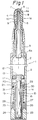
- Fig. 1 to 3 show the applicator 1 having an end portion 1a for applying a fluid according to the first embodiment of the present invention.
- the applicator 1 comprises a barrel including a main barrel 2 having a reservoir 12 for containig a fluid such as cream eye shadow therein and an end barrel 3 firmly secured by main barrel 2.
- the end portion 1a of the applicator 1 comprises a tubular core 4 having a conduit 6 extending along the longitudinal axis of the tubular core 4, and an elastic porous outer membrane 5 covering the tip of the tubular core 4 of the tubular core 4.
- the tubular core 4 has an inlet 6a and an outlet 7, and is attached to the main barrel 2 so that the inlet 6a of the conduit 6 receives a fluid in the reservoir 12.
- the end barrel 3 encloses the outer membrane 5 so that the tip of the outer membrane 5 projects from the end barrel 3. It is possible to detachably arrange a cap (not shown) on the end barrel 3 to protect the outer membrane 5.
- the tubular core 4 has a tip in a generally rounded shape.
- the tip of the tubular core 4 is cut out along a plane 4a inclined to the longitudinal axis of the tubular core 4, so that the outlet 7 of the conduit 6 opens on one side of the tubular core 4 from the longitudinal axis thereof.
- the outer membrane 5 is made from a porous material in the form of a bag.
- the outer membrane 5 comprises three porous sheet members 8 to 10.
- the first porous sheet members 8 comprises a urethane foam having a relatively large porosity and constitutes one half of the outer membrane 5 arranged on one side of the outer membrane 5 so as to cover the outlet 7 of the conduit 6 of the tubular core 4.
- the third porous sheet member 10 covers or overlaps the second porous sheet member 9, and the second and third porous sheet members 9 and 10 constitute one half of the outer membrane 5 arranged on the outer side of the outer membrane 5.
- the second porous sheet member 9 comprises a urethane foam having a porosity generally identical to that of the first porous sheet member 8 and the third porous sheet member 10 comprises a urethane foam having a relatively small porosity and thus a high density so that a fluid does not easily soak through the third porous sheet member 10.
- the third porous sheet member 10 is adhered to the second porous sheet member 9 by heating and welding adjoining portions of the second and third porous sheet members 9 and 10 together.
- the first porous sheet members 8 is adhered to the second and third porous sheet members 9 and 10 by heating and welding adjoining portions thereof together.
- the first porous sheet member 8 allowing a fluid to soak therethrough bears a different color from a color of the third porous sheet member 10 not allowing a fluid to soak therethrough, so that a user can visually recognize one from the other.
- the first porous sheet member 8 is colored black
- the third porous sheet member 10 is colored white.
- the three porous members 8 to 10 are made from the same kind of material in this embodiment, but it is possible to make the three porous sheet members 8 to 10 from different materials other than a urethane foam.
- silicone sponge, NBR sponge, non-woven fabric, felt, woven fabric and paper can be used for the porous sheet members 8 to 10.
- the outer membrane 5 can be formed from a plurality of porous sheet members 8 to 10 having different porosities, as described above, but it is possible to form the outer membrane 5 from a single porous material through which a fluid can soak.
- a material for the third porous sheet members 10 is more permeable that the first and second porous sheet members 8 and 9.
- a small aperture 11 is provided in the first porous sheet member 8 of the outer membrane 5 so that a fluid can soak through the first porous sheet members 8 via the small aperture 11.
- the small aperture 11 opens toward the outlet 7 of the conduit 6.
- the small aperture 11 can be provided by piercing a pin in the first porous sheet member 8 to break a portion of the member 8 to form a hole, or by piercing a hot pin in the first porous sheet member 8 to dissolve a portion of the member 8 to form a hole. Accordingly, a fluid can soak through both the small aperture 11 and the porous wall of the first porous sheet member 8 of the outer membrane 5. A fluid can soak through the small aperture 11 when the porous wall of the first porous sheet member 8 of the outer membrane 5 is clogged.
- the outer membrane 5 is pinched between the tubular core 4 and the end barrel 3.
- the tubular core 4 has an externally projecting annular shoulder 33
- the end barrel 3 has an internally projecting annular shoulder 34 arranged in the opposite sense to the externally projecting annular shoulder 33 of the tubular core 4, i.e., the internally projecting annular shoulder 34 faces the externally projecting annular shoulder 33 with a small gap between the edge of the internally projecting annular shoulder 34 and the edge of externally projecting annular shoulder 33, as shown in Fig. 2.
- the outer membrane 5 can be thus pinched by the externally projecting annular shoulder 33 of the tubular core 4 and the internally projecting annular shoulder 34 of the end barrel 2 betwen the edges thereof.
- the tubular core 4 has external annular projection 35
- the end barrel 3 has an internal annular projection 36 at a position axially offset from the external annular projection 35.
- the outer membrane 5 can be reliably fastened to the tubular core 4 without other fastening means.
- Fig. 30 to 32 Modifications of the shoulders and/or the projections are shown in Fig. 30 to 32.
- the tubular core 4 has an externally projecting annular shoulder 33, and the end barrel 3 has an internally projecting annular shoulder 34.
- the tubular core 4 has an external annular projections 35, and the end barrel 3 has internal annular projections 36 and 37 so that the outer membrane 5 is thus piched in a wavy position.
- the tubular core 4 has an externally projecting annular shoulder 33, and the barrel 3 has an internally projecting annular shoulder 34. Also, the tubular core 4 has an external annular projection 35, and the end barrel 3 has an internal annular projection 36 at a position axially overlapping the exernal annular projection 35.
- tubular core 4 has an externally projecting annular shoulder 33
- end barrel 3 has an inernally projecting annular shoulder 34 to pinch the outer membrane 5 therebetween.
- a piston 13 is slidably arranged in the reservoir 12 of the main barrel 2, and a rod 16 is connected to the rear of the piston 13.
- the rod 16 has a male thereas 14 along the length thereof and a pair of flat surfaces 15.
- a nut-like support element 17 having a female thread 18 is arranged in the main barrel 2, the support element 17 being axially and rotationally immovable.
- the rod 16 is inserted in the support element 17 with the male thread 14 engaging with the female thread 18. Accordingly, the rod 16 with the piston 13 advances in the main barrel 2 to discharge a fluid in the reservoir 12 through the conduit 6 of the tubular core 4 when the rod 16 is rotated.
- a rotatable hollow actuating rod 19 is inserted in the main barrel 2 and over the rod 16.
- the actuating rod 19 has a flange 20 at the front end of the actuating rod 19, a ratchet 21 on the rear surface of the flange 20, a pair of inner flat surfaces 22 for engagement with the flat surfaces 15 of the rod 16 for conjoint rotation of the actuating rod 19 and the rod 16, and an outer polygonal profile 23.
- a manually operable tail cap 24 is attached to the rear end of the main barrel 2, the tail cap 24 having an inner polygonal profile adapted to fit on the outer polygonal profile 23 of the actuating rod 19 for conjoint rotation of the tail cap 24 and the actuating rod 19.
- the tail cap 24 has a split ring portion 27 with slits 26, and a flange 28 at the front end of the split ring portion 27.
- the split ring portion 27 is elastically forced into a retaining ring 25 fixed in the main barrel 2 and the flange 28 engages with the inner edge of the retaining ring 25 to retain the tail cap 24 to the main barrel 2 while allowing the rotation of the tail cap 24 relative to the main barrel 2.
- a nut-like spring support 30 is inserted in the main barrel and over the actuating rod 19, and a spring 31 is arranged between the spring support 30 and the retaining ring 25.
- the spring support 30 is rotationally immovable but axially mavable.
- the spring support 30 is urged toward the flange 20 of the actuating rod 19 by the spring 31, and has a ratchet 29 which cooperates with the ratchet 21 of the flange 20 of the actuating rod 19.
- the spring support 30 axially moves apart from the flange 20 when the actuating rod 19 is rotated in one direction and the teeth of the ratchet 21 of the latter move beyond the teeth of the ratchet 29 of the spring support 30.
- the ratchets 21 and 29 allow the actuating rod 19 and the tail cap 24 to rotate in one direction only.
- Figs. 4 to 6 show the applicator 1 according to another embodiment of the present invention.
- the applicator 1 comprises, similar to the first embodiment, a tubular core 4 having a conduit 6 with an inlet 6a and an outlet 7, and an elastic porous outer membrane 5 covering the tip of the tubular core 4.
- the tip of the tubular core 4 is cut out along a plane 4a inclined to a longitudinal axis of the tubular core 4, so that the outlet 7 of the conduit 6 opens on one side of the tubular core 4 from the longitudinal axis thereof.
- the outer membrane 5 is made from single porous material in the form of a bag.
- the tip portion of the tubular core 4 has a generally oval cross-section with a pair of opposite larger curvature portions and a pair of opposite smaller curvature portions between the larger curvature portions, as shown in Figs. 4 and 6.
- the outlet 7 of the conduit 6 opens to one of the larger curvature portions, as shown in Figs. 5 and 6. Accordingly, a fluid soaks through the outer membrane 5 at the inclined surfaces thereof on one side ot the tubular core 4, as indicated by the character S in Fig. 4.
- the applicator 1 also includes a reservoir 12 in the main barrel 2, a piston 13, and supporting and actuating members similar to those of Fig. 1 and 2.
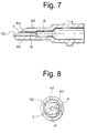
- the tip portion of the tubular core 4 has a pair of flat outer surfaces 4f and the outlet 7 of the conduit 6 opens to one of the flat outer surfaces 4f.
- the conduit 6 extends straight through the tubular core 4, similar to that of the previous embodiment.
- the tip of the tubular core 4 is cut out along a plane 4b passing the longitudinal axis of the tubular core 4, and then along a plane 4a inclined to the longitudinal axis of the tubular core 4, to form the outlet 7.
- the tip portion of the tubular core 4 has a pair of flat outer surfaces 4f and the outlet 7 of the conduit 6 opens to one of flat outer surfaces.
- the edges of the flat outer surfaces 4f are chamfered.
- the tip of the tubular core 4 is cut out along a plane 4b passing the longitudinal axis of the tubular core 4, and then along a plane 4a inclined to the longitudinal axis of the tubular core 4, to form the outlet 7.
- the cut out portions along the plane 4b is longer than that of Fig. 7 and 8.
- the tip portion of the tubular core 4 has an oval profile, similar to that of Fig. 5 and 6,
- a wall 4g is provided at a distal end of the tubular core 4 past the outlet 7 to block one half of the conduit 6.
- the tip of the tubular core 4 is cut out along a plane 4b passing the longitudinal axis of the tubular core 4, and then along a plane 4a inclined to the longitudinal axis of the tubular core 4, to form the outlet 7.
- the tip portion of the tubular core 4 has pair of flat surfaces 4f, similar to those of Figs. 7 and 8.
- a wall 4g is provided at a distal end of the tubular core 4 past the outlet 7 to block one half of the conduit 6.
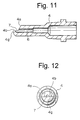
- the tip of the tubular core 4 is cut out along a plane 4a inclined to the longitudinal axis of the tubular core 4 and passing through the top of the wall 4g, to form the outlet 7.
- the tip portion of the tubular core 4 has a pair of flat surfaces 4f, similar to those of Figs, 10 and 11.
- a wall 4g is provided at a distal end of the tubular core 4 past the outlet 7 to block one half of the conduit 6.
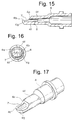
- the tip of the tubular core 4 is cut out along a plane 4b passing the longitudinal axis of the tubular core 4, and then along a plane 4a inclined to the longitudinal axis to the tubular core 4, to form the outlet 7.
- tubular core 4 is similar to that of Figs. 11 and 12, but this tubular core 4 has a recess 40 arranged in the conduit 6 of the tubular core 4 near the outlet 7 for holding a fluid therein.
- tubular core 4 is similar to that of Figs. 13 and 14, but this tubular core 4 has a recess 40 arranged in the conduit 6 of the tubular core 4 near the outlet 7 for holding a fluid therein.
- tubular core 4 is similar to that of Figs. 15 and 16, but this tubular core 4 has a recess 40 arranged in the conduit 6 of the tubular core 4 near the outlet 7 for holding a fluid therein.
- tubular core 4 is generally similar to that of Figs. 15 and 16, but an outer shape of the tubular core 4 is gradually reduced toward a distal end of the tubular core 4.
- a recess 42 for containing a fluid is provided by drilling the inclined wall in the direction perpendicular to the longitudinal axis of the tubular core 4.
Landscapes
- Coating Apparatus (AREA)
- Media Introduction/Drainage Providing Device (AREA)
Description
- Fig. 1
- is a cross-sectional view of the applicator embodiment of the present invention;
- Fig. 2
- is an enlarged cross-sectional view of a portion of the applicator of Fig. 1;
- Fig. 3
- is an exploded perspective view of the barrel of the applicator and elements housed in the barrel of Figs. 1 and 2;
- Fig. 4
- is a perspective view of the applicator of Fig. 1;
- Fig. 5
- is a cross-sectional view of the tubular core of Fig. 1;
- Fig. 6
- is a front view of the tubular core of Fig. 5, viewed from the arrow VII in Fig. 5;
- Fig. 7
- is a cross-sectional view similar to Fig. 5, but illustrating the tubular core of the first modified example;
- Fig. 8
- is a front view of the tubular core of Fig. 7;
- Fig. 9
- is a cross-sectional view similar to Fig. 5, but illustrating the tubular core of the second modified example;
- Fig. 10
- is a front view of the tubular core of Fig. 9;
- Fig. 11
- is a cross-sectional view similar to Fig. 5, but illustrating the tubular core of the third modified example;
- Fig. 12
- is a front view of the tubular core of Fig. 11;
- Fig. 13
- is a cross-sectional view similar to Fig. 5, but illustrating the tubular core of the fourth modified example;
- Fig. 14
- is a front view of the tubular core of Fig. 15;
- Fig. 15
- is a cross-sectional view similar to Fig. 5, but illustrating the tubular core of the fifth modified example;
- Fig. 16
- is a front view of the tubular core of Fig. 15;
- Fig. 17
- is a perspective view of the tubular core of Fig. 15;
- Fig. 18
- is a cross-sectional view similar to Fig. 5, but illustrating the tubular core of the sixth modified example;
- Fig. 19
- is a front view of the tubular core of Fig. 18;
- Fig. 20
- is a cross-sectional view similar to the Fig. 5, but illustrating the tubular core of the seventh modified example;
- Fig. 21
- is a front view of the tubular core of Fig. 20;
- Fig. 22
- is a cross-sectional view similar to Fig. 5, but illustrating the tubular core of the seventh modified example;
- Fig. 23
- is a front view of the tubular core of Fig. 22;
- Fig. 24
- is a cross-sectional view similar to Fig. 5, but illustrating the tubular core of the eighth modified example;
- Fig. 25
- is a front view of the tubular core of Fig. 24;
- Fig. 26
- is a perspective view of the tubular core of Fig. 24;
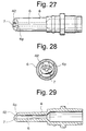
- Fig. 27
- is a plan view of the tubular core of the ninth modified example;
- Fig. 28
- is a front view of the tubular core of Fig. 27;
- Fig. 29
- is a cross-sectional view of the tubular core of Fig. 27;
- Fig. 30
- is a cross-sectional view of a portion of the modified applicator, including means for fastening the outer membrane to the tubular core;
- Fig. 31
- is a cross-sectional view of a portion of the modified applicator;
- Fig. 32
- is a cross-sectional view of a portion of the modified applicator.
Claims (20)
- An applicator (1) for applying a fluid comprising:a tubular core (4) having a longitudinal axis, a generally rounded tip, and a conduit (6) extending along the longitudinal axis, the conduit (6) having an inlet (6a) adapted to receive a fluid and an outlet (7);a porous outer membrane (5) permeable to a fluid and arranged to cover at least a portion of the tubular core (4) including the outlet (7) of the conduit (6); wherein the outer membrane (5) includes an aperture (11) and wherein the outlet (7) of the conduit (6) of the tubular core (4) is formed by cutting out a portion of the tubular core (4) along a plane (4a) inclined to the longitudinal axis,
characterized in that the cut out portion of the tubular core (4) is arranged on one side of the longitudinal axis only, that the surface of the other side of the tubular core is rounded, that the aperture (11) is provided on the side of the tubular core (4) corresponding to the side where the outlet (7) is formed and that the aperture (11) is inclined to the longitudinal axis of the tubular core (4). - An applicator according to claim 1, wherein a recess (40) is arranged in the conduit (6) of the tubular core (4) near the outlet (7) for holding a fluid therein.
- An applicator according to claim 1, wherein the tubular core (4) has a generally oval cross-section with a pair of opposite larger curvature portions and a pair of opposite smaller curvature portions between the larger curvature portions, and the outlet (7) of the conduit (6) opens to one of the larger curvature portions.
- An applicator according to claim 1, wherein the tubular core (4) has a pair of flat outer surfaces (4f), and the outlet (7) of the conduit (6) opens to one of the flat outer surfaces (4f)
- An applicator according to claim 1, wherein the conduit (6) extends straight through the tubular core (4).
- An applicator according to claim 1, wherein a wall (4g) is provided at a distal end of the tubular core (4) past the outlet (7) to block the conduit (6).
- An applicator according to claim 1, wherein an outer shape of the tubular core (4) is gradually reduced toward a distal end of the tubular core (4).
- An applicator according to claim 1, further comprising a barrel (2) having a reservoir (12) adapted to contain a fluid therein, wherein the tubular core (4) is attached to the barrel (2) so that the inlet (6a) of the conduit (6) receives a fluid in the reservoir (12).
- An applicator according to claim 8, further comprising a piston (13) arranged in the reservoir (12) of the barrel (2), and actuating means for actuating the piston (13) to discharge a fluid in the reservoir (12) through the conduit (6) of the tubular core (4).
- An applicator according to claim 9, wherein said actuating means comprises a manually operable member (19,24) which can be rotatably operated to advance the piston (13).
- An applicator according to claim 10, wherein ratchet means (21,29) is provided to allow the manually operable member (19,24) to rotate in one direction only.
- An applicator according to claim 8, wherein the barrel comprises a main barrel (2) and an end barrel (3) attached to the main barrel (3), the tubular core (4) being attached to the main barrel (2) with the end barrel (3) enclosing the tubular core (4) so that a portion of the outer membrane (5) covering the outlet (7) of the conduit (6) projects from the end barrel (3).
- An applicator according to claim 12, wherein the outer membrane (5) is pinched between the tubular core (4) and the end barrel (3).
- An applicator according to claim 13, wherein the tubular core (4) has an externally projecting annular shoulder (33), and the end barrel (3) has an internally projecting annular shoulder (34) arranged in the opposite sense to the externally projecting annular shoulder (33) of the tubular core (4), whereby the outer membrane (5) is pinched by the externally projecting annular shoulder (33) of the tubular core (4) and the internally projecting annular shoulder (34) of the end barrel (3).
- An applicator according to claim 13, wherein the tubular core (4) has at least one external annular projection (35), and the end barrel (3) has at least one internal annular projection (36,37) at a position axially offset from the at least one external annular projection (35), whereby the outer membrane (5) is pinched in a wavy configuration by the at least one external annular projection (35) and the at least one internal annular projection (36,37).
- An applicator according to claim 14, wherein the tubular core (4) has at least one external annular projection (35), and the end barrel (3) has at least one internal annular projection (36,37) at a position axially overlapping the at least one external annular projection (35) whereby the outer membrane (5) is pinched by the at least one external annular projection (35) and the at least one internal annular projection (36,37).
- An applicator according to claim 1, wherein the outer membrane (5) comprises at least two porous sheet members having different porosities from each other.
- An applicator according to claim 17, wherein one of the at least two porous sheet members having a larger porosity is arranged on one side of the outer membrane to cover the outlet, and the other porous sheet member is arranged on the other side of the outer membrane.
- An applicator according to claim 17, wherein the at least two porous sheet members comprises three porous sheet members (8,9,10), the first of three porous sheet members (8) is arranged on one side of the outer membrane (5) to cover the outlet (7), and the second and the third of three porous sheet members (9,10) are arranged on the other side of the outer membrane (5) with the third porous sheet member (10) covering the second porous sheet member (9), the third porous sheet member (10) having the smallest porosity.
- An applicator according to claim 1, wherein the small aperture (11) is formed by piercing a pin in the outer membrane (5).
Applications Claiming Priority (2)
| Application Number | Priority Date | Filing Date | Title |
|---|---|---|---|
| JP1993026813U JP2603088Y2 (en) | 1993-04-23 | 1993-04-23 | Fluid application member |
| JP26813/93U | 1993-04-23 |
Publications (2)
| Publication Number | Publication Date |
|---|---|
| EP0620989A1 EP0620989A1 (en) | 1994-10-26 |
| EP0620989B1 true EP0620989B1 (en) | 1998-11-04 |
Family
ID=12203732
Family Applications (1)
| Application Number | Title | Priority Date | Filing Date |
|---|---|---|---|
| EP93121167A Expired - Lifetime EP0620989B1 (en) | 1993-04-23 | 1993-12-31 | An applicator for a fluid having a porous membrane |
Country Status (4)
| Country | Link |
|---|---|
| US (1) | US5454660A (en) |
| EP (1) | EP0620989B1 (en) |
| JP (1) | JP2603088Y2 (en) |
| DE (1) | DE69321943T2 (en) |
Families Citing this family (37)
| Publication number | Priority date | Publication date | Assignee | Title |
|---|---|---|---|---|
| US6196747B1 (en) | 1995-12-21 | 2001-03-06 | Creative Packaging Corp. | Product dispensing cover |
| US5851079A (en) * | 1996-10-25 | 1998-12-22 | The Procter & Gamble Company | Simplified undirectional twist-up dispensing device with incremental dosing |
| USD408592S (en) * | 1997-10-06 | 1999-04-20 | Revlon Consumer Products Corporation | Cosmetic dispenser |
| US6036391A (en) * | 1997-12-19 | 2000-03-14 | Prestone Products Corporation | Hand-held applicator for applying a cleaning or polishing solution to a surface |
| USD416112S (en) | 1998-03-06 | 1999-11-02 | Prestone Products Corporation | Hand-held applicator for applying a cleaning or polishing solution to a surface |
| JP3081834B2 (en) * | 1998-03-20 | 2000-08-28 | 三菱鉛筆株式会社 | Liquid applicator |
| USD416356S (en) | 1998-09-28 | 1999-11-09 | The Procter & Gamble Company | Container |
| US6585511B2 (en) * | 2001-07-16 | 2003-07-01 | Centrix, Inc. | Dental material container with porous flow through applicator |
| US6474891B1 (en) * | 2001-11-29 | 2002-11-05 | Ming Hsiung Liu | Structure of a make-up pen |
| DE10241218A1 (en) * | 2002-09-06 | 2004-03-25 | Geka Brush Gmbh | Storage and applicator unit |
| US7309184B2 (en) * | 2003-08-15 | 2007-12-18 | Revlon Consumer Products Corporation | Dispenser for fluid materials |
| USD562561S1 (en) | 2004-06-07 | 2008-02-26 | Hct Limited | Twist up pen type dispenser with brush applicator |
| US7201527B2 (en) * | 2004-07-30 | 2007-04-10 | Hct Limited | Twist up pen type dispenser with brush applicator |
| JP2006068297A (en) * | 2004-09-02 | 2006-03-16 | Tokiwa Corp | Applicator |
| US7144174B2 (en) * | 2004-12-30 | 2006-12-05 | Unilever Home & Personal Care Usa Division Of Conopco, Inc. | Applicator for liquid cosmetic compositions |
| US7745683B2 (en) * | 2005-04-16 | 2010-06-29 | Aalnex, Inc. | Deformable and conformable wound protecting apparatus and its method of application |
| EP1946671A4 (en) | 2005-11-09 | 2011-03-02 | Mitsubishi Pencil Co | Liquid applicator |
| AR056792A1 (en) * | 2005-11-12 | 2007-10-24 | Unilever Nv | HAIR DISPENSER |
| JP4387365B2 (en) | 2006-03-07 | 2009-12-16 | 三菱鉛筆株式会社 | Liquid applicator |
| JP4932332B2 (en) * | 2006-05-31 | 2012-05-16 | 株式会社 資生堂 | Viscous cosmetics |
| KR100789290B1 (en) * | 2006-09-28 | 2007-12-28 | 변영광 | Tubular Liquid Cosmetic Container |
| KR100840555B1 (en) * | 2006-12-08 | 2008-06-23 | 권혁탁 | Nozzle tip of cosmetic container with vacuum cutoff |
| US20080142406A1 (en) * | 2006-12-18 | 2008-06-19 | Spatz Laboratories | Flexible cosmetic applicator |
| JP5037197B2 (en) * | 2007-04-02 | 2012-09-26 | 三菱鉛筆株式会社 | Liquid applicator |
| JP5164485B2 (en) * | 2007-09-10 | 2013-03-21 | 三菱鉛筆株式会社 | Liquid cosmetic applicator |
| JP5152661B2 (en) * | 2008-08-22 | 2013-02-27 | 株式会社竹宝堂 | Tip with face shaft |
| US20100247225A1 (en) * | 2009-03-30 | 2010-09-30 | Jun Zhang | Cosmetic applying device |
| MX2012002476A (en) | 2009-09-16 | 2012-03-26 | Colgate Palmolive Co | Oral care system, kit and method. |
| MX2012006221A (en) | 2009-12-23 | 2012-07-03 | Colgate Palmolive Co | SYSTEM FOR ORAL CARE. |
| EP2515699B1 (en) | 2009-12-23 | 2014-08-06 | Colgate-Palmolive Company | Oral care system |
| KR101453632B1 (en) | 2009-12-23 | 2014-10-22 | 콜게이트-파아므올리브캄파니 | Oral care system |
| PH12012500882A1 (en) | 2009-12-23 | 2013-01-07 | Colgate Palmolive Co | Oral care system, kit and method |
| EP2810584A3 (en) | 2010-12-15 | 2015-02-25 | Colgate-Palmolive Company | Oral care dispenser and system using the same |
| KR20140022878A (en) * | 2011-05-23 | 2014-02-25 | 도쿄 야쿠힌 고교 가부시키가이샤 | Application container |
| JP6670539B2 (en) * | 2014-06-13 | 2020-03-25 | 三菱鉛筆株式会社 | Applicator |
| FR3029089B1 (en) * | 2014-12-02 | 2018-03-02 | L'oreal | DEVICE FOR CONDITIONING AND APPLYING EYELINER |
| US20230024451A1 (en) * | 2021-07-13 | 2023-01-26 | Xavier Dillard | Enhanced gradient marker creating various tones |
Family Cites Families (17)
| Publication number | Priority date | Publication date | Assignee | Title |
|---|---|---|---|---|
| US1968686A (en) * | 1931-09-11 | 1934-07-31 | A J & K Company Inc | Cream dispenser |
| US2724850A (en) * | 1954-12-30 | 1955-11-29 | Howard Walter | Fountain applicator for dispensing liquids |
| US2948008A (en) * | 1957-04-29 | 1960-08-09 | Leeds & Micallef | Dispensing containers |
| US2962743A (en) * | 1957-12-10 | 1960-12-06 | United Shoe Machinery Corp | Shoe cream applicators with laminated plastic sponge pads |
| US3010138A (en) * | 1959-11-06 | 1961-11-28 | Nadai Alexander | Dispenser device for viscous fluids |
| CH507134A (en) * | 1969-06-23 | 1971-05-15 | Fritz Victor | Distributor attachment on a spray can |
| FR2030798A5 (en) * | 1969-12-08 | 1970-11-13 | Schwartzman Gilbert | |
| US4002182A (en) * | 1974-10-09 | 1977-01-11 | Aubrey Jonathan Michel | Device for storing and applying cosmetics |
| DE3430582A1 (en) * | 1984-08-20 | 1986-02-27 | geb. Verges Karin 3052 Bad Nenndorf Dahm | DEVICE FOR APPLICATION OF PEN-SHAPED COSMETICS |
| JPS629579A (en) * | 1985-07-05 | 1987-01-17 | Daiichi Kasei Kk | Tape guide |
| JPS6382479U (en) * | 1986-11-13 | 1988-05-30 | ||
| US4889441A (en) * | 1988-04-11 | 1989-12-26 | Janell Tice | Skin lotion dispenser and applicator |
| FR2645724A1 (en) * | 1989-04-13 | 1990-10-19 | Petit Kenneth | Telescopic applicator for a fluid product to be applied to the body and, particularly, to the back |
| JPH07111733B2 (en) * | 1989-09-22 | 1995-11-29 | 富士写真フイルム株式会社 | Method and apparatus for energy subtraction of radiation image |
| JPH086548Y2 (en) * | 1989-12-25 | 1996-02-28 | 三菱鉛筆株式会社 | Fluid applicator |
| JPH0480409A (en) * | 1990-07-23 | 1992-03-13 | Komatsu Ltd | Marking on road and detection method thereof |
| JPH0637771Y2 (en) * | 1990-11-22 | 1994-10-05 | 三菱鉛筆株式会社 | Pen core for applying fluid applicator |
-
1993
- 1993-04-23 JP JP1993026813U patent/JP2603088Y2/en not_active Expired - Fee Related
- 1993-12-31 EP EP93121167A patent/EP0620989B1/en not_active Expired - Lifetime
- 1993-12-31 DE DE69321943T patent/DE69321943T2/en not_active Expired - Fee Related
-
1994
- 1994-01-04 US US08/177,513 patent/US5454660A/en not_active Expired - Fee Related
Also Published As
| Publication number | Publication date |
|---|---|
| JP2603088Y2 (en) | 2000-02-14 |
| JPH0679420U (en) | 1994-11-08 |
| DE69321943D1 (en) | 1998-12-10 |
| US5454660A (en) | 1995-10-03 |
| EP0620989A1 (en) | 1994-10-26 |
| DE69321943T2 (en) | 1999-04-01 |
Similar Documents
| Publication | Publication Date | Title |
|---|---|---|
| US5454660A (en) | Applicator having a porous membrane with aperture | |
| US4993437A (en) | Hair cosmetics coating tool | |
| JP2815334B2 (en) | Capillary applicator with end slit | |
| US5568669A (en) | Lotion applicator | |
| US5000199A (en) | Arrangement for applying a foam-type hair care lotion | |
| WO2004039316A3 (en) | Hair colorant dispenser | |
| US4031909A (en) | Dental floss holder and dispenser | |
| US5937864A (en) | Hair coloring applicator with mixing chamber | |
| CA2035908A1 (en) | Liquid applicator | |
| JPS63189105A (en) | Hair dyeing instrument | |
| ES8608836A1 (en) | Stick-type device for applying cosmetic materials. | |
| US6390101B1 (en) | Self-contained applicator for applying fluid | |
| CA2040754A1 (en) | Liquid hair cosmetic painting instrument | |
| EP3840820B1 (en) | Multifunctional pencil for eyebrow styling | |
| KR200297649Y1 (en) | Cloth used for wrapping cut | |
| ES1034588U (en) | Hair treatment comb | |
| JP3884587B2 (en) | Liquid applicator | |
| CA2040719A1 (en) | Liquid hair cosmetic applicator | |
| US6125858A (en) | Writing instrument dental device attachment | |
| KR200224635Y1 (en) | A cosmetic pencil for eyeshadowing | |
| JPH08323065A (en) | Portable razor | |
| JPH11169224A (en) | Hair applicator | |
| US20040086317A1 (en) | Holder for releasably holding conventional cosmetic tools | |
| US20050098189A1 (en) | Apparatus and method for coloring skin | |
| KR200192472Y1 (en) | Comb with spray |
Legal Events
| Date | Code | Title | Description |
|---|---|---|---|
| PUAI | Public reference made under article 153(3) epc to a published international application that has entered the european phase |
Free format text: ORIGINAL CODE: 0009012 |
|
| 17P | Request for examination filed |
Effective date: 19940127 |
|
| AK | Designated contracting states |
Kind code of ref document: A1 Designated state(s): DE FR GB IT |
|
| 17Q | First examination report despatched |
Effective date: 19961018 |
|
| GRAG | Despatch of communication of intention to grant |
Free format text: ORIGINAL CODE: EPIDOS AGRA |
|
| GRAG | Despatch of communication of intention to grant |
Free format text: ORIGINAL CODE: EPIDOS AGRA |
|
| GRAH | Despatch of communication of intention to grant a patent |
Free format text: ORIGINAL CODE: EPIDOS IGRA |
|
| GRAH | Despatch of communication of intention to grant a patent |
Free format text: ORIGINAL CODE: EPIDOS IGRA |
|
| GRAA | (expected) grant |
Free format text: ORIGINAL CODE: 0009210 |
|
| AK | Designated contracting states |
Kind code of ref document: B1 Designated state(s): DE FR GB IT |
|
| PG25 | Lapsed in a contracting state [announced via postgrant information from national office to epo] |
Ref country code: IT Free format text: LAPSE BECAUSE OF FAILURE TO SUBMIT A TRANSLATION OF THE DESCRIPTION OR TO PAY THE FEE WITHIN THE PRE;WARNING: LAPSES OF ITALIAN PATENTS WITH EFFECTIVE DATE BEFORE 2007 MAY HAVE OCCURRED AT ANY TIME BEFORE 2007. THE CORRECT EFFECTIVE DATE MAY BE DIFFERENT FROM THE ONE RECORDED.SCRIBED TIME-LIMIT Effective date: 19981104 |
|
| REF | Corresponds to: |
Ref document number: 69321943 Country of ref document: DE Date of ref document: 19981210 |
|
| PG25 | Lapsed in a contracting state [announced via postgrant information from national office to epo] |
Ref country code: GB Free format text: LAPSE BECAUSE OF NON-PAYMENT OF DUE FEES Effective date: 19990204 |
|
| ET | Fr: translation filed | ||
| PLBE | No opposition filed within time limit |
Free format text: ORIGINAL CODE: 0009261 |
|
| STAA | Information on the status of an ep patent application or granted ep patent |
Free format text: STATUS: NO OPPOSITION FILED WITHIN TIME LIMIT |
|
| GBPC | Gb: european patent ceased through non-payment of renewal fee |
Effective date: 19990204 |
|
| 26N | No opposition filed | ||
| PGFP | Annual fee paid to national office [announced via postgrant information from national office to epo] |
Ref country code: DE Payment date: 20010123 Year of fee payment: 8 |
|
| PGFP | Annual fee paid to national office [announced via postgrant information from national office to epo] |
Ref country code: FR Payment date: 20011107 Year of fee payment: 9 |
|
| PG25 | Lapsed in a contracting state [announced via postgrant information from national office to epo] |
Ref country code: DE Free format text: LAPSE BECAUSE OF NON-PAYMENT OF DUE FEES Effective date: 20020702 |
|
| PG25 | Lapsed in a contracting state [announced via postgrant information from national office to epo] |
Ref country code: FR Free format text: LAPSE BECAUSE OF NON-PAYMENT OF DUE FEES Effective date: 20030901 |
|
| REG | Reference to a national code |
Ref country code: FR Ref legal event code: ST |