EP0620900B1 - Torque control clutch - Google Patents
Torque control clutch Download PDFInfo
- Publication number
- EP0620900B1 EP0620900B1 EP92920471A EP92920471A EP0620900B1 EP 0620900 B1 EP0620900 B1 EP 0620900B1 EP 92920471 A EP92920471 A EP 92920471A EP 92920471 A EP92920471 A EP 92920471A EP 0620900 B1 EP0620900 B1 EP 0620900B1
- Authority
- EP
- European Patent Office
- Prior art keywords
- cam
- clutch
- shaft
- torque control
- cam shaft
- Prior art date
- Legal status (The legal status is an assumption and is not a legal conclusion. Google has not performed a legal analysis and makes no representation as to the accuracy of the status listed.)
- Expired - Lifetime
Links
Images


Classifications
-
- B—PERFORMING OPERATIONS; TRANSPORTING
- B25—HAND TOOLS; PORTABLE POWER-DRIVEN TOOLS; MANIPULATORS
- B25B—TOOLS OR BENCH DEVICES NOT OTHERWISE PROVIDED FOR, FOR FASTENING, CONNECTING, DISENGAGING, OR HOLDING
- B25B23/00—Details of, or accessories for, spanners, wrenches, screwdrivers
- B25B23/14—Arrangement of torque limiters or torque indicators in wrenches or screwdrivers
- B25B23/145—Arrangement of torque limiters or torque indicators in wrenches or screwdrivers specially adapted for fluid operated wrenches or screwdrivers
-
- F—MECHANICAL ENGINEERING; LIGHTING; HEATING; WEAPONS; BLASTING
- F16—ENGINEERING ELEMENTS AND UNITS; GENERAL MEASURES FOR PRODUCING AND MAINTAINING EFFECTIVE FUNCTIONING OF MACHINES OR INSTALLATIONS; THERMAL INSULATION IN GENERAL
- F16D—COUPLINGS FOR TRANSMITTING ROTATION; CLUTCHES; BRAKES
- F16D43/00—Automatic clutches
- F16D43/02—Automatic clutches actuated entirely mechanically
- F16D43/20—Automatic clutches actuated entirely mechanically controlled by torque, e.g. overload-release clutches, slip-clutches with means by which torque varies the clutching pressure
- F16D43/202—Automatic clutches actuated entirely mechanically controlled by torque, e.g. overload-release clutches, slip-clutches with means by which torque varies the clutching pressure of the ratchet type
- F16D43/204—Automatic clutches actuated entirely mechanically controlled by torque, e.g. overload-release clutches, slip-clutches with means by which torque varies the clutching pressure of the ratchet type with intermediate balls or rollers
- F16D43/208—Automatic clutches actuated entirely mechanically controlled by torque, e.g. overload-release clutches, slip-clutches with means by which torque varies the clutching pressure of the ratchet type with intermediate balls or rollers moving radially between engagement and disengagement
Definitions
- This invention relates generally to torque control shutoff clutches for power tools and the like as disclosed e.g. in GB-A-1 213 948 and more particularly to a controlled fluid shutoff and reset mechanism for a fluid operated tool.
- Fluid operated tools for driving fasteners and the like typically incorporate a rotary vane air motor to drive a rotary shaft connected to a tool bit.
- Such tools are often equipped with a clutch mechanism that responds to the torque imparted by the tool to the fastener. When a specific torque is reached, the clutch mechanism automatically decouples the motor from the tool bit and terminates further tool output to the fastener.
- decoupling and shutoff occur as cleanly and as closely as possible to a desired applied torque. If the motor is not decoupled there occurs substantial inertial followup which may overtighten the fastener and lead to greater torque reaction on the operator. If the motor is not shut off upon clutch release it will continue to run without accomplishing useful work until the operator shuts it off.
- a torque control clutch of the type comprising a rotary driven clutch shaft element having a stepped axial bore adapted to be driven at one end of a motor; an output clutch spindle mounted for rotation within said stepped axial bore; a cam shaft mounted in said axial bore for both rotation and reciprocation along the axis of said axial bore; said cam shaft being capable of axially reciprocating in response to the rotational position of said cam shaft in said bore; and a means is provided for selectively coupling said cam shaft to said output clutch spindle for rotation of said output clutch spindle in response to the axial position of said cam shaft relative to said clutch shaft, and characterised in that a cylindrical cam block is rotatably disposed within said axial bore of said clutch shaft for selectively rotatably engaging said cam shaft to resist relative rotation of said cam shaft in said axial bore during a selected torque rise and thereafter assisting rotation of said cam shaft once a selected torque level is achieved to cause longitudinal reciprocation of said cam shaft.
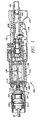
- the present torque control clutch is shown embodied in a pneumatic nutrunner generally indicated by reference numeral 100.
- the exterior of the tool has a handle 101, a motor housing 108 and a clutch housing 111.
- the handle 101 is provided with an air inlet 103 leading to an inlet air passage 102 which in turn provides pneumatic pressure fluid or air to a manually operated tilt valve 105.
- the tilt valve 105 is operated by a throttle lever 104 in a conventional manner.
- Air passing the tilt valve 105 is admitted to an air chamber A, as best seen on Figure 2, which houses an automatic shutoff valve 1.
- the automatic shutoff valve 1 controls the air flow to a pneumatically driven motor 106 which in turn drives the automatic shutoff clutch 110.
- the power of the motor is transmitted through the clutch to a clutch spindle 10.
- the clutch spindle 10 may be used to drive a screwdriver or similar fastening driver through a gear reducer or the like (not shown).
- the shutoff clutch 110 is shown and comprises a shutoff valve 1, disposed in an air chamber A, which receives pneumatic pressure fluid, such as air, as previously described.
- the shutoff valve 1 seats against a shutoff valve seat B which allows air to pass to the air motor 106 in the open position and prevents air from proceeding to the motor in a second closed position.
- the shutoff valve 1 is positioned and operated by a pushrod 3 which is further provided with an adjustment screw 2 permitting accurate positioning of the shutoff valve relative to the shutoff valve seat B and throttle seat C (see Figure 3d).
- shutoff spool 4 provides a shoulder against which valve return spring 5 may exert force to return the shutoff valve to its open or reset position.
- the valve return spring 5 is a compression spring inserted between the cam shaft 7 and the shutoff spool 4 and provides only such force as is required to reset the shutoff valve when pressure in chamber A is removed. As, for example, when the operator releases the throttle lever 104.
- the clutch has a clutch shaft 11 which is mounted for rotation in a bearing 20 at one end and guided for rotation about the output shaft 112 of the motor 106.
- the output shaft 112 rotates within a bearing 113 which in turn is mounted to the front end plate 109 of the motor 106 which is in turn mounted in the cylinder 114.
- the clutch housing 111 is formed as an extension of the cylinder 114 for ease of manufacture and assurance of concentricity of the motor rotation and shutoff clutch.
- the output shaft 112 is provided with a hexagonal male drive which co-operates with a hexagonal female drive element in the clutch shaft 11.
- the clutch shaft 11 is provided with stepped longitudinal bore 116 having its greatest diameter to the left as shown in Fig. 2. As best seen in Fig. 2 and Fig. 6. inserted in the largest diameter of bore 116 is a cam block 8 which is free to rotate within the bore 116. Also inserted in the bore is a clutch spindle 10 which is also free to rotate within the bore 116. Both the clutch spindle and the cam block 8 are retained in the bore by means of a retaining ring 9.
- the clutch spindle 10 is provided with a spline drive 117 at its output end shown to the left in Fig. 2 and a crow foot drive recess 118 at its other end facing the cam block 8.
- Cam block 8 is similarly provided with a crow foot drive recess 119 at its one end facing the clutch spindle.
- Cam block 8 is also provided with a longitudinal bore 120 which for purposes of the present embodiment is approximately the same diameter as the first reduced step 121 of the clutch shaft 11.
- a cam shaft 7 is disposed for longitudinal reciprocation in bores 116 and 120.
- the cam shaft 7 is provided with crow, foot slot dogs at its one end which in one engaged position cooperates with the drive recesses 118 and 119 to engage the clutch spindle with the cam block and in a second position reciprocated to the right is disposed fully within the slot 119 so as to disengage the cam block 8 from the clutch spindle 10 thereby permitting the clutch spindle 10 to freely rotate within the bore 116.
- cam shaft 7 is provided with an accurate cam surface 123 which cooperates with cam pin 17 to effect longitudinal displacement or reciprocation of cam shaft 7 depending on the rotational positioning of the cam shaft 7 relative to the clutch shaft 11. It should be appreciated by one skilled in the art that the rotational position of cam shaft 7 relative to the clutch shaft 11 is determined by the rotational position of cam block 8 relative to the clutch shaft 11.
- the rotational position of the cam block 8 is determined by an accurate tri-lobe cam face 124 disposed upon the periphery of the cam block 8.
- the rotational position of cam block 8 relative to the clutch shaft 11 is determined by the torque output of the clutch and the degree of preload established on cam balls 19 which cooperate with the accurate cam 124 through a guide hole 126 provided in the clutch shaft 11.
- cam follower 18 which is free to translate longitudinally along the outside periphery of clutch shaft 11.
- the preload is established by clutch spring 16 which in turn is preloaded by adjusting nut 13 and adjusting nut lock 14.
- a snap ring stop 12 is provided to prevent the accidental unscrewing of the adjusting nut.
- Torque adjustment may be accomplished by inserting a screwdriver or the like in access slot 127 provided in the cylinder 114 with adjustment taking place by effecting rotation between the adjusting nut 13 and the adjusting nut lock 14 by rotation of the screwdriver.
- Cam shaft 7 is further provided with radial bores 128 which contains a plurality of radially disposed shutoff balls 6.
- the shutoff balls intercept a longitudinal bore 129 in the cam shaft 7 which in turn receives the continuation of pushrod 3.
- shutoff balls support the pushrod to hold the shutoff valve 1 in its open position during fastener rundown.
- the clutch shaft 11 is provided with a recess 130 which can receive the shutoff balls 6 when the cam shaft 7 has been reciprocated or displaced longitudinally to the right. Displacement of the shutoff balls into the recess 130 will allow the pushrod to collapse past the shutoff balls and shut off the air flow to the motor when the shutoff valve cooperates with the shutoff valve seat B, as shown in Fig. 3E.
- the follow through and override of cam balls 19 on accurate cam 124 effect the positioning of the cam pin with respect to accurate cam 123 such that reset spring 15 may return the cam shaft to the left engaged position as shown in Fig. 2.
- the shutoff valve 1 will seat against the shutoff valve seat B. Once the throttle lever 104 is released, air pressure will bleed from chamber A allowing the shutoff valve 1 to be reset to its open position by valve return spring 5.
- throttle lever 104 is depressed upsetting tilt valve 105 to allow air pressure supplied air inlet 103 to be applied to air chamber A where it bypasses shutoff valve 1 and operates the air motor.
- Operation of the air motor applies the output torque of the air motor to the shutoff clutch which in turn applies the output torque to the clutch spindle 10 and subsequently through gear reductions to a fastener which is to be tightened.
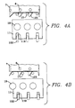
- Fig. 3A and Fig. 4A show the respective positions of the components and cam timing during initial start and rundown.
- the disengaging cam pin 17 progresses to the shutoff cam lobe 123 as reaction torque increases and begins to ride up the cam lobe which displaces the cam shaft 7 to the right and causes the drive dogs 122 to disengage from the clutch spindle 10, as shown in progression through Figs. 3B and 3C and Figs. 4B and 4C.
- Fig. 3D One feature of operation shown in Fig. 3D is the fact that as the shutoff valve 1 approaches throttle seat C the operating air or pneumatic fluid is throttled. This is accomplished by the fact that the shutoff valve 1 approaches the throttle seat C and also the chamber A is provided with a reducing taper 131 (as seen in Fig. 2) towards the throttle seat C. This results in restricted flow near shutoff and full flow of air during run down where operating speed is important to achieve.
Landscapes
- Engineering & Computer Science (AREA)
- General Engineering & Computer Science (AREA)
- Mechanical Engineering (AREA)
- Details Of Spanners, Wrenches, And Screw Drivers And Accessories (AREA)
- One-Way And Automatic Clutches, And Combinations Of Different Clutches (AREA)
- Hydraulic Clutches, Magnetic Clutches, Fluid Clutches, And Fluid Joints (AREA)
- Control Of Driving Devices And Active Controlling Of Vehicle (AREA)
- Mechanical Operated Clutches (AREA)
Applications Claiming Priority (3)
| Application Number | Priority Date | Filing Date | Title |
|---|---|---|---|
| US763373 | 1991-09-20 | ||
| US07/763,373 US5167309A (en) | 1991-09-20 | 1991-09-20 | Torque Control clutch |
| PCT/US1992/007640 WO1993006381A1 (en) | 1991-09-20 | 1992-09-09 | Torque control clutch |
Publications (2)
| Publication Number | Publication Date |
|---|---|
| EP0620900A1 EP0620900A1 (en) | 1994-10-26 |
| EP0620900B1 true EP0620900B1 (en) | 1996-03-27 |
Family
ID=25067663
Family Applications (1)
| Application Number | Title | Priority Date | Filing Date |
|---|---|---|---|
| EP92920471A Expired - Lifetime EP0620900B1 (en) | 1991-09-20 | 1992-09-09 | Torque control clutch |
Country Status (8)
| Country | Link |
|---|---|
| US (1) | US5167309A (OSRAM) |
| EP (1) | EP0620900B1 (OSRAM) |
| JP (1) | JPH07509555A (OSRAM) |
| CA (1) | CA2118922A1 (OSRAM) |
| DE (1) | DE69209524T2 (OSRAM) |
| ES (1) | ES2085036T3 (OSRAM) |
| TW (1) | TW197487B (OSRAM) |
| WO (1) | WO1993006381A1 (OSRAM) |
Families Citing this family (8)
| Publication number | Priority date | Publication date | Assignee | Title |
|---|---|---|---|---|
| FR2771040B1 (fr) * | 1997-11-17 | 2000-01-07 | Serac Group | Procede de commande d'une broche de vissage |
| US6045303A (en) * | 1998-12-02 | 2000-04-04 | Chung; Lee Hsin-Chih | Rotatable torque adjusting device of rotation tool |
| US6889778B2 (en) * | 2003-01-31 | 2005-05-10 | Ingersoll-Rand Company | Rotary tool |
| DE102008002594A1 (de) * | 2008-06-24 | 2009-12-31 | Robert Bosch Gmbh | Verfahren zum Betrieb einer Werkzeugmaschine mit Kupplungsvorrichtung |
| US20100024611A1 (en) * | 2008-07-29 | 2010-02-04 | Starick Michael M | Power driver and method of using the same |
| US9272400B2 (en) | 2012-12-12 | 2016-03-01 | Ingersoll-Rand Company | Torque-limited impact tool |
| US9737978B2 (en) | 2014-02-14 | 2017-08-22 | Ingersoll-Rand Company | Impact tools with torque-limited swinging weight impact mechanisms |
| CN109027030A (zh) * | 2018-08-10 | 2018-12-18 | 希美克(广州)实业有限公司 | 电机离合结构及具有该离合结构的窗帘、电动门窗 |
Family Cites Families (13)
| Publication number | Priority date | Publication date | Assignee | Title |
|---|---|---|---|---|
| US2881888A (en) * | 1954-01-26 | 1959-04-14 | Chicago Pneumatic Tool Co | Torque control clutch |
| US2780332A (en) * | 1955-01-03 | 1957-02-05 | Adele M Stevens | Automatically releasable torque transmitting apparatus |
| US3205992A (en) * | 1963-01-30 | 1965-09-14 | Ingersoll Rand Co | Automatic throttle torque responsive power tool |
| US3289715A (en) * | 1964-03-19 | 1966-12-06 | Aro Corp | Automatic shut-off tool |
| US3263785A (en) * | 1964-07-31 | 1966-08-02 | Ingersoll Rand Co | Torque releasing clutch mechanism and motor control |
| US3288258A (en) * | 1964-08-24 | 1966-11-29 | Ingersoll Rand Co | Torque releasing clutch mechanism |
| GB1213948A (en) * | 1969-06-12 | 1970-11-25 | Tapmatic Corp | Torque limiting clutch |
| GB1498968A (en) * | 1974-12-19 | 1978-01-25 | Bosch Gmbh Robert | Rotary power tool such as a power wrench |
| DE2505393C2 (de) * | 1975-02-08 | 1983-09-15 | Robert Bosch Gmbh, 7000 Stuttgart | Kraftwerkzeug, insbesondere Kraftschrauber |
| US4078618A (en) * | 1976-03-15 | 1978-03-14 | Gardner-Denver Company | Torque controller shutoff mechanism |
| US4265320A (en) * | 1977-05-16 | 1981-05-05 | Matsushita Electric Industrial Co., Ltd. | Electrically powered torque-controlled tool |
| US4223745A (en) * | 1978-09-15 | 1980-09-23 | Cooper Industries, Inc. | Torque responsive motor shutoff mechanism for fluid operated tool |
| JPS5834265B2 (ja) * | 1980-03-05 | 1983-07-26 | 瓜生製作株式会社 | エヤ−ドライバ−のクラツチ式トルク制御装置 |
-
1991
- 1991-09-20 US US07/763,373 patent/US5167309A/en not_active Expired - Lifetime
-
1992
- 1992-09-09 EP EP92920471A patent/EP0620900B1/en not_active Expired - Lifetime
- 1992-09-09 ES ES92920471T patent/ES2085036T3/es not_active Expired - Lifetime
- 1992-09-09 CA CA002118922A patent/CA2118922A1/en not_active Abandoned
- 1992-09-09 DE DE69209524T patent/DE69209524T2/de not_active Expired - Fee Related
- 1992-09-09 JP JP5506106A patent/JPH07509555A/ja active Pending
- 1992-09-09 WO PCT/US1992/007640 patent/WO1993006381A1/en not_active Ceased
- 1992-09-16 TW TW081107270A patent/TW197487B/zh active
Also Published As
| Publication number | Publication date |
|---|---|
| JPH07509555A (ja) | 1995-10-19 |
| DE69209524D1 (de) | 1996-05-02 |
| EP0620900A1 (en) | 1994-10-26 |
| CA2118922A1 (en) | 1993-04-01 |
| ES2085036T3 (es) | 1996-05-16 |
| DE69209524T2 (de) | 1996-09-05 |
| US5167309A (en) | 1992-12-01 |
| TW197487B (OSRAM) | 1993-01-01 |
| WO1993006381A1 (en) | 1993-04-01 |
Similar Documents
| Publication | Publication Date | Title |
|---|---|---|
| US5083619A (en) | Powered impact wrench | |
| CA1037796A (en) | Torque responsive motor shutoff for power tool | |
| US4078618A (en) | Torque controller shutoff mechanism | |
| US4782726A (en) | Lead screw driver | |
| US4631992A (en) | Screwdriver | |
| EP1501657B1 (en) | Air auto shutoff mechanism for a pneumatic torque-applying tool | |
| US3477521A (en) | Automatic power tool | |
| US4535850A (en) | Power-operated fastener tool | |
| US4576270A (en) | Torque control and fluid shutoff mechanism for a fluid operated tool | |
| US5201374A (en) | Screw joint tightening power tool | |
| EP0620900B1 (en) | Torque control clutch | |
| US3442362A (en) | Torque release and shut-off mechanism for pneumatic tools | |
| US4223745A (en) | Torque responsive motor shutoff mechanism for fluid operated tool | |
| US4875528A (en) | Torque control actuator | |
| CA1077313A (en) | Torque wrench air shut-off | |
| US3288258A (en) | Torque releasing clutch mechanism | |
| US3220526A (en) | One shot clutch | |
| GB2029746A (en) | Compressed air driven screwdriver | |
| US3543902A (en) | Torque transmission sytem | |
| US4592430A (en) | Fluid-pressure operated tools | |
| US5569118A (en) | Torque responsive release clutch mechanism | |
| US3237742A (en) | Torque releasing clutch mechanism with power cutoff | |
| USRE27550E (en) | Torque release and shut-off mechanism for pneumatic tools | |
| US5159987A (en) | Valve construction for automatic shut-off screwdrivers and the like | |
| GB1593032A (en) | Power tool with torque responsive shutoff mechanism |
Legal Events
| Date | Code | Title | Description |
|---|---|---|---|
| PUAI | Public reference made under article 153(3) epc to a published international application that has entered the european phase |
Free format text: ORIGINAL CODE: 0009012 |
|
| 17P | Request for examination filed |
Effective date: 19940419 |
|
| AK | Designated contracting states |
Kind code of ref document: A1 Designated state(s): CH DE ES FR GB IT LI SE |
|
| 17Q | First examination report despatched |
Effective date: 19941027 |
|
| GRAH | Despatch of communication of intention to grant a patent |
Free format text: ORIGINAL CODE: EPIDOS IGRA |
|
| GRAA | (expected) grant |
Free format text: ORIGINAL CODE: 0009210 |
|
| AK | Designated contracting states |
Kind code of ref document: B1 Designated state(s): CH DE ES FR GB IT LI SE |
|
| ITF | It: translation for a ep patent filed | ||
| REG | Reference to a national code |
Ref country code: CH Ref legal event code: NV Representative=s name: ISLER & PEDRAZZINI AG PATENTANWAELTE |
|
| REF | Corresponds to: |
Ref document number: 69209524 Country of ref document: DE Date of ref document: 19960502 |
|
| REG | Reference to a national code |
Ref country code: ES Ref legal event code: FG2A Ref document number: 2085036 Country of ref document: ES Kind code of ref document: T3 |
|
| ET | Fr: translation filed | ||
| PLBE | No opposition filed within time limit |
Free format text: ORIGINAL CODE: 0009261 |
|
| STAA | Information on the status of an ep patent application or granted ep patent |
Free format text: STATUS: NO OPPOSITION FILED WITHIN TIME LIMIT |
|
| 26N | No opposition filed | ||
| REG | Reference to a national code |
Ref country code: GB Ref legal event code: IF02 |
|
| PGFP | Annual fee paid to national office [announced via postgrant information from national office to epo] |
Ref country code: CH Payment date: 20020821 Year of fee payment: 11 |
|
| PGFP | Annual fee paid to national office [announced via postgrant information from national office to epo] |
Ref country code: ES Payment date: 20021009 Year of fee payment: 11 |
|
| PG25 | Lapsed in a contracting state [announced via postgrant information from national office to epo] |
Ref country code: ES Free format text: LAPSE BECAUSE OF NON-PAYMENT OF DUE FEES Effective date: 20030910 |
|
| PG25 | Lapsed in a contracting state [announced via postgrant information from national office to epo] |
Ref country code: LI Free format text: LAPSE BECAUSE OF NON-PAYMENT OF DUE FEES Effective date: 20030930 Ref country code: CH Free format text: LAPSE BECAUSE OF NON-PAYMENT OF DUE FEES Effective date: 20030930 |
|
| REG | Reference to a national code |
Ref country code: CH Ref legal event code: PL |
|
| REG | Reference to a national code |
Ref country code: ES Ref legal event code: FD2A Effective date: 20030910 |
|
| PGFP | Annual fee paid to national office [announced via postgrant information from national office to epo] |
Ref country code: GB Payment date: 20050831 Year of fee payment: 14 |
|
| PGFP | Annual fee paid to national office [announced via postgrant information from national office to epo] |
Ref country code: FR Payment date: 20050919 Year of fee payment: 14 |
|
| PGFP | Annual fee paid to national office [announced via postgrant information from national office to epo] |
Ref country code: SE Payment date: 20050921 Year of fee payment: 14 |
|
| PGFP | Annual fee paid to national office [announced via postgrant information from national office to epo] |
Ref country code: DE Payment date: 20051031 Year of fee payment: 14 |
|
| PG25 | Lapsed in a contracting state [announced via postgrant information from national office to epo] |
Ref country code: SE Free format text: LAPSE BECAUSE OF NON-PAYMENT OF DUE FEES Effective date: 20060910 |
|
| PGFP | Annual fee paid to national office [announced via postgrant information from national office to epo] |
Ref country code: IT Payment date: 20060930 Year of fee payment: 15 |
|
| PG25 | Lapsed in a contracting state [announced via postgrant information from national office to epo] |
Ref country code: DE Free format text: LAPSE BECAUSE OF NON-PAYMENT OF DUE FEES Effective date: 20070403 |
|
| EUG | Se: european patent has lapsed | ||
| GBPC | Gb: european patent ceased through non-payment of renewal fee |
Effective date: 20060909 |
|
| REG | Reference to a national code |
Ref country code: FR Ref legal event code: ST Effective date: 20070531 |
|
| PG25 | Lapsed in a contracting state [announced via postgrant information from national office to epo] |
Ref country code: GB Free format text: LAPSE BECAUSE OF NON-PAYMENT OF DUE FEES Effective date: 20060909 |
|
| PG25 | Lapsed in a contracting state [announced via postgrant information from national office to epo] |
Ref country code: FR Free format text: LAPSE BECAUSE OF NON-PAYMENT OF DUE FEES Effective date: 20061002 |
|
| PG25 | Lapsed in a contracting state [announced via postgrant information from national office to epo] |
Ref country code: IT Free format text: LAPSE BECAUSE OF NON-PAYMENT OF DUE FEES Effective date: 20070909 |