EP0620752B1 - Schwimmflosse mit mehreren auswechselbaren komponenten - Google Patents
Schwimmflosse mit mehreren auswechselbaren komponenten Download PDFInfo
- Publication number
- EP0620752B1 EP0620752B1 EP92922914A EP92922914A EP0620752B1 EP 0620752 B1 EP0620752 B1 EP 0620752B1 EP 92922914 A EP92922914 A EP 92922914A EP 92922914 A EP92922914 A EP 92922914A EP 0620752 B1 EP0620752 B1 EP 0620752B1
- Authority
- EP
- European Patent Office
- Prior art keywords
- sole plate
- swim fin
- foot
- channeling
- fin
- Prior art date
- Legal status (The legal status is an assumption and is not a legal conclusion. Google has not performed a legal analysis and makes no representation as to the accuracy of the status listed.)
- Expired - Lifetime
Links
- XLYOFNOQVPJJNP-UHFFFAOYSA-N water Substances O XLYOFNOQVPJJNP-UHFFFAOYSA-N 0.000 claims abstract description 71
- 230000005465 channeling Effects 0.000 claims abstract description 37
- 239000000463 material Substances 0.000 claims description 16
- 230000009182 swimming Effects 0.000 claims description 16
- 239000000758 substrate Substances 0.000 claims description 14
- 238000000034 method Methods 0.000 claims description 11
- 244000043261 Hevea brasiliensis Species 0.000 claims description 6
- 229920003052 natural elastomer Polymers 0.000 claims description 6
- 229920001194 natural rubber Polymers 0.000 claims description 6
- 229920003051 synthetic elastomer Polymers 0.000 claims description 6
- 239000005061 synthetic rubber Substances 0.000 claims description 6
- 230000009471 action Effects 0.000 claims description 5
- 229920000642 polymer Polymers 0.000 claims description 5
- 229920002635 polyurethane Polymers 0.000 claims description 5
- 239000004814 polyurethane Substances 0.000 claims description 5
- 239000006260 foam Substances 0.000 claims description 4
- 239000004033 plastic Substances 0.000 claims description 4
- 229920003023 plastic Polymers 0.000 claims description 4
- 229920005573 silicon-containing polymer Polymers 0.000 claims description 4
- 238000000465 moulding Methods 0.000 claims description 3
- 238000005553 drilling Methods 0.000 claims description 2
- 230000002093 peripheral effect Effects 0.000 claims 3
- 239000012858 resilient material Substances 0.000 claims 3
- 230000002708 enhancing effect Effects 0.000 claims 1
- 238000013461 design Methods 0.000 abstract description 16
- 210000002683 foot Anatomy 0.000 description 29
- 210000002414 leg Anatomy 0.000 description 6
- 230000004048 modification Effects 0.000 description 5
- 238000012986 modification Methods 0.000 description 5
- 210000003205 muscle Anatomy 0.000 description 5
- 239000007787 solid Substances 0.000 description 5
- 241000282414 Homo sapiens Species 0.000 description 4
- 230000008901 benefit Effects 0.000 description 4
- 230000000694 effects Effects 0.000 description 4
- 230000001141 propulsive effect Effects 0.000 description 4
- OKTJSMMVPCPJKN-UHFFFAOYSA-N Carbon Chemical compound [C] OKTJSMMVPCPJKN-UHFFFAOYSA-N 0.000 description 3
- 229910002804 graphite Inorganic materials 0.000 description 3
- 239000010439 graphite Substances 0.000 description 3
- 241001465754 Metazoa Species 0.000 description 2
- PXHVJJICTQNCMI-UHFFFAOYSA-N Nickel Chemical compound [Ni] PXHVJJICTQNCMI-UHFFFAOYSA-N 0.000 description 2
- 210000003484 anatomy Anatomy 0.000 description 2
- 238000005260 corrosion Methods 0.000 description 2
- 230000007797 corrosion Effects 0.000 description 2
- 210000001624 hip Anatomy 0.000 description 2
- 239000000203 mixture Substances 0.000 description 2
- 229920003225 polyurethane elastomer Polymers 0.000 description 2
- 239000012779 reinforcing material Substances 0.000 description 2
- 229920002379 silicone rubber Polymers 0.000 description 2
- 239000003381 stabilizer Substances 0.000 description 2
- 241000251468 Actinopterygii Species 0.000 description 1
- VYZAMTAEIAYCRO-UHFFFAOYSA-N Chromium Chemical compound [Cr] VYZAMTAEIAYCRO-UHFFFAOYSA-N 0.000 description 1
- 241000935974 Paralichthys dentatus Species 0.000 description 1
- 229920002323 Silicone foam Polymers 0.000 description 1
- 229910000831 Steel Inorganic materials 0.000 description 1
- 230000008859 change Effects 0.000 description 1
- 229910052804 chromium Inorganic materials 0.000 description 1
- 239000011651 chromium Substances 0.000 description 1
- 239000002131 composite material Substances 0.000 description 1
- 230000007423 decrease Effects 0.000 description 1
- 230000003247 decreasing effect Effects 0.000 description 1
- 238000011161 development Methods 0.000 description 1
- 230000009189 diving Effects 0.000 description 1
- 229920001971 elastomer Polymers 0.000 description 1
- 239000000945 filler Substances 0.000 description 1
- 239000004619 high density foam Substances 0.000 description 1
- 210000004394 hip joint Anatomy 0.000 description 1
- 230000006872 improvement Effects 0.000 description 1
- 230000007935 neutral effect Effects 0.000 description 1
- 229910052759 nickel Inorganic materials 0.000 description 1
- 229920001296 polysiloxane Polymers 0.000 description 1
- 238000002360 preparation method Methods 0.000 description 1
- 230000008569 process Effects 0.000 description 1
- 230000004044 response Effects 0.000 description 1
- 230000000717 retained effect Effects 0.000 description 1
- 239000005060 rubber Substances 0.000 description 1
- 238000010561 standard procedure Methods 0.000 description 1
- 239000010959 steel Substances 0.000 description 1
- 238000005728 strengthening Methods 0.000 description 1
- 238000002560 therapeutic procedure Methods 0.000 description 1
- 210000003371 toe Anatomy 0.000 description 1
- 238000012549 training Methods 0.000 description 1
- 210000000689 upper leg Anatomy 0.000 description 1
Images


Classifications
-
- A—HUMAN NECESSITIES
- A63—SPORTS; GAMES; AMUSEMENTS
- A63B—APPARATUS FOR PHYSICAL TRAINING, GYMNASTICS, SWIMMING, CLIMBING, OR FENCING; BALL GAMES; TRAINING EQUIPMENT
- A63B31/00—Swimming aids
- A63B31/08—Swim fins, flippers or other swimming aids held by, or attachable to, the hands, arms, feet or legs
- A63B31/10—Swim fins, flippers or other swimming aids held by, or attachable to, the hands, arms, feet or legs held by, or attachable to, the hands or feet
- A63B31/11—Swim fins, flippers or other swimming aids held by, or attachable to, the hands, arms, feet or legs held by, or attachable to, the hands or feet attachable only to the feet
-
- A—HUMAN NECESSITIES
- A63—SPORTS; GAMES; AMUSEMENTS
- A63B—APPARATUS FOR PHYSICAL TRAINING, GYMNASTICS, SWIMMING, CLIMBING, OR FENCING; BALL GAMES; TRAINING EQUIPMENT
- A63B71/00—Games or sports accessories not covered in groups A63B1/00 - A63B69/00
- A63B71/0009—Games or sports accessories not covered in groups A63B1/00 - A63B69/00 for handicapped persons
-
- A—HUMAN NECESSITIES
- A63—SPORTS; GAMES; AMUSEMENTS
- A63B—APPARATUS FOR PHYSICAL TRAINING, GYMNASTICS, SWIMMING, CLIMBING, OR FENCING; BALL GAMES; TRAINING EQUIPMENT
- A63B2208/00—Characteristics or parameters related to the user or player
- A63B2208/12—Characteristics or parameters related to the user or player specially adapted for children
-
- A—HUMAN NECESSITIES
- A63—SPORTS; GAMES; AMUSEMENTS
- A63B—APPARATUS FOR PHYSICAL TRAINING, GYMNASTICS, SWIMMING, CLIMBING, OR FENCING; BALL GAMES; TRAINING EQUIPMENT
- A63B2225/00—Miscellaneous features of sport apparatus, devices or equipment
- A63B2225/09—Adjustable dimensions
Definitions
- This invention relates to the field of swim fins. More particularly this invention relates to the modification of swim fins which can vary the effect of the swimmers foot and leg stroke on the water through which the swimmer swims, for various end results.
- fins In an effort to improve man's swimming abilities, a number of inventors have designed and produced fins adapted to be worn on the feet while swimming. Generally, fins have a foot retaining portion and a relatively large blade extending in a forward direction with respect to the body. Most are made from elastomeric materials such as rubber, polyurethane or silicones. Newer fins are made from combinations of these materials and may be reinforced with strengthening fillers such as graphite.
- U.S. Patents 4,929,206 and 4,857,024 describe fins with upwardly curving blade tips. This design results in an opening of the blade as the swimmer executes a power or downstroke and a snapping action of the tips as the swimmer executes an upstroke. The opening action on the downstroke increases propelling force while the snapping action on the upstroke decreases the amount of energy needed by the swimmer to reposition his leg for another downstroke.
- fins having ribs U.S. Patent No. 4,820,218), flexible canals (U.S. Patent No. 4,738,645), baffles (U.S. Patent No. 4,627,820), stabilizers (U.S. Patent No. 3,913,158), leading edges (U.S. Patent No. 3,810,269), upcurving wingtips (U.S. Patents Nos. 4,929,206 and 4,857,024), and hydrofoils (U.S. Patent No. 4,944,703).
- Battens provide either more or less resistance, however the surface area of the fin and thus the effective propulsion is not changed. Ribs are fixed and cannot be varied according to the needs of the swimmer and water conditions.
- Baffles and vents combine forces exerted by the swimmer with water pressure forces moving through the blade. Such openings will not allow sufficient flow of water thus creating a backpressure which increases resistance. Stabilizers and leading edges are fixed and stationary, and will not respond to changes in water pressure or forces exerted by the swimmer.
- the swim fin in its simplest form relates to a truncated swim fin or sole plate adapted to be worn on the foot of a swimmer for the purpose of varying the effect of the swimmer's leg strokes.
- the swim fin can be made more resistive or more propulsive or both, depending on the swimmer's needs.
- the swim fin has a sole plate having a rear portion of roughly rectangular shape and a front portion of roughly trapezoid shape.
- the sole plate is fairly thin, of fairly constant thickness and is generally flat. Thicknesses of about 1/4 inch work quite well.
- the sole plate should be larger than the largest foot that can be expected in the general population.
- the sole plate has a plurality of mounting holes or slots, which will be clear of the foot after the sole plate is securely fastened to the foot.
- an elongated swim fin is the basic modular component.
- a means of securing the sole plate or fin to the sole of the swimmer's foot is provided.
- integral with the rear portion of the sole plate or fin is a pair of arcuate shaped flaps which are comfortable to the instep of the foot of a swimmer. These flaps extend upwards and forwards from the rear portion of the fin or sole plate and form a tunnel or channel of variable diameter into which the swimmer's foot may be inserted.
- To complete the securing means are heel straps, attached to the arcuate shaped flaps, and another set of straps attached over the top of the arcuate shaped flaps which can adjust the diameter of the tunnel or channel formed between the flaps.
- the effective lengths of these pairs of straps can be adjusted, for snug fit around a foot of any size, by any conventional means such as buckles or hook and pile fasteners.
- Each vane has a mounting hole through which it can be fastened to one of the holes or slots in the sole plate or fin.
- the vanes may be of many, selected and different designs, including straight or curved in one or two dimensions depending upon the end results desired.
- the mounting holes may be located at one end or centrally of the sole plate or fin.
- Means for attaching the vanes to the sole plate or fin are also provided. This may be accomplished in many different but standard ways. It may be done, for example, with nuts and bolts or with threaded inserts and bolts. The inserts may be molded into the holes in the vanes. Bolts may be suitably modified for ease of turning with the fingers. The bearing surfaces of the bolts or the nuts or both may be knurled so that, when fastened down, the vanes will not easily rotate or change position unless so desired by the user. As another assembly aid, the holes or slots in the fin or sole plate may be designed to retain the nuts and prevent them from turning, for relatively immobile association with the fin or sole plate.
- the sole plate, or fin and flaps and vanes as is typical of swim fins in general are made of a rigid or flexible material such as natural rubber, synthetic rubber, silicone polymer, polyurethane polymer, or foam compositions, or composites of these materials.
- the sole plate or fin and flaps are formed as a one piece integral molding. It is possible to attach vanes of different designs to various, selected locations on the upper alone or upper and lower surfaces of the sole plate and likewise for the basic, modular swim fin.
- one flap joining the two sides of the sole plate or swim fin may be provided instead of two.
- This single flap may be shaped like a tunnel or channel of decreasing diameter into which the swimmer's foot may be inserted.
- an essentially hemispherical pod may be attached to the center of the lower surface of the sole plate or swim fin.
- Such a pod diverts water from the central portion of the lower surface of the sole plate or swim fin, a known dead spot, in order to permit greater swimming speed.
- a fin-like extension of essentially truncated triangular shape may be attached to the fore portion of the sole plate. This makes the shape of the sole plate similar to a conventional fin, providing greater surface area and permits greater swimming speed.
- the basic derived attributes of this invention may also be found by providing modular components in kit form to swimmers who already have swim fins and do not desire to purchase others.
- the kit contain sets of vanes, fasteners for the vanes and a template for alignment purposes for drilling holes, for example, in existing fins. The owner simply drills holes in his existing fins, as indicated in the template and attaches vanes or other modular components in order to achieve the desired effect that the swimmer wants.
- vane components can be attached to any point on the upper and lower surfaces of the specially provided sole plate or to the blade of any existing fin in order to make the fin more resistive or more propulsive as desired. This allows the swimmer to target certain muscles for resistance and also to channel water past the fin or sole plate in order to provide more propulsion. For example, should a swimmer have a hip joint replacement, that hip requires more therapy than the other hip and selective placement of modular elements, to increase water resistance, provides this capability.
- Figure 1 is a top perspective view of one embodiment of the present invention.
- Figures 1A and 1B represent alternate ways of fastening the invention to the foot.
- Figure 1A is similar to the embodiment depicted in Figure 1, but illustrating an alternate fastening means.
- Figure 1B is similar to the embodiment depicted in Figures 1 and 1B, but illustrating still another alternate, fastening means.
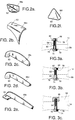
- FIGS 2a-2f inclusive illustrate perspective views of several modular components of water channeling vanes of the invention.
- FIGS 3a-3c illustrate fragmented, cross-sectional views of various means of attaching the vanes to the sole plate or swim fin of the invention.
- Figures 4a-4c inclusive show partial views of several varieties of the water channeling vanes applied to the sole plate, for example, of the present invention.
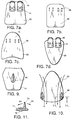
- FIGS 5a and 5b show partial views of the addition of several varieties of fin extension modules to the sole plate, for example, of the present invention.
- FIGS 6a-6d inclusive illustrate several alternate shapes for fin extension modules.
- Figures 7a-7d inclusive illustrate the manner in which the enlarged fin extensions or modules of various shapes may be secured to a pair of sole plates to make a uni-fin or the like.
- FIGS 8a-8g inclusive illustrate partial views of addition of several varieties of fin modules to other types of conventional swim fins.
- Figure 9 is a fragmented view of to the sole plate of the present invention to which has been affixed a speed pod module.
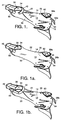
- Figure 10 illustrates water flow over a fin of the present invention as it moves through the water.
- Figure 11 is a cross section taken along the line 11-11 of Figure 10 and illustrates how the water channeling vanes flex as a fin of the present invention moves through the water.
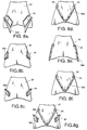
- Figure 12a-12f inclusive are schematic frontal views of a fin of the present invention, showing flexing of the various modules and water flow during the up and down strokes of a fin of the invention.
- FIG. 1 shows a top, perspective view of the swim fins of the present invention.
- the fin 10 comprises a main portion sole plate 14 forming the basic component to which various modules, as will become clear, may be secured.
- the sole plate 14 has a front portion 18, a rear portion 22, and an upper surface 26 and a lower surface 30.
- the sole plate 14 is essentially flat, planar and about 1/4 inch thick.
- the front portion 18 has a roughly trapezoidal shape, while the rear portion 22 has a roughly rectangular shape.
- the whole sole plate 14 is larger than a swimmer's foot, not shown. It is understood that only one swim fin will be described and that swimmers utilize two such fins when swimming or exercising using the invention.
- Flaps 34 integral with top surface 26 of rear portion 22 are a pair of extending, arcuate-shaped flaps 34. Flaps 34 extend upward and forward from the rear portion 22 and may additionally curve inward slightly with reference to the center line of sole plate 14. Flaps 34 form a tunnel or channel 38 into which the swimmer's foot is received. The flaps 34 provide support to the sides of the swimmer's foot and forms the means whereby the sole plate 14 does not significantly twist during use.
- the top straps 42 are attached to the flaps 34 so that they will pass over the top or instep of the swimmer's foot.
- the top straps 42 adjust the size or diameter of the tunnel or channel 38 so that the swimmer's foot will be firmly held within the formed channel and between the arcuate flaps 34.
- the heel straps 46 are attached to the lower portion of flaps 34 so that they will pass around the heel of the swimmer's foot. The purpose of the heel straps 46 is to assure that the swimmer's foot is retained within the confines of the tunnel or channel 38 so that the foot will not slip out of the tunnel or channel 38 to the rear.
- Both pairs of straps 42 and 46 may be secured and adjusted with buckles 50 or hook and pile fasteners such as Velcro TM.
- the purpose of the flaps 34, straps 42, 46 and buckles 50 or hook and pile fasteners, is to securely associate the sole plate 14 with the sole of the swimmer's foot. It is obvious from the prior art, and the Inventor's own prior U.S. Patents, Nos. 4,857,024 and 4,929,206 that other association designs will work equally well.
- one flap 34, thereby forming a pocket 39 could be provided fastened to the rear 22 of the sole plate, thus, forming a tunnel, channel or pocket 39 of reducing diameter, into which the foot is inserted. This modification is illustrated in Figure 1a. In this case the top straps 42 would be unnecessary.
- the sole plate 14 and flaps 34 are integral or molded in one piece.
- the sole plate 14 and flaps 34 ideally are made from a flexible or rigid material.
- Commonly used fin materials such as natural rubber, synthetic rubber, polyurethane elastomers, silicone elastomers, or combinations of these materials may be used.
- these materials may be filled with a reinforcing material such as graphite or the like.
- Sole plate 10 is provided with a number of spaced and aligned holes or slots 54. It is through these holes or slots 54 that the modular elements or water channeling vanes 58 are attached.
- the water channeling vanes 58 may have a variety of different shapes: right angle vanes 58a and winglets 58b are illustrated in Figure 1.
- Each vane 58 illustrated in this instance has a single mounting hole 62, which may be located anywhere on the vane 58.
- Vanes 58a and 58b are shown attached, in a specific position and with a specific orientation, to the top surface 26 and the bottom surface 30 of sole plate 14. It should be recognized, however, that sole plate 14 may be used very effectively without any vanes 58 attached. Further, the vanes 58a, 58b may be attached singly rather than in pairs, at other locations 54 on sole plate 14, on the top surface 26 or the bottom surface 30 of sole plate 14 and with different orientations.
- the devices of this invention since they have a variety of interchangeable modular components, may be assembled into many different configurations according to the swimmer's desires.
- FIGs 2a-f illustrate a variety of differently configured vanes 58.
- the right angle vane 58a and winglet 58b vanes have already been mentioned.
- three configurations of whiskers 58c, 58d, 58e and a solid wing 58f are also illustrated.
- the solid wing 58f exerts a pressurization/depressurization action similar to that of an aircraft wing.
- Each of the vanes 58 illustrated has a single mounting hole 62. The location of the mounting hole 62 is optional but is dictated by the end function of the vane 58. In the right angle vane 58a and the solid wing 58f, the hole 62 is located centrally.
- vanes 58b, c, d, e the hole 62 is located towards one end. While preferred vanes 58 have been illustrated, it should be recognized that other vane designs 58 are possible with varying numbers of holes 62 and different hole locations.
- the winglet vanes 58c-58e will slightly bend or flex when in use with sole plate or fin, thereby producing various desired end results for the swimmer.
- the vanes 58 may also be made from standard rigid and flexible fin materials such as natural rubber, synthetic rubber, polyurethane elastomers, silicone elastomers, or foam compositions or combinations of these materials. Furthermore, these materials could be filled with a reinforcing material such as graphite. The purpose of these vanes 58 is to channel water in specific directions as it passes over the fin 10, for example.
- the vanes 58 can be attached to the fins by a variety of standard methods.
- Figures 3a-c show cross-sections of some typical methods of attachment.
- Figure 3a shows attachment with a nut 66 and bolt 70.
- the nut 66 and bolt 70 should preferably be manufactured from corrosion resistant, nickel plated or chromium plated steel.
- plastic bolts 70 and nuts 66 may be utilized.
- the bolt 70 should be provided with a large head 74 for ease of assembly by the fingers.
- the bearing faces 78 of the nut 66 or the bolt 70 or both should be knurled so that fastener clamping force will not be lost during use of the fin 10.
- FIG. 3b illustrates sockets 82 in the sole plate 14.
- fastening may be accomplished with threaded inserts 86 and bolts 70.
- the inserts 86 are molded into the vanes 58 so as to be accessible from the outside.
- the bolts 70 are fabricated of corrosion resistant materials and provided with large heads 74 and serrated bearing surfaces 78. It should be obvious that other methods of attaching the vanes to the sole plates or fins may be devised, using standard fastening techniques.
- a single vane 58, a pair of vanes 58 or multiple pairs of vanes 58 may be attached to sole plate 14 or to conventional fins as will be described. Additionally, vanes may be attached to the top surface 26 or the bottom surface 30 of the sole plate 14 at various locations 54 and with various orientations.
- Figures 4a-c illustrate the sole plate 14 with a variety of vanes 58 attached to it in different orientations. Although only a few are illustrated in Figures 4a-c, it should be obvious that many different combinations are possible.
- Each vane 58 has a different effect on the swimmer's capabilities.
- the combination shown in Figure 4a will tend to reduce swimming speed. This is useful if the swimmer must exercise in a small pool or he desires to preferentially exercise the muscles in his thigh.
- the combination shown in figure 4b focuses the water into the working area of the fin resulting in greater propulsion.
- the orientation shown in Figure 4c results in more stability for the swimmer. It can be seen that it is possible to attach vanes 58 of different designs to many locations 54 on the upper surface 26 and lower surface 30 of sole plate 14 on to a conventional fin. This enables the swimmer to swim faster, exercise specific muscles, compensate for physical disparities between the two legs, or swim more slowly, as desired.
- fin extension 90 may be provided which may be fastened to the sole plate 14 with fasteners 94 as illustrated in Figures 5a and b.
- FIG 5a an extension 90 is shown joined to the end of sole plate 14 by what is essentially an overlap joint. The two pieces are joined by spaced fasteners 94.
- Figure 5b illustrates an alternate manner of fastening an extension 90. In this version the extension 90 is longer and extends underneath sole plate 14.
- the extension 90 is provided with a series of slots 88 so that its position in relation to the sole plate 14 may be infinitely varied.
- the fin 14 will have all the capabilities of a regular swim fin, i.e. it can develop enough power for all uses, and in addition various vanes 58 may be fastened to it, as previously described.
- this invention fulfills multiple purposes.
- the extension 90 may have a variety of different shapes. Some examples are shown in Figures 6a-d. The extension 90 can even be made so that a pair of sole plates 14 may be fastened as illustrated in Figures 7a-d, to thereby produce a mono-fin, designed to receive both feet of the swimmer. Referring to Figures 8a-g inclusive it will be seen that most fins sold today have a foot retaining portion and a large, triangular shaped blade 92 extending forwards. This invention can also be provided to swimmers who already have such fins and do not wish to purchase another set. In this case a kit is provided to the swimmer, consisting of a template, not shown, an assortment of vanes 58 and means 94 for fastening the vanes 58.
- FIG. 8a-g illustrate some of the variety of possibilities that may result from use of the modular elements making up the kit. Swimmers who already have fins would in this way be able to realize some of the advantages of this invention without resort to purchasing the basic sole plate, substrate or fin.
- a speed pod 98 is also provided as part of this invention.
- the speed pod 98 is shaped like a streamlined hemisphere: in other words it has a tear drop shape.
- the speed pod may be any convenient size and may be made from high density foam, or solid plastic. It can even be filled with a heavy material such as lead.
- the speed pod 98 can be attached to the top surface 26 or underside surface 30 of the sole plate 14 or an existing fin using, preferably, bolt 70 and threaded insert 86 as previously described.
- Use of the speed pod 98 by diverting water from the dead spot in the middle of the sole plate 14 or any fin, will enable the swimmer to swim faster. If the pod is made of foam, it will keep the swimmer's feet high in the water. If the pod is made from a dense solid plastic or is filled with lead, it will make the swimmer's feet sink, thus making his legs work harder for additional exercise.
- FIG 10 illustrates water flow over one embodiment of swim fin 10 of the invention as it travels through the water.
- Water flow is shown by the arrows 60.
- Water flow in direction of the arrows 60 will differ as different vanes 58 are attached to sole plate 14 or a conventional fin.
- Water flow will also differ as different vanes 58 are attached in different positions on the upper surface 26 and lower surface 30 and as each is turned to a different angle.
- the structure of some modular vanes 58, away from the attachment point 62 allows freedom of movement in response to forces produced by water flow.
- the modular vanes 58 flex from their normal fixed position relative to blade 92 or sole plate 14 allowing the water to pass to the rear of the blade 92 or sole plate 14. This increases the propulsive forces in the vertical direction thus increasing fin efficiency.
- Figure 11 illustrates how the vanes 58 flex as the swim fin 10 moves through the water.
- the vane 58 flexes inward and outward as shown by the arrows 64.
- FIG. 12a-f it will be seen how the entire swim fin 10 flexes and how water flows as the swimmer executes his up and down strokes.
- the position shown as 0 is essentially neutral and neither the sole plate 14 nor the vanes 58 are flexed from their normal positions. In this position the swimmer's toes 100 are clearly visible.
- the sole plate 14 flexes upwards, the vanes 58 flex inward and water flows inward as shown by the arrows 60.
- the sole plate 14 flexes downwards, the vanes 58 flex outward and water flows outward as shown by the arrows 60.
- the advantages of the water channeling vanes 58 described above are that they can be placed at any desired location depending on the surface configuration of the conventional fin or the sole plate 14. They can be placed at the side so as to create a leading edge or at the trailing edge so as to continue water flow beyond the surface area of the fin blade 92.
- All swim fins create turbulence or vortices as the swimmer swims through the water.
- the locations of these vortices or areas of turbulence will vary according to the design of the blade.
- the water channeling vanes 58 can also be placed at any point along the conventional swim fin blade 92 or sole plate 14 in order to limit these vortices or areas or turbulence as well as eddies and dead spaces.
- a uniform pressure wave moving past a fin will propel a swimmer through the water much better than a turbulent pressure wave. In this way the water channeling vanes 58 increase the fin's efficiency.
- the new and improved fin 10 of this invention responds to the needs of the swimmer, whether to provide more resistance or to provide better, less turbulent water flow past the fin. Either goal is achieved by judicious placement of the various water channeling vanes 58 on the fin or sole plate 14. No prior art fin has this type of design flexibility.
Landscapes
- Health & Medical Sciences (AREA)
- General Health & Medical Sciences (AREA)
- Physical Education & Sports Medicine (AREA)
- Toys (AREA)
- Footwear And Its Accessory, Manufacturing Method And Apparatuses (AREA)
Claims (28)
- Schwimmflosse (10), die angepasst ist, um an einem Fuss eines Schwimmers getragen zu werden, die umfasst:
eine Trägereinrichtung (14, 92), die mit einer kanalisierenden Einrichtung versehen ist und die grösser ist als der Fuss;
eine Befestigungseinrichtung (34, 41, 42, 46) um die Trägereinrichtung (14, 92) am Fuss zu befestigen, so dass die Trägereinrichtung (14, 92) eng anliegend an der Fussohle gehalten wird;
dadurch gekennzeichnet, dass die kanalisierende Einrichtung aus einer einstellbaren kanalisierenden Einrichtung (58a-e) besteht, um das Wasser einstellbar und steuerbar zu kanalisieren, wobei die kanalisierende Einrichtung (58a-e) um eine Achse senkrecht zur Längs- und Querachse der Flosse (10) wahlweise in eine bestimmte Orientierung gedreht werden kann und im wesentlichen von der Schwimmflosse (10) weg und in das Wasser hinein um die Schwimmflosse herum vorragt, um die Strömung des Wassers um die Schwimmflosse herum zu kanalisieren; und dadurch, dass
eine Befestigungseinrichtung (66, 70, 86, 94) bereit gestellt wird, um die kanalisierende Einrichtung (58a-e) an der Trägereinrichtung (14, 92) in einer fixen Position in gehörigem Abstand vom Fuss zu befestigen. - Schwimmflosse nach Anspruch 1, dadurch gekennzeichnet, dass die Trägereinrichtung (14, 92) und die Befestigungseinrichtung (34) als ein Stück in integraler Form aus einem elastischen Material gebildet sind.
- Schwimmflosse nach Anspruch 2, dadurch gekennzeichnet, dass das elastische Material aus der Gruppe ausgewählt wird, die aus natürlichem Gummi, synthetischem Gummi, einem Silikonpolymer und einem Polyurethanpolymer besteht.
- Schwimmflosse nach Anspruch 1, dadurch gekennzeichnet, dass die kanalisierende Einrichtung (58a-e) aus einem Material hergestellt ist, das aus der Gruppe ausgewählt wird, die aus natürlichem Gummi, synthetischem Gummi, einem Silikonpolymer und einem Polyurethanpolymer besteht.
- Schwimmflosse nach Anspruch 1, dadurch gekennzeichnet, dass sie zusätzlich eine Hülseneinrichtung (98) umfasst, die loslösbar an der Trägereinrichtung (14, 92) befestigt ist, um Wasser von der Trägereinrichtung (14, 92) abzulenken, damit eine grössere Schwimmgeschwindigkeit ermöglicht wird.
- Schwimmflosse nach Anspruch 5, dadurch gekennzeichnet, dass die Hülseneinrichtung (98) aus einem Material hergestellt ist, das aus der Gruppe ausgewählt wird, die aus natürlichem Gummi, synthetischem Gummi, einem Silikonpolymer, einem Polyurethanpolymer, einem Polymerschaumstoff und einem mit Blei gefüllten Plastik besteht.
- Schwimmflosse nach Anspruch 1, dadurch gekennzeichnet, dass sie zusätzlich eine Verlängerungseinrichtung (90) von im wesentlichen gekürzter, dreieckiger Form umfasst, die loslösbar an der Trägereinrichtung (14) befestigt ist, um eine grössere Oberfläche für die Schwimmflosse (10) und eine grössere Schwimmkraft zu liefern.
- Schwimmflosse nach Anspruch 1, dadurch gekennzeichnet, dass die Befestigungseinrichtung (66, 70, 86, 94) aus der Kombination von einer Mutter und einer Schraube (66, 70) besteht, bei welcher die Kombination aus Mutter und Schraube (66, 70) angepasst ist, um leicht von Hand gedreht zu werden.
- Schwimmflosse nach Anspruch 8, dadurch gekennzeichnet, dass die Mutter (66) eine gerändelte tragende Seite hat.
- Schwimmflosse nach Anspruch 8, dadurch gekennzeichnet, dass die Schraube (70) eine gerändelte tragende Seite hat.
- Schwimmflosse nach Anspruch 8, dadurch gekennzeichnet, dass die Mutter (66) und die Schraube (70) eine gerändelte tragende Seiten haben.
- Schwimmflosse nach Anspruch 8, dadurch gekennzeichnet, dass sie zusätzlich eine Einrichtung (82) umfasst, die in der Trägereinrichtung (14) eingebaut ist, um die Mutter (66) am Drehen zu hindern.
- Schwimmflosse nach Anspruch 1, dadurch gekennzeichnet, dass die Befestigungseinrichtung (66, 70, 86, 94) aus der Kombination von einem Gewindeeinsatz und einer Schraube (70, 86) besteht, wobei die Schraube (70) angepasst ist, um leicht von Hand gedreht zu werden, und der Einsatz (86) in der kanalisierenden Einrichtung (58a-e) geformt ist.
- Schwimmflosse nach Anspruch 13, dadurch gekennzeichnet, dass die Schraube (70) eine gerändelte tragende Seite hat.
- Schwimmflosse nach Anspruch 1, dadurch gekennzeichnet, dass die Befestigungseinrichtung (34, 41, 42, 46) einstellbar ist, um an verschiedene Grössen des Fusses angepasst zu werden.
- Schwimmflosse nach irgend einem der Ansprüche 1 bis 15, dadurch gekennzeichnet, dass
die Trägereinrichtung (14, 92) eine Sohlenplatte (14) umfasst, die eine vordere Partie (18), eine hintere Partie (22), eine Oberseite (26) und eine Unterseite (30) hat, wobei die Unterseite (30) eine mittlere Partie und eine Randpartie definiert,
wobei die Sohlenplatte (14) eine vielzahl von Montageöffnungen (54) hat, die in gehörigem Abstand vom Fuss sein werden, nachdem die Sohlenplatte (14) am Fuss befestigt ist,
wobei die kanalisierende Einrichtung (58a-e) eine Leitschaufel (58a-e) zum Kanalisieren des Wassers umfasst, die ein Montageloch (62) hat, und
die Leitschaufel (58a-e) zum Kanalisieren des Wassers, durch das Montageloch (62) der Leitschaufel (58a-e) zum Kanalisieren des Wassers und mindestens eine der Montageöffnungen (54) der Sohlenplatte (14) in einer fixen Position an der Sohlenplatte (14) befestigt ist. - Schwimmflosse nach Anspruch 16, dadurch gekennzeichnet, dass sie zusätzlich eine im wesentlichen halbkugelförmige Hülse (98) umfasst, die loslösbar an der Unterseite (30) der Sohlenplatte (14) befestigt ist, wobei die im wesentlichen halbkugelförmige Hülse (98) Wasser von der mittleren Partie der Unterseite (30) der Sohlenplatte (14) ablenkt, um eine grössere Schwimmgeschwindigkeit zu ermöglichen.
- Schwimmflosse nach Anspruch 16, dadurch gekennzeichnet, dass sie zusätzlich eine Flossenverlängerung (90) von im wesentlichen gekürzter, dreieckiger Form umfasst, die loslösbar an der vorderen Partie (18) der Sohlenplatte (14) befestigt ist, um eine grössere Oberfläche für die Schwimmflosse (10) und eine grössere Schwimmkraft zu liefern.
- Schwimmflosse Anspruch 1, dadurch gekennzeichnet, dass
die Trägereinrichtung (14, 92) eine Sohlenplatte (14) umfasst, die eine vordere Partie (18), eine hintere Partie (22), eine Oberseite (26) und eine Unterseite (30) hat, wobei die Unterseite (30) eine mittlere Partie und eine Randpartie definiert,
eine erste bogenförmige Klappe (34), die in die hintere Partie (22) der Sohlenplatte (14) integriert ist und sich von ihr nach oben und nach vorne erstreckt, und die einen Tunnel (38) mit variablem Durchmesser bildet, in welchen der Fuss eingeschoben werden kann,
einen Fersenriemen (41) von einer bestimmten Länge, der an der bogenförmigen Klappe (34) befestigt ist und welcher um die Ferse des Fusses herum passen wird, nachdem der Fuss in den durch die erste bogenförmige Klappe (34) gebildeten Tunnel (38) hinein geschoben wurde,
eine Einrichtung (50) zum Einstellen der Länge des Fersenriemens (41), so dass die Oberseite (26) der Sohlenplatte (14) eng anliegend an der Fussohle gehalten wird, nachdem der Fuss in den Tunnel (38) hinein geschoben wurde,
wobei die Sohlenplatte (14) eine vielzahl von Montageöffnungen (54) hat, die in gehörigem Abstand vom Fuss sind, nachdem der Fuss in den Tunnel (38) hinein geschoben wurde,
wobei die kanalisierende Einrichtung (58a-e) eine Leitschaufel (58a-e) zum Kanalisieren des Wassers umfasst, die ein Montageloch (62) hat, und
die Leitschaufel (58a-e) zum Kanalisieren des Wassers durch das Montageloch (62) der Leitschaufel (58a-e) zum Kanalisieren des Wassers und mindestens eine der Montageöffnungen (54) der Sohlenplatte (14) hindurch in einer fixen Position an der Sohlenplatte (14) befestigt ist. - Schwimmflosse nach Anspruch 19, dadurch gekennzeichnet, dass die Sohlenplatte (14) und die bogenförmige Platte (34) als ein Stück in integraler Form aus einem elastischen Material gebildet sind.
- Schwimmflosse nach Anspruch 19, dadurch gekennzeichnet, dass sie zusätzlich umfasst:
eine zweite bogenförmige Klappe (34), die in die hintere Partie (22) der Sohlenplatte (14) integriert ist und sich von ihr nach oben und nach vorne erstreckt und die mit der ersten bogenförmigen Klappe (34) einen Tunnel (38) mit variablem Durchmesser bildet, in welchen der Fuss eingeschoben werden kann, und
eine Einrichtung (42) zum Einstellen des Durchmessers des durch die erste und die zweite bogenförmige Klappe (34) gebildeten Tunnels (38). - Schwimmflosse nach Anspruch 1, dadurch gekennzeichnet, dass die Trägereinrichtung (14) eine den Fuss aufnehmende Partie (22) und eine sich erstreckende Arbeitspartie (18) hat, wobei die Arbeitspartie (18) eine Oberseite und eine Unterseite (26, 30) hat, wobei auf mindestens einer der Ober- und Unterseiten (26, 30) ein Modul (58a-e, 92) montiert ist, das die kanalisierende Einrichtung (58a-e) umfasst, die konfiguriert ist, um die Wirkung des Wassers auf die mindestens eine der Ober- und Unterseiten (26, 30) zu beeinflussen.
- Schwimmflosse nach Anspruch 22, dadurch gekennzeichnet, dass das Modul (58a-e, 92) ein längliches, flexibles Teil (58) umfasst, welches sich biegt und die Strömung des Wassers auf eine ausgewählte Art leitet.
- Schwimmflosse nach Anspruch 23, dadurch gekennzeichnet, dass das Modul (58a-e, 92) bezüglich der Trägereinrichtung (14, 92) wahlweise positioniert werden kann.
- Verfahren zum verbessern des Wirkungsgrades einer Schwimmflosse (10), die ein Blatt (14) hat, wobei das Blatt eine Oberseite (26) und eine Unterseite (30) hat, wobei die Unterseite (30) eine mittlere Partie und eine Randpartie definiert, dadurch gekennzeichnet, dass das verfahren die Schritte umfasst:(a) eine Schablone bereit zu stellen, die anzeigt, wo Montagelöcher (54) durch das Blatt (14) der Schwimmflosse (10) hindurch gebohrt werden müssen,(b) eine einstellbare Leitschaufel (58a-e) für die Kanalisierung des Wassers bereit zu stellen, die ein Montageloch (62) hat, wobei die Leitschaufel (58a-e) für die Kanalisierung wahlweise in eine bestimmte Orientierung um eine Achse senkrecht zur Längs- und Querachse der Flosse (10) herum gedreht werden kann, um einstellbar und steuerbar das Wasser zu, kanalisieren, wobei die Leitschaufel (58a-e) für die Kanalisierung im wesentlichen von der Schwimmflosse (10) weg in das Wasser um die Schwimmflosse (10) herum vorragt, um die Strömung des Wassers um die Schwimmflosse herum zu kanalisieren,(c) eine Einrichtung (66, 70, 86, 94) zum Befestigen der Leitschaufel (58a-e) für die Kanalisierung an der Schwimmflosse (10) bereit zu stellen,(d) Öffnungen (54) an durch die Schablone definierten Orten durch die Schwimmflosse (10) hindurch zu bohren, und(e) die Leitschaufel (58a-e) für die Kanalisierung durch das Montageloch (62) der Leitschaufel (58a-e) für die Kanalisierung hindurch und durch mindestens eine der durch das Blatt (14) der Schwimmflosse hindurch gebohrten Öffnungen (54) hindurch am Blatt (14) der Schwimmflosse (10) zu befestigen, indem die Einrichtung zum Befestigen (66, 70, 86, 94) verwendet wird.
- Verfahren nach Anspruch 25, dadurch gekennzeichnet, dass es die Schritte umfasst(a) die Schwimmflosse (10) zu versehen mit:
einer Sohlenplatte (14), die eine vordere Partie (18), eine hintere Partie (22), die Oberseite (26) und die Unterseite (30) des Blattes hat, wobei die Sohlenplatte (14) grösser als der Fuss ist,
einer erste bogenförmige Klappe (34), die in die hintere Partie (22) der Sohlenplatte (14) integriert ist und sich von ihr nach oben und nach vorne erstreckt und die einen Tunnel (38) mit variablem Durchmesser bildet, in welchen der Fuss eingeschoben werden kann,
einem Fersenriemen (41) von einer bestimmten Länge, der an der bogenförmigen Klappe (34) befestigt ist und welcher um die Ferse des Fusses herum passen wird, nachdem er in den durch die bogenförmige Klappe (34) gebildeten Tunnel (38) hinein geschoben wurde,
eine Einrichtung (50) zum Einstellen der Länge des Fersenriemens (41), so dass die Sohlenplatte (14) eng, anliegend an der Fussohle gehalten wird, nachdem der Fuss in den Tunnel (38) hinein geschoben wurde,
wobei die Sohlenplatte (14) eine vielzahl von Montageöffnungen (54) hat, die in gehörigem Abstand vom Fuss sind, nachdem der Fuss in den Tunnel (38) hinein geschoben wurde,(b) die Leitschaufel (58a-e) zum Kanalisieren des Wassers durch das Montageloch (62) der Leitschaufel (58a-e) zum Kanalisieren des Wassers und mindestens eine der Montageöffnungen (54) der Sohlenplatte (14) hindurch in einer fixen Position an der Sohlenplatte (14) zu befestigen,(c) den Fuss in den Tunnel (38) hinein zu schieben, und(d) die Sohlenplatte (14) eng anliegend an der Fussohle zu befestigen, indem die Einrichtung (50) zum Einstellen der Länge der Fersenriemens (41) eingestellt wird. - Verfahren nach Anspruch 25, dadurch gekennzeichnet, dass es zusätzlich die Schritte umfasst:(a) die Schwimmflosse (10) mit einer zweiten bogenförmige Klappe (34) zu versehen, die in die hintere Partie (22) der Sohlenplatte (14) integriert ist und sich von ihr nach oben und nach vorne erstreckt und die zusammen mit der ersten bogenförmigen Klappe (34) einen Tunnel (38) mit variablem Durchmesser bildet, in welchen der Fuss eingeschoben werden kann, und(b) die Schwimmflosse (10) mit einer Einrichtung (42) zum Einstellen des Durchmessers des durch die erste und die zweite bogenförmige Klappe (34) gebildeten Tunnels (38) zu versehen.
- Verfahren nach Anspruch 26, dadurch gekennzeichnet, dass es zusätzlich den Schritt umfasst, eine im wesentlichen halbkugelförmige Hülse (98), die loslösbar an der Unterseite (30) der Sohlenplatte (14) befestigt ist, bereit zu stellen, wobei die im wesentlichen halbkugelförmige Hülse (98) Wasser von der mittleren Partie der Unterseite (30) der Sohlenplatte (14) ablenkt, um eine grössere Schwimmgeschwindigkeit zu ermöglichen.
Applications Claiming Priority (1)
| Application Number | Priority Date | Filing Date | Title |
|---|---|---|---|
| PCT/US1992/009002 WO1994009859A1 (en) | 1992-10-26 | 1992-10-26 | Swim fin having multiple interchangeable components |
Publications (3)
| Publication Number | Publication Date |
|---|---|
| EP0620752A1 EP0620752A1 (de) | 1994-10-26 |
| EP0620752A4 EP0620752A4 (de) | 1995-02-22 |
| EP0620752B1 true EP0620752B1 (de) | 1996-06-19 |
Family
ID=22231464
Family Applications (1)
| Application Number | Title | Priority Date | Filing Date |
|---|---|---|---|
| EP92922914A Expired - Lifetime EP0620752B1 (de) | 1992-10-26 | 1992-10-26 | Schwimmflosse mit mehreren auswechselbaren komponenten |
Country Status (6)
| Country | Link |
|---|---|
| EP (1) | EP0620752B1 (de) |
| JP (1) | JP3229322B2 (de) |
| AU (1) | AU2903192A (de) |
| DE (1) | DE69211711T2 (de) |
| ES (1) | ES2089575T3 (de) |
| WO (1) | WO1994009859A1 (de) |
Families Citing this family (3)
| Publication number | Priority date | Publication date | Assignee | Title |
|---|---|---|---|---|
| US5417599A (en) * | 1994-02-25 | 1995-05-23 | Evans; Robert B. | Swim fin having multiple interchangeable components |
| US5527197A (en) * | 1994-11-21 | 1996-06-18 | Evans; Robert B. | Articulated attachment means for swimming fin |
| IT202300004620A1 (it) | 2023-03-13 | 2024-09-13 | Fabio PIETROBONO | Pinna per propulsione natatoria e per esercizi ginnici acquatici |
Family Cites Families (7)
| Publication number | Priority date | Publication date | Assignee | Title |
|---|---|---|---|---|
| US2672629A (en) * | 1949-04-14 | 1954-03-23 | Trell Jack K La | Swimmer's propulsion aid |
| FR2410488A1 (fr) * | 1977-12-05 | 1979-06-29 | Beuchat Georges | Palme de natation a effet propulsif ameliore |
| FR2494588A1 (fr) * | 1980-11-21 | 1982-05-28 | Lecat Pierre | Dispositif stabilisateur pour palme de natation |
| IT8412507A0 (it) * | 1984-05-03 | 1984-05-03 | Amf Mares Spa | Pinna natatoria con canale autode formabile di convogliamento e contenimento del filetto fluido |
| DE3438808A1 (de) * | 1984-10-23 | 1986-04-24 | Carl-Joachim 8011 Riemerling Grieser | Schwimmflosse fuer taucher oder schwimmer |
| US4838824A (en) | 1986-08-11 | 1989-06-13 | Mccredie Donald B | Swimming flipper |
| JP3106906U (ja) | 2004-07-29 | 2005-01-27 | 長谷川 高子 | 歯科用散布式真空埋没器 |
-
1992
- 1992-10-26 EP EP92922914A patent/EP0620752B1/de not_active Expired - Lifetime
- 1992-10-26 JP JP51098794A patent/JP3229322B2/ja not_active Expired - Fee Related
- 1992-10-26 DE DE69211711T patent/DE69211711T2/de not_active Expired - Fee Related
- 1992-10-26 ES ES92922914T patent/ES2089575T3/es not_active Expired - Lifetime
- 1992-10-26 AU AU29031/92A patent/AU2903192A/en not_active Abandoned
- 1992-10-26 WO PCT/US1992/009002 patent/WO1994009859A1/en not_active Ceased
Also Published As
| Publication number | Publication date |
|---|---|
| DE69211711T2 (de) | 1996-11-28 |
| JP3229322B2 (ja) | 2001-11-19 |
| EP0620752A1 (de) | 1994-10-26 |
| EP0620752A4 (de) | 1995-02-22 |
| DE69211711D1 (de) | 1996-07-25 |
| AU2903192A (en) | 1994-05-24 |
| JPH07502680A (ja) | 1995-03-23 |
| ES2089575T3 (es) | 1996-10-01 |
| WO1994009859A1 (en) | 1994-05-11 |
Similar Documents
| Publication | Publication Date | Title |
|---|---|---|
| US5417599A (en) | Swim fin having multiple interchangeable components | |
| US4781637A (en) | Swimming apparatus | |
| US5643027A (en) | Freestyle stroke swim training paddle | |
| US9943726B2 (en) | Aquatic swim training devices | |
| US5511998A (en) | Swimmer training paddle | |
| CA2092828C (en) | Swimming aid | |
| US9308418B2 (en) | Swimming paddle | |
| US7361070B2 (en) | Aquatic propulsion device for swimmers | |
| US6955577B1 (en) | Kickboard with drag inducing channel | |
| JP4424885B2 (ja) | 関節結合式ウィング部材を備えた水中遊泳用フィン | |
| US7267595B1 (en) | Swimmer's paddle | |
| US5649845A (en) | Flapping paddle and vertical stabilizer for swimmer | |
| US6979241B2 (en) | Swim training fin | |
| US6183327B1 (en) | Swim fin structure | |
| TWI874643B (zh) | 腳蹼及蹼片 | |
| US20040009458A1 (en) | Swim stroke trainer | |
| EP0620752B1 (de) | Schwimmflosse mit mehreren auswechselbaren komponenten | |
| US6537114B2 (en) | Adjustable swim fin | |
| US5330377A (en) | Multi-level swim fin | |
| JP3708842B2 (ja) | 多数の交換可能な構成要素を有する水泳用足ひれ | |
| US7083485B2 (en) | Multiple-serial-hydrofoil swim fins | |
| WO2022248746A1 (es) | Pala ergonómica de natación | |
| SU1704801A1 (ru) | Приспособление дл тренировки пловцов | |
| US6280272B1 (en) | Short motion swim fin | |
| US20240335703A1 (en) | Swimming device for fish-like motion |
Legal Events
| Date | Code | Title | Description |
|---|---|---|---|
| PUAI | Public reference made under article 153(3) epc to a published international application that has entered the european phase |
Free format text: ORIGINAL CODE: 0009012 |
|
| AK | Designated contracting states |
Kind code of ref document: A1 Designated state(s): DE ES FR GB IT SE |
|
| A4 | Supplementary search report drawn up and despatched | ||
| AK | Designated contracting states |
Kind code of ref document: A4 Designated state(s): DE ES FR GB IT SE |
|
| 17P | Request for examination filed |
Effective date: 19950120 |
|
| 17Q | First examination report despatched |
Effective date: 19950831 |
|
| GRAH | Despatch of communication of intention to grant a patent |
Free format text: ORIGINAL CODE: EPIDOS IGRA |
|
| GRAA | (expected) grant |
Free format text: ORIGINAL CODE: 0009210 |
|
| AK | Designated contracting states |
Kind code of ref document: B1 Designated state(s): DE ES FR GB IT SE |
|
| REF | Corresponds to: |
Ref document number: 69211711 Country of ref document: DE Date of ref document: 19960725 |
|
| ET | Fr: translation filed | ||
| GRAH | Despatch of communication of intention to grant a patent |
Free format text: ORIGINAL CODE: EPIDOS IGRA |
|
| ITF | It: translation for a ep patent filed | ||
| REG | Reference to a national code |
Ref country code: ES Ref legal event code: FG2A Ref document number: 2089575 Country of ref document: ES Kind code of ref document: T3 |
|
| REG | Reference to a national code |
Ref country code: ES Ref legal event code: FG2A Ref document number: 2089575 Country of ref document: ES Kind code of ref document: T3 |
|
| PLBE | No opposition filed within time limit |
Free format text: ORIGINAL CODE: 0009261 |
|
| STAA | Information on the status of an ep patent application or granted ep patent |
Free format text: STATUS: NO OPPOSITION FILED WITHIN TIME LIMIT |
|
| 26N | No opposition filed | ||
| REG | Reference to a national code |
Ref country code: GB Ref legal event code: IF02 |
|
| PGFP | Annual fee paid to national office [announced via postgrant information from national office to epo] |
Ref country code: ES Payment date: 20071129 Year of fee payment: 16 Ref country code: DE Payment date: 20071123 Year of fee payment: 16 |
|
| PGFP | Annual fee paid to national office [announced via postgrant information from national office to epo] |
Ref country code: SE Payment date: 20071025 Year of fee payment: 16 |
|
| PGFP | Annual fee paid to national office [announced via postgrant information from national office to epo] |
Ref country code: GB Payment date: 20071030 Year of fee payment: 16 Ref country code: FR Payment date: 20071025 Year of fee payment: 16 |
|
| EUG | Se: european patent has lapsed | ||
| GBPC | Gb: european patent ceased through non-payment of renewal fee |
Effective date: 20081026 |
|
| REG | Reference to a national code |
Ref country code: FR Ref legal event code: ST Effective date: 20090630 |
|
| PG25 | Lapsed in a contracting state [announced via postgrant information from national office to epo] |
Ref country code: DE Free format text: LAPSE BECAUSE OF NON-PAYMENT OF DUE FEES Effective date: 20090501 |
|
| PGFP | Annual fee paid to national office [announced via postgrant information from national office to epo] |
Ref country code: IT Payment date: 20090430 Year of fee payment: 17 |
|
| PG25 | Lapsed in a contracting state [announced via postgrant information from national office to epo] |
Ref country code: FR Free format text: LAPSE BECAUSE OF NON-PAYMENT OF DUE FEES Effective date: 20081031 |
|
| PG25 | Lapsed in a contracting state [announced via postgrant information from national office to epo] |
Ref country code: GB Free format text: LAPSE BECAUSE OF NON-PAYMENT OF DUE FEES Effective date: 20081026 |
|
| REG | Reference to a national code |
Ref country code: ES Ref legal event code: FD2A Effective date: 20081027 |
|
| PG25 | Lapsed in a contracting state [announced via postgrant information from national office to epo] |
Ref country code: ES Free format text: LAPSE BECAUSE OF NON-PAYMENT OF DUE FEES Effective date: 20081027 |
|
| PG25 | Lapsed in a contracting state [announced via postgrant information from national office to epo] |
Ref country code: SE Free format text: LAPSE BECAUSE OF NON-PAYMENT OF DUE FEES Effective date: 20081027 |
|
| PG25 | Lapsed in a contracting state [announced via postgrant information from national office to epo] |
Ref country code: IT Free format text: LAPSE BECAUSE OF NON-PAYMENT OF DUE FEES Effective date: 20091026 |