EP0620609A1 - Elektrochemische Mehrzellenbatterie - Google Patents
Elektrochemische Mehrzellenbatterie Download PDFInfo
- Publication number
- EP0620609A1 EP0620609A1 EP94104029A EP94104029A EP0620609A1 EP 0620609 A1 EP0620609 A1 EP 0620609A1 EP 94104029 A EP94104029 A EP 94104029A EP 94104029 A EP94104029 A EP 94104029A EP 0620609 A1 EP0620609 A1 EP 0620609A1
- Authority
- EP
- European Patent Office
- Prior art keywords
- cell battery
- battery according
- electrochemical
- plates
- electrochemical multi
- Prior art date
- Legal status (The legal status is an assumption and is not a legal conclusion. Google has not performed a legal analysis and makes no representation as to the accuracy of the status listed.)
- Granted
Links
Images

Classifications
-
- H—ELECTRICITY
- H01—ELECTRIC ELEMENTS
- H01M—PROCESSES OR MEANS, e.g. BATTERIES, FOR THE DIRECT CONVERSION OF CHEMICAL ENERGY INTO ELECTRICAL ENERGY
- H01M8/00—Fuel cells; Manufacture thereof
- H01M8/02—Details
- H01M8/0202—Collectors; Separators, e.g. bipolar separators; Interconnectors
- H01M8/0204—Non-porous and characterised by the material
- H01M8/0206—Metals or alloys
-
- H—ELECTRICITY
- H01—ELECTRIC ELEMENTS
- H01M—PROCESSES OR MEANS, e.g. BATTERIES, FOR THE DIRECT CONVERSION OF CHEMICAL ENERGY INTO ELECTRICAL ENERGY
- H01M8/00—Fuel cells; Manufacture thereof
- H01M8/02—Details
- H01M8/0271—Sealing or supporting means around electrodes, matrices or membranes
- H01M8/0273—Sealing or supporting means around electrodes, matrices or membranes with sealing or supporting means in the form of a frame
-
- H—ELECTRICITY
- H01—ELECTRIC ELEMENTS
- H01M—PROCESSES OR MEANS, e.g. BATTERIES, FOR THE DIRECT CONVERSION OF CHEMICAL ENERGY INTO ELECTRICAL ENERGY
- H01M8/00—Fuel cells; Manufacture thereof
- H01M8/24—Grouping of fuel cells, e.g. stacking of fuel cells
- H01M8/241—Grouping of fuel cells, e.g. stacking of fuel cells with solid or matrix-supported electrolytes
- H01M8/242—Grouping of fuel cells, e.g. stacking of fuel cells with solid or matrix-supported electrolytes comprising framed electrodes or intermediary frame-like gaskets
-
- H—ELECTRICITY
- H01—ELECTRIC ELEMENTS
- H01M—PROCESSES OR MEANS, e.g. BATTERIES, FOR THE DIRECT CONVERSION OF CHEMICAL ENERGY INTO ELECTRICAL ENERGY
- H01M8/00—Fuel cells; Manufacture thereof
- H01M8/24—Grouping of fuel cells, e.g. stacking of fuel cells
- H01M8/2465—Details of groupings of fuel cells
- H01M8/247—Arrangements for tightening a stack, for accommodation of a stack in a tank or for assembling different tanks
-
- H—ELECTRICITY
- H01—ELECTRIC ELEMENTS
- H01M—PROCESSES OR MEANS, e.g. BATTERIES, FOR THE DIRECT CONVERSION OF CHEMICAL ENERGY INTO ELECTRICAL ENERGY
- H01M2300/00—Electrolytes
- H01M2300/0017—Non-aqueous electrolytes
- H01M2300/0065—Solid electrolytes
- H01M2300/0082—Organic polymers
-
- H—ELECTRICITY
- H01—ELECTRIC ELEMENTS
- H01M—PROCESSES OR MEANS, e.g. BATTERIES, FOR THE DIRECT CONVERSION OF CHEMICAL ENERGY INTO ELECTRICAL ENERGY
- H01M8/00—Fuel cells; Manufacture thereof
- H01M8/02—Details
- H01M8/0202—Collectors; Separators, e.g. bipolar separators; Interconnectors
- H01M8/0204—Non-porous and characterised by the material
- H01M8/0206—Metals or alloys
- H01M8/0208—Alloys
-
- H—ELECTRICITY
- H01—ELECTRIC ELEMENTS
- H01M—PROCESSES OR MEANS, e.g. BATTERIES, FOR THE DIRECT CONVERSION OF CHEMICAL ENERGY INTO ELECTRICAL ENERGY
- H01M8/00—Fuel cells; Manufacture thereof
- H01M8/02—Details
- H01M8/0202—Collectors; Separators, e.g. bipolar separators; Interconnectors
- H01M8/0204—Non-porous and characterised by the material
- H01M8/0223—Composites
- H01M8/0228—Composites in the form of layered or coated products
-
- Y—GENERAL TAGGING OF NEW TECHNOLOGICAL DEVELOPMENTS; GENERAL TAGGING OF CROSS-SECTIONAL TECHNOLOGIES SPANNING OVER SEVERAL SECTIONS OF THE IPC; TECHNICAL SUBJECTS COVERED BY FORMER USPC CROSS-REFERENCE ART COLLECTIONS [XRACs] AND DIGESTS
- Y02—TECHNOLOGIES OR APPLICATIONS FOR MITIGATION OR ADAPTATION AGAINST CLIMATE CHANGE
- Y02E—REDUCTION OF GREENHOUSE GAS [GHG] EMISSIONS, RELATED TO ENERGY GENERATION, TRANSMISSION OR DISTRIBUTION
- Y02E60/00—Enabling technologies; Technologies with a potential or indirect contribution to GHG emissions mitigation
- Y02E60/30—Hydrogen technology
- Y02E60/50—Fuel cells
Definitions
- the invention relates to an electrochemical multi-cell battery with polymer electrolyte membranes, which is characterized in particular by high power densities.
- the constructive and material limits of an electrochemical multi-cell battery are set by the achievable, energetically sensible power density of the polymer electrolyte membrane (currently with H2 / air operation at about 1 W / cm2), which dictates the size of the reaction area, on the other hand the mechanical requirements for strength, Stability and tightness and the electrical influencing factors such as specific resistances and contact resistance as well as the chemical and thermal resistance of the materials used.
- the mass of gas and its even distribution in the area of the reaction surface and the adjacent channels is a measure of the performance and dynamics of the cell in order to react to rapid changes in the power requirements of the connected consumers.
- the system's energy yield is reduced in the event of greater pressure losses in the channels, as a result of the higher compressor capacities required for the reactants.
- the bipolar plate (current-conducting plate, which has the hydrogen gas space on one surface and the air space on the opposite surface) is made entirely of an electrically conductive and corrosion-resistant material, such as graphite.
- An essential requirement for the construction of an electrochemical In addition to the power density, multi-cell batteries are also the manufacturing costs that are determined by the quantity and processing of the material used.
- the object of the invention is to provide an electrochemical multi-cell battery with polymer electrolyte membranes, which has a much higher power density due to an optimized design while taking into account the other requirements for an electrochemical multi-cell battery than existing designs.
- the bipolar plate of the electrochemical cell consists of a frame 2 made of a plastic, such as polycarbonate, and two current-conducting plates 1 , eg made of graphite or titanium; Fig. 1 shows a cross section of this plate unit.
- the gas supply channels and gas distribution by means of prechambers 4 , the coolant supply and distribution 6 and the guides for the tie rod screw are integrated in the plastic frame 2 .
- This frame is glued elastically between the current-conducting plates 1 placed against one another with the aid of a sealing compound or adhesive 7 .
- the external dimensions of the current-conducting plates 1 correspond to the size of the reaction area and each have a gas space 3 on one side and a space for the coolant 5 on the other side.
- the sealing of the following membrane / electrode units on both sides, within the multi-cell battery, is carried out by means of flat seals made of an elastomer 8 , such as silicone rubber.
- the frame concept offers a great advantage due to its externally electrical and thermal insulating properties. No live parts of the bipolar plates come to the surface of the multi-cell battery and the thermal insulation supports the even temperature distribution over the reaction surface inside.
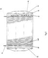
- the bracing of the multi-cell battery is shown in FIG. 2 as a second construction detail according to the invention.
- the force is applied via the tightening torque of the tie bolts 11 .
- the pressure elements 14 Through the end plate 13 through the pressure elements 14 , the individual different plates pressed between the end plates 12 and 13 .
- the pressure elements 14 such as disc springs, serve to maintain the compressive stress, within a tolerable force-displacement range characterized by the spring characteristic, with different expansion of the materials due to heating or swelling.
- the insulating plate 15 and the current tapping plate 16 are used in addition to their function as described below with regard to an equalized area distribution, the pressure force transmitted by the pressure elements 14 .
- the pressure elements 14 By means of the pressure elements 14 arranged centrally in the surface, it is possible to distribute the compressive force to the bipolar plates in such a way that the risk of detachment of contact with the following plates is prevented by the internal overpressure.
- the insulating plate 17 has the task of guiding the incoming and outgoing fluid and gas flows between the connections 18 and the main supply channels of the bipolar plates.
- the thickness and thus the weight could be reduced further by using electrically highly conductive materials.
- the contact resistance is reduced in these plates with a noble metal coating.
- the mass of the multi-cell battery could be reduced considerably through the consistent use of plastics and an optimal design, mainly with the end plates 12 and 13 and the frame 2 .
- Typical performances of the electrochemical multi-cell battery are moving in the range of 1 to 100 kW, with 5 to 200 cells per battery. Power density over 500 W / kg and over 500 W / dm3 can be achieved. Both hydrogen and reformer gas or oxygen or air can be used as reaction gases.
Landscapes
- Life Sciences & Earth Sciences (AREA)
- Engineering & Computer Science (AREA)
- Manufacturing & Machinery (AREA)
- Sustainable Development (AREA)
- Sustainable Energy (AREA)
- Chemical & Material Sciences (AREA)
- Chemical Kinetics & Catalysis (AREA)
- Electrochemistry (AREA)
- General Chemical & Material Sciences (AREA)
- Fuel Cell (AREA)
Abstract
Description
- Die Erfindung betrifft eine elektrochemische Mehrzellenbatterie mit Polymerelektrolytmembranen, welche insbesondere durch hohe Leistungsdichten gekennzeichnet ist.
- Für viele Anwendungen ist es erforderlich nach konstruktiven und werkstoffspezifischen Lösungen zu suchen, welche die derzeitig verfügbare volumenbezogene Leistungsdichte von rund 180 W/l deutlich erhöhen. Für eine erfolgreiche Akzeptanz auf dem Energiewandlermarkt genügt nicht allein die Umweltfreundlichkeit der Anlage, sondern sie muß auch in Masse und Bauvolumen gegenüber bisherigen Systemen mit fossilen Energieträgern konkurrenzfähig sein.
- Die konstruktiven und stofflichen Grenzen einer elektrochemischen Mehrzellenbatterie werden einmal gesetzt durch die erreichbare energetisch sinnvolle Leistungsdichte der Polymerelektrolytmembran (derzeit bei H₂/Luft-Betrieb bei etwa 1 W/cm²), welche die Größe der Reaktionsfläche vorschreibt, zum anderen die mechanischen Anforderungen an Festigkeit, Stabilität und Dichtigkeit und die elektrischen Einflußfaktoren wie spezifische Widerstände und Kontaktwiderstände sowie die chemische und thermische Beständigkeit der verwendeten Materialien.
- Da der Wirkungsgrad bei der Energieumwandlung von elektrochemischen Mehrzellenbatterien unter 100 % liegt, kommt der Kühlung der Zelle eine große Bedeutung zu. Um eine hohe Leistungsdichte zu erzielen, muß neben einer leichtgewichtigen Bauausführung eine möglichst homogene Kühlung gewährleistet werden.
- Dies hat zur Folge, daß auf engsten Raum möglichst viel Kühlmittelmasse erforderlich ist und vermehrte Umwälzung durch eine verlustarme Strömungsgeometrie stattfinden muß.
- Analog gelten für die Gasräume in elektrochemischen Zellen gleiche Folgerungen. Hier ist die Masse an Gas und dessen gleichmäßige Verteilung im Bereich der Reaktionsfläche und der angrenzenden Kanäle ein Maß für die Leistungsfähigkeit und Dynamik der Zelle, um auf schnelle Änderungen des Leistungsbedarfs der angeschlossenen Verbraucher zu reagieren. Desweiteren wird bei größeren Druckverlusten in den Kanälen, durch die dadurch benötigten höheren Verdichterleistungen für die Reaktanten, die Energieausbeute des Systems verringert.
- Bei aktuellen Ausführungen wird die Bipolare Platte (stromleitende Platte, welche auf der einen Fläche den Wasserstoffgasraum und auf der gegenüberliegenden Fläche den Luftraum eingearbeitet hat) vollständig aus einem elektrisch leitenden und korrosionsstabilen Material, wie z.B. Graphit, hergestellt. Eine wesentliche Anforderung an die Konstruktion einer elektrochemischen Mehrzellenbatterie sind neben der Leistungsdichte auch die Herstellkosten, die durch die Menge und Verarbeitung des verwendeten Materials bestimmt werden.
- Zur Gewährleistung eines effektiven und sicheren Betriebes der elektrochemischen Mehrzellenbatterie ist es notwendig, auch unter verschiedenen Betriebszuständen wie variablen Druck und Temperatur, eine homogenen Anpreßdruck der Platten aufeinander und eine ausreichende Dichtigkeit zueinander zu ermöglichen. Bisherige praktische Umsetzungen dieser Anforderungen zielen dahin, Anordnungen von Tellerfederpaketen koaxial auf den Zugankerschrauben und eventuell zusätzlich eine hydraulische oder pneumatische Druckeinheit im Flächenzentrum der Endplatten unterzubringen. Andere Lösungen sind federnde Draht oder Blechstrukturen, die in den Kühlmittelräumen die Druckspannungen und den elektrischen Strom weiterleiten.
- Aufgabe der Erfindung ist es, eine elektrochemische Mehrzellenbatterie mit Polymerelektrolytenmembranen zu schaffen, die eine wesentlich höhere Leistungsdichte durch eine optimierte Bauweise bei gleichzeitiger Berücksichtigung der sonstigen Anforderungen an eine elektrochemische Mehrzellenbatterie aufweist, als bestehende Ausführungen.
- Diese Aufgabe der Erfindung wird durch den Gegenstand des Hauptanspruchs gelöst.
Die Unteransprüche betreffen Ausgestaltungen der Erfindung. - Anhand von zwei Figuren wird der Gegenstand der Erfindung näher erläutert.
- Es zeigen:
- Fig. 1
- einen Querschnitt einer bipolaren Platte,
- Fig. 2
- eine Mehrzellenbatterie.
- Die Bipolare Platte der elektrochemischen Zelle besteht aus einem Rahmen 2 aus einem Kunststoff, wie z.B. Polycarbonat, und zwei stromleitenden Platten 1, z.B. aus Graphit oder Titan; Fig. 1 zeigt einen Querschnitt dieser Platteneinheit. In den Kunststoffrahmen 2 sind die Gasversorgungskanäle und Gasverteilung mittels Vorkammern 4, die Kühlmittelversorgung und Verteilung 6 und die Führungen für die Zugankerschraube integriert. Dieser Rahmen wird zwischen die gegeneinander gelegten stromleitenden Platten 1 mit Hilfe einer Dichtungsmasse oder Klebstoffes 7 elastisch eingeklebt. Die stromleitenden Platten 1 entsprechen in ihren Außenabmessungen der Größe der Reaktionsfläche und haben jeweils auf einer Seite einen Gasraum 3 und auf der anderen Seite einen Raum für das Kühlmittel 5 vorgesehen. Die Abdichtung zu den beidseitigen folgenden Membran/Elektrodeneinheiten, innerhalb der Mehrzellenbatterie, erfolgt über Flachdichtungen aus einem Elastomer 8, wie z.B. Silikonkautschuk. Einen großen Vorteil bietet das Rahmenkonzept durch seine nach außen hin elektrisch und thermisch isolierenden Eigenschaften. Es treten keine spannungsführenden Teile der Bipolaren Platten an die Oberfläche der Mehrzellenbatterie und die thermische Isolierung unterstützt die gleichmäßige Temperaturverteilung über die Reaktionsfläche im Inneren.
- Als zweites erfindungsgemäßes Konstruktionsdetail ist die Verspannung der Mehrzellenbatterie in Fig. 2 dargestellt. Die Krafteinleitung erfolgt über das Anzugsmoment der Zugankerschrauben 11. Durch die Endplatte 13 weiter über die Druckelemente 14, werden die einzelnen unterschiedlichen Platten zwischen die Endplatten 12 und 13 zusammengepreßt. Die Druckelemente 14, wie z.B. Tellerfedern, dienen hierbei zur Erhaltung der Druckspannung, innerhalb eines durch die Federkennlinie gekennzeichneten tolerierbaren Kraft-Weg-Bereiches, bei unterschiedlicher Ausdehnung der Materialien durch Erwärmung oder Aufquellung.
- Desweiteren ist die Isolierplatte 15 und die Stromabgriffplatte 16 neben ihrer der Bezeichnung nach zu folgenden Aufgabe auch hinsichtlich einer egalisierten flächigen Verteilung, der von den Druckelementen 14 übertragenen Druckkraft, im Einsatz.
- Durch die flächenzentral angeordneten Druckelemente 14 gelingt es, die Druckkraft auf die Bipolaren Platten derart zu verteilen, daß die Gefahr der Ablösung des Kontaktes zu den folgenden Platten durch den inneren Überdruck verhindert wird.
Die Isolierplatte 17 hat neben der elektrischen Isolierung die Aufgabe, die ab- und ankommenden Fluid- und Gasströme zwischen den Anschlüssen 18 und den Hauptversorgungskanälen der Bipolaren Platten zu leiten.
Bei den Stromabgriffplatten 16 konnte durch die Verwendung elektrisch hochleitfähigen Materialien die Dicke und damit das Gewicht weiter reduziert werden, zusätzlich wird bei diesen Platten mit einer Edelmetallbeschichtung der Kontaktwiderstand verringert.
Durch eine konsequente Anwendung von Kunststoffen und eine optimale Gestaltung, in der Hauptsache bei den Endplatten 12 und 13 sowie den Rahmen 2, konnte die Masse der Mehrzellenbatterie erheblich reduziert werden. - Typische Leistungen der elektrochemischen Mehrzellenbatterie bewegen sich in dem Bereich von 1 bis 100 kW, mit 5 bis 200 Zellen pro Batterie. Leistungsdichte über 500 W/kg und über 500 W/dm³ können erreicht werden. Als Reaktionsgase können sowohl Wasserstoff als auch Reformergas beziehungsweise Sauerstoff oder Luft verwendet werden.
Claims (12)
- Elektrochemische Mehrzellenbatterie mit Polymerelektrolytmembranen, dadurch gekennzeichnet, daß eine kompakte und kostengünstige Bauweise und dadurch hohe Leistungsdichten erreicht werden, indem eine Bipolare Platte (1,2) in Rahmenbauweise ausgeführt ist und die Verspannung und Anpreßung in die vorhandenen Bauteile raumsparend integriert ist.
- Elektrochemische Mehrsellenbatterie nach Anspruch 1, dadurch gekennzeichnet, daß die Gas- und Kühlmittelversorgungskanäle und/oder die Gas (4)- und Kühlmittelvorkammern (6) und die Zugankerschrauben (11) in dem Rahmen (2) aus einem Kunststoff, wie z.B. Polycarbonat oder Silikon, untergebracht sind.
- Elektrochemische Mehrzellenbatterie nach Anspruch 1, dadurch gekennzeichnet, daß die Bipolare Platte im Bereich der Reaktionsfläche, das heißt die Platten (1), aus einem elektrisch leitenden und korrosionsstabilen Material, wie z.B. Graphit oder Titan, besteht.
- Elektrochemische Mehrzellenbatterie nach Anspruch 1, dadurch gekennzeichnet, daß die Zugankerschrauben (11) innenliegend in den Rahmen (2) aus Kunststoff integriert sind.
- Elektrochemische Mehrzellenbatterie nach Anspruch 1, dadurch gekennzeichnet, daß die Abdichtung (7) zwischen den Platten (1) und dem Rahmen (2) durch eine elastische Dichtungs- bzw. Klebestoffmasse, wie z.B. Polydimethylsiloxan (Silikonkautschuk), ein fluorierter Polydimethylsiloxan oder ein Epoxidharz, erfolgt.
- Elektrochemische Mehrzellenbatterie nach Anspruch 1, dadurch gekennzeichnet, daß die Isolierplatte (17) die Verteilung der Gase und des Kühlmittels von den Anschlüssen (18) zu den Versorgungskanälen beinhaltet.
- Elektrochemische Mehrzellenbatterie nach Anspruch 1, dadurch gekennzeichnet, daß in die Isolierplatte (15) die flächenzentral angeordneten Druckelemente (14), wie z.B. Tellerfedern, mit einbezogen sind, welche eine homogene Anpreßung der Platten aufeinander gewährleisten.
- Elektrochemische Mehrzellenbatterie nach Anspruch 1, dadurch gekennzeichnet, daß die Endplatten (12, 13) aus einem hochfesten Werkstoff mit geringer spezifischer Dichte, wie z.B. Aluminium-Legierung, Titan-Legierung und Faserverbundwerkstoff nach dem Prinzip der direkten und kurzen Krafteinleitung gefertigt sind, beziehungsweise auch in Honigwabenstrukturen ausgeführt sein können.
- Elektrochemische Mehrzellenbatterie nach Anspruch 1, dadurch gekennzeichnet, daß die Stromabgriffsplatten (16) aus einem beschichteten elektrisch hochleitfähigen Material, wie z.B. Kupfer, Kupferlegierungen oder Aluminiumlegierungen, welche mit Gold oder Platinmetallen beschichtet sind, bestehen.
- Elektrochemische Mehrzellenbatterie nach Anspruch 1 bis 9, dadurch gekennzeichnet, daß über die Zugankerschrauben (11) die Vorspannung der obengenannten Platten aufeinander erfolgt und der Ausgleich der Druckunterschiede und der thermischen Längenausdehnung über die Druckelemente (14) und zum Teil über die Dichtungen (7, 8) geschieht, gleichzeitig auch der elektrische Kontakt der stromleitenden Platten (1) zwischen den Stromabgriffplatten (16) gewährleistet wird.
- Elektrochemische Mehrzellenbatterie nach Anspruch 1 bis 10, dadurch gekennzeichnet, daß die elektrochemische Mehrzellenbatterie eine Brennstoffzellenbatterie ist.
- Elektrochemische Mehrzellenbatterie nach Anspruch 11, dadurch gekennzeichnet, daß als Reaktanten Sauerstoff oder Luft und Wasserstoff oder Reformiergas verwendet wird.
Applications Claiming Priority (2)
| Application Number | Priority Date | Filing Date | Title |
|---|---|---|---|
| DE4309976 | 1993-03-26 | ||
| DE4309976A DE4309976A1 (de) | 1993-03-26 | 1993-03-26 | Elektrochemische Mehrzellenbatterie |
Publications (2)
| Publication Number | Publication Date |
|---|---|
| EP0620609A1 true EP0620609A1 (de) | 1994-10-19 |
| EP0620609B1 EP0620609B1 (de) | 1997-08-06 |
Family
ID=6484007
Family Applications (1)
| Application Number | Title | Priority Date | Filing Date |
|---|---|---|---|
| EP94104029A Expired - Lifetime EP0620609B1 (de) | 1993-03-26 | 1994-03-16 | Elektrochemische Mehrzellenbatterie |
Country Status (2)
| Country | Link |
|---|---|
| EP (1) | EP0620609B1 (de) |
| DE (2) | DE4309976A1 (de) |
Cited By (17)
| Publication number | Priority date | Publication date | Assignee | Title |
|---|---|---|---|---|
| WO1995028010A1 (en) * | 1994-04-06 | 1995-10-19 | Ballard Power Systems Inc. | Electrochemical fuel cell stack with compact, centrally disposed compression mechanism |
| EP0780916A1 (de) * | 1995-12-22 | 1997-06-25 | General Motors Corporation | Korrosionsbeständige elektrische Kontaktelemente für Brennstoffzellen mit einem Polymerelektrolyt-Membran |
| WO1998022990A1 (en) * | 1996-11-19 | 1998-05-28 | Ballard Power Systems Inc. | Electrochemical fuel cell stack with compression bands |
| EP0914922A1 (de) * | 1997-10-29 | 1999-05-12 | Aisin Takaoka Co., Ltd. | Silikonharz - Metal Verbindungsgegenstand |
| EP0750797A4 (de) * | 1994-02-23 | 2000-02-09 | William R Richards | Brennstoffzelle mit gleichmässiger druckspannungsverteilung über aktive fläche |
| WO2003017400A1 (de) * | 2001-08-14 | 2003-02-27 | Deutsche Titan Gmbh | Kollektorplattensatz für brennstoff- oder andere elektrochemische zellen sowie verfahren zur herstellung solcher kollektorplatten |
| WO2002041430A3 (de) * | 2000-11-17 | 2004-02-19 | Siemens Ag | Brennstoffzellenanlage |
| US6828057B2 (en) * | 2002-04-29 | 2004-12-07 | Energy Conversion Devices, Inc. | Fuel cell with framed electrodes |
| WO2004112178A2 (de) | 2003-06-18 | 2004-12-23 | Reinz-Dichtungs-Gmbh | Elektrochemische anordnung mit elastischer verteilungsstruktur |
| WO2004091025A3 (de) * | 2003-04-06 | 2005-03-10 | Proton Motor Fuel Cell Gmbh | Brennstoffzelle und brennstoffzellenstapel mit äusserer medienzuführung |
| WO2004077587A3 (de) * | 2003-02-27 | 2005-04-07 | Forschungszentrum Juelich Gmbh | Herstellung eines hochtemperatur-brennstoffzellenstapels |
| US6926986B2 (en) * | 2002-04-29 | 2005-08-09 | Energy Conversion Devices | Fuel cell with encapsulated electrodes |
| US6989216B2 (en) * | 2002-04-29 | 2006-01-24 | Texaco Ovonic Fuel Cell Llc | Fuel cell with overmolded electrode assemblies |
| DE10216306B4 (de) * | 2002-04-14 | 2008-06-12 | Sgl Carbon Ag | Verfahren zur Herstellung einer Kontaktplatte für eine elektrochemische Zelle sowie deren Verwendungen |
| DE112008000024B4 (de) * | 2007-06-06 | 2012-11-08 | Panasonic Corporation | Polymerelektrolyt-Brennstoffzelle |
| CN105655609A (zh) * | 2014-11-26 | 2016-06-08 | 中国科学院大连化学物理研究所 | 一种用于燃料电池电堆装配的内定位结构 |
| CN109947154A (zh) * | 2019-02-28 | 2019-06-28 | 深圳市新浦自动化设备有限公司 | 电池化成夹具控温装置及电池化成控温方法 |
Families Citing this family (22)
| Publication number | Priority date | Publication date | Assignee | Title |
|---|---|---|---|---|
| DE19501783C2 (de) * | 1995-01-21 | 1999-11-18 | Angermeier S Schaedlingsbekaem | Verfahren zum Begasen eines Behandlungsraumes |
| DE19534047C1 (de) * | 1995-09-14 | 1996-12-19 | Mtu Friedrichshafen Gmbh | Anodenstromkollektor und Verfahren zur Herstellung eines Anodenstromkollektors |
| DE69720451T2 (de) * | 1996-06-25 | 2004-01-15 | Du Pont | Polymerelektrolyt-membran-brennstoffzelle mit bipolarem platte mit einstückig, leitendem einsatzteil |
| DE19713250C2 (de) * | 1997-03-29 | 2002-04-18 | Ballard Power Systems | Elektrochemischer Energiewandler mit Polymerelektrolytmembran |
| DE19715256C1 (de) * | 1997-04-12 | 1998-08-27 | Forschungszentrum Juelich Gmbh | Zweiteiliges Verbindungselement für Brennstoffzellen |
| DE19962682A1 (de) * | 1999-12-23 | 2001-07-05 | Siemens Ag | Brennstoffzellenstack, die Verwendung eines Brennstoffzellenstacks und ein Verfahren zur Montage eines Brennstoffzellenstacks |
| CA2345852C (en) | 2000-05-02 | 2008-11-18 | Honda Giken Kogyo Kabushiki Kaisha | Fuel cell having sealant for sealing a solid polymer electrolyte membrane |
| DE10056539C2 (de) * | 2000-11-15 | 2002-10-24 | Mtu Friedrichshafen Gmbh | Brennstoffzellenanordnung |
| DE10058381B4 (de) * | 2000-11-24 | 2008-07-03 | Inhouse Engineering Gmbh | Modularer multifunktionaler Brennstoffzellenstapel mit Polymer-Eektrolyt-Membranen (PEM) |
| US6777127B2 (en) | 2001-06-22 | 2004-08-17 | Ballard Power Systems Inc. | Systems, apparatus and methods for bonding and/or sealing electrochemical cell elements and assemblies |
| DE20111941U1 (de) * | 2001-07-13 | 2002-11-21 | Sachsenring Fahrzeugtechnik GmbH, 08058 Zwickau | Vorrichtung zum Spannen von Brennstoffzellenstapeln |
| DE10151452A1 (de) * | 2001-10-18 | 2003-04-30 | Behr Gmbh & Co | Brennstoffzellenstapel |
| DE10158772C1 (de) * | 2001-11-23 | 2003-06-26 | Reinz Dichtungs Gmbh & Co Kg | Brennstoffzellensystem |
| DE10158771C2 (de) * | 2001-11-23 | 2003-09-18 | Reinz Dichtungs Gmbh & Co Kg | Brennstoffzellensystem |
| DE10203612C1 (de) | 2002-01-23 | 2003-06-26 | Reinz Dichtungs Gmbh & Co Kg | Brennstoffzellenpaket sowie dafür geeignete bipolare Platte |
| DE10219456B4 (de) * | 2002-04-30 | 2005-10-13 | Mtu Cfc Solutions Gmbh | Brennstoffzelle und Verfahren zur Herstellung einer solchen |
| US7718293B2 (en) | 2002-10-14 | 2010-05-18 | Reinz-Dichtungs-Gmbh | Electrochemical system with fluid passage integrated within a sealing bead |
| DE102009049043A1 (de) * | 2009-10-12 | 2011-04-14 | Li-Tec Battery Gmbh | Zellblock mit seitlicher Abstützung der Zellen |
| KR20120105331A (ko) * | 2011-03-15 | 2012-09-25 | 현대자동차주식회사 | 내부식성이 향상된 연료전지 스택 |
| GB201207759D0 (en) * | 2012-05-03 | 2012-06-13 | Imp Innovations Ltd | Fuel cell |
| DE202012104081U1 (de) | 2012-10-23 | 2013-01-29 | Icm - Institut Chemnitzer Maschinen- Und Anlagenbau E.V. | Einlaminierter Akkumulator, vorzugsweise zum Einsatz in Elektrofahrzeugen |
| DE102021113960A1 (de) * | 2021-05-31 | 2022-12-01 | Audi Aktiengesellschaft | Brennstoffzelle mit Elastomerschichten und Verfahren zur Herstellung einer Brennstoffzelle |
Citations (12)
| Publication number | Priority date | Publication date | Assignee | Title |
|---|---|---|---|---|
| FR1285926A (fr) * | 1959-11-03 | 1962-03-02 | Thomson Houston Comp Francaise | Batterie de piles à combustible |
| US4124478A (en) * | 1977-02-07 | 1978-11-07 | Tsien Hsue C | Thin sheet apparatus and a fluid flow device |
| GB2039954A (en) * | 1979-01-02 | 1980-08-20 | Gen Electric | Low cost bipolar current collector separator for electrochemical cells |
| DE3321984A1 (de) * | 1982-06-23 | 1983-12-29 | General Electric Co., Schenectady, N.Y. | Brennstoffzellenbatterie mit verbesserter membrankuehlung |
| EP0155695A2 (de) * | 1984-03-23 | 1985-09-25 | Hitachi, Ltd. | Brennstoffzelle |
| JPS61225779A (ja) * | 1985-03-29 | 1986-10-07 | Shin Kobe Electric Mach Co Ltd | 液体燃料電池 |
| JPS61230273A (ja) * | 1985-04-03 | 1986-10-14 | Sanyo Electric Co Ltd | 燃料電池のスタツク端板 |
| JPS61248368A (ja) * | 1985-04-25 | 1986-11-05 | Mitsubishi Electric Corp | 積層形燃料電池の締付装置 |
| US4769297A (en) * | 1987-11-16 | 1988-09-06 | International Fuel Cells Corporation | Solid polymer electrolyte fuel cell stack water management system |
| US5002841A (en) * | 1990-01-10 | 1991-03-26 | Globe-Union Inc. | Composite end block for a battery |
| US5110691A (en) * | 1991-01-16 | 1992-05-05 | International Fuel Cells Corporation | Fuel cell component sealant |
| US5187025A (en) * | 1992-02-03 | 1993-02-16 | Analytic Power Corp. | Unitized fuel cell structure |
-
1993
- 1993-03-26 DE DE4309976A patent/DE4309976A1/de not_active Ceased
-
1994
- 1994-03-16 DE DE59403595T patent/DE59403595D1/de not_active Expired - Fee Related
- 1994-03-16 EP EP94104029A patent/EP0620609B1/de not_active Expired - Lifetime
Patent Citations (12)
| Publication number | Priority date | Publication date | Assignee | Title |
|---|---|---|---|---|
| FR1285926A (fr) * | 1959-11-03 | 1962-03-02 | Thomson Houston Comp Francaise | Batterie de piles à combustible |
| US4124478A (en) * | 1977-02-07 | 1978-11-07 | Tsien Hsue C | Thin sheet apparatus and a fluid flow device |
| GB2039954A (en) * | 1979-01-02 | 1980-08-20 | Gen Electric | Low cost bipolar current collector separator for electrochemical cells |
| DE3321984A1 (de) * | 1982-06-23 | 1983-12-29 | General Electric Co., Schenectady, N.Y. | Brennstoffzellenbatterie mit verbesserter membrankuehlung |
| EP0155695A2 (de) * | 1984-03-23 | 1985-09-25 | Hitachi, Ltd. | Brennstoffzelle |
| JPS61225779A (ja) * | 1985-03-29 | 1986-10-07 | Shin Kobe Electric Mach Co Ltd | 液体燃料電池 |
| JPS61230273A (ja) * | 1985-04-03 | 1986-10-14 | Sanyo Electric Co Ltd | 燃料電池のスタツク端板 |
| JPS61248368A (ja) * | 1985-04-25 | 1986-11-05 | Mitsubishi Electric Corp | 積層形燃料電池の締付装置 |
| US4769297A (en) * | 1987-11-16 | 1988-09-06 | International Fuel Cells Corporation | Solid polymer electrolyte fuel cell stack water management system |
| US5002841A (en) * | 1990-01-10 | 1991-03-26 | Globe-Union Inc. | Composite end block for a battery |
| US5110691A (en) * | 1991-01-16 | 1992-05-05 | International Fuel Cells Corporation | Fuel cell component sealant |
| US5187025A (en) * | 1992-02-03 | 1993-02-16 | Analytic Power Corp. | Unitized fuel cell structure |
Non-Patent Citations (4)
| Title |
|---|
| PATENT ABSTRACTS OF JAPAN vol. 11, no. 70 (E - 485)<2517> 3 March 1987 (1987-03-03) * |
| PATENT ABSTRACTS OF JAPAN vol. 11, no. 73 (E - 486)<2520> 5 March 1987 (1987-03-05) * |
| PATENT ABSTRACTS OF JAPAN vol. 11, no. 95 (E - 492)<2542> 25 March 1987 (1987-03-25) * |
| R. H. BLACKMER ET AL: "Ion-exchange membrane", SAE JOURNAL, vol. 70, no. 1, January 1962 (1962-01-01), pages 82 - 86, XP002044995 * |
Cited By (25)
| Publication number | Priority date | Publication date | Assignee | Title |
|---|---|---|---|---|
| EP0750797A4 (de) * | 1994-02-23 | 2000-02-09 | William R Richards | Brennstoffzelle mit gleichmässiger druckspannungsverteilung über aktive fläche |
| WO1995028010A1 (en) * | 1994-04-06 | 1995-10-19 | Ballard Power Systems Inc. | Electrochemical fuel cell stack with compact, centrally disposed compression mechanism |
| USRE37284E1 (en) | 1995-12-22 | 2001-07-17 | General Motors Corporation | Corrosion resistant PEM fuel cell |
| EP0780916A1 (de) * | 1995-12-22 | 1997-06-25 | General Motors Corporation | Korrosionsbeständige elektrische Kontaktelemente für Brennstoffzellen mit einem Polymerelektrolyt-Membran |
| GB2333890A (en) * | 1996-11-19 | 1999-08-04 | Ballard Power Systems | Electrochemical fuel cell stack with compression bands |
| US5993987A (en) * | 1996-11-19 | 1999-11-30 | Ballard Power Systems Inc. | Electrochemical fuel cell stack with compression bands |
| WO1998022990A1 (en) * | 1996-11-19 | 1998-05-28 | Ballard Power Systems Inc. | Electrochemical fuel cell stack with compression bands |
| GB2333890B (en) * | 1996-11-19 | 2000-05-24 | Ballard Power Systems | Electrochemical fuel cell stack with compression bands |
| EP0914922A1 (de) * | 1997-10-29 | 1999-05-12 | Aisin Takaoka Co., Ltd. | Silikonharz - Metal Verbindungsgegenstand |
| US6153326A (en) * | 1997-10-29 | 2000-11-28 | Aisin Takaoka Co., Ltd. | Silicone resin-metal composite |
| WO2002041430A3 (de) * | 2000-11-17 | 2004-02-19 | Siemens Ag | Brennstoffzellenanlage |
| WO2003017400A1 (de) * | 2001-08-14 | 2003-02-27 | Deutsche Titan Gmbh | Kollektorplattensatz für brennstoff- oder andere elektrochemische zellen sowie verfahren zur herstellung solcher kollektorplatten |
| DE10216306B4 (de) * | 2002-04-14 | 2008-06-12 | Sgl Carbon Ag | Verfahren zur Herstellung einer Kontaktplatte für eine elektrochemische Zelle sowie deren Verwendungen |
| US6828057B2 (en) * | 2002-04-29 | 2004-12-07 | Energy Conversion Devices, Inc. | Fuel cell with framed electrodes |
| US6926986B2 (en) * | 2002-04-29 | 2005-08-09 | Energy Conversion Devices | Fuel cell with encapsulated electrodes |
| US6989216B2 (en) * | 2002-04-29 | 2006-01-24 | Texaco Ovonic Fuel Cell Llc | Fuel cell with overmolded electrode assemblies |
| WO2004077587A3 (de) * | 2003-02-27 | 2005-04-07 | Forschungszentrum Juelich Gmbh | Herstellung eines hochtemperatur-brennstoffzellenstapels |
| WO2004091025A3 (de) * | 2003-04-06 | 2005-03-10 | Proton Motor Fuel Cell Gmbh | Brennstoffzelle und brennstoffzellenstapel mit äusserer medienzuführung |
| WO2004112178A3 (de) * | 2003-06-18 | 2005-06-30 | Reinz Dichtungs Gmbh | Elektrochemische anordnung mit elastischer verteilungsstruktur |
| WO2004112178A2 (de) | 2003-06-18 | 2004-12-23 | Reinz-Dichtungs-Gmbh | Elektrochemische anordnung mit elastischer verteilungsstruktur |
| DE112008000024B4 (de) * | 2007-06-06 | 2012-11-08 | Panasonic Corporation | Polymerelektrolyt-Brennstoffzelle |
| US8343688B2 (en) | 2007-06-06 | 2013-01-01 | Panasonic Corporation | Polymer electrolyte fuel cell having a fastening structure including elastic members |
| CN105655609A (zh) * | 2014-11-26 | 2016-06-08 | 中国科学院大连化学物理研究所 | 一种用于燃料电池电堆装配的内定位结构 |
| CN109947154A (zh) * | 2019-02-28 | 2019-06-28 | 深圳市新浦自动化设备有限公司 | 电池化成夹具控温装置及电池化成控温方法 |
| CN109947154B (zh) * | 2019-02-28 | 2023-05-23 | 深圳市新浦自动化设备有限公司 | 电池化成夹具控温装置及电池化成控温方法 |
Also Published As
| Publication number | Publication date |
|---|---|
| DE59403595D1 (de) | 1997-09-11 |
| DE4309976A1 (de) | 1994-09-29 |
| EP0620609B1 (de) | 1997-08-06 |
Similar Documents
| Publication | Publication Date | Title |
|---|---|---|
| EP0620609B1 (de) | Elektrochemische Mehrzellenbatterie | |
| DE69929731T2 (de) | Polymerelektrolyt-Brennstoffzelle | |
| DE102008026858B4 (de) | Brennstoffzellensystem mit einem nachgiebigen Riemenwerk zur Beibehaltung von Kompression der Brennstoffzellen | |
| DE10213558B4 (de) | Brennstoffzellenstapel | |
| US20020045086A1 (en) | Separator for fuel cell | |
| DE69503648T2 (de) | Brennstoffzellenstapel mit kompressionsvorrichtung verbunden mit innen angeordneten sammelkanälen | |
| EP0797847B1 (de) | Polymerelektrolyt-membran-brennstoffzelle | |
| DE3779615T2 (de) | Brennstoffzellenstapel mit enddruckplatten. | |
| DE102004037678A1 (de) | Brennstoffzellenstapel | |
| DE2729640A1 (de) | Batterie aus einer mehrzahl elektrochemischer zellen | |
| WO2003096447A1 (en) | Fuel cell stack having an improved pressure plate and current collector | |
| DE10340215A1 (de) | Polymerelektrolytmembran-Brennstoffzelle und bipolare Platte | |
| DE102007051568A1 (de) | Brennstoffzellenstapel-Kompressionshalterungssystem mit externen Federn | |
| US10396366B2 (en) | Bipolar plate having a polymeric coating | |
| DE102016004306A1 (de) | Brennstoffzellenstapel, Brennstoffzellensystem, Fahrzeug und Verfahren zum Fertigen eines Brennstoffzellenstapels | |
| DE102013020860A1 (de) | Zellblock für eine Batterie | |
| DE102020209663A1 (de) | Brennstoffzelleneinheit | |
| WO2002005368A1 (de) | Hochtemperaturbrennstoffzelle | |
| DE102007022202B4 (de) | Brennstoffzellenstapel mit einer nichtpermeablen Beilage mit niedrigem Kontaktwiderstand | |
| EP2965378A2 (de) | Kompressionssystem für einen elektrochemischen stapel | |
| US20240258548A1 (en) | Enclosed fuel cell stack row | |
| US20050106444A1 (en) | Fuel cell and separator for cooling used therein | |
| DE102007039934A1 (de) | Brennstoffzellenstapel und Wasserstoffversorgung mit einem Keramikheizer mit positivem Temperaturkoeffizienten | |
| EP1627445B1 (de) | Elektrolyse- bzw. brennstoffzelle mit druckkissen und verbessertem übergangswiderstand | |
| DE102007059449B4 (de) | Brennstoffzellensystem und Kompressionshalterungssystem mit planaren Streifen |
Legal Events
| Date | Code | Title | Description |
|---|---|---|---|
| PUAI | Public reference made under article 153(3) epc to a published international application that has entered the european phase |
Free format text: ORIGINAL CODE: 0009012 |
|
| AK | Designated contracting states |
Kind code of ref document: A1 Designated state(s): DE FR GB IT |
|
| 17P | Request for examination filed |
Effective date: 19950413 |
|
| 17Q | First examination report despatched |
Effective date: 19960124 |
|
| GRAG | Despatch of communication of intention to grant |
Free format text: ORIGINAL CODE: EPIDOS AGRA |
|
| GRAH | Despatch of communication of intention to grant a patent |
Free format text: ORIGINAL CODE: EPIDOS IGRA |
|
| GRAH | Despatch of communication of intention to grant a patent |
Free format text: ORIGINAL CODE: EPIDOS IGRA |
|
| GRAA | (expected) grant |
Free format text: ORIGINAL CODE: 0009210 |
|
| AK | Designated contracting states |
Kind code of ref document: B1 Designated state(s): DE FR GB IT |
|
| GBT | Gb: translation of ep patent filed (gb section 77(6)(a)/1977) |
Effective date: 19970814 |
|
| REF | Corresponds to: |
Ref document number: 59403595 Country of ref document: DE Date of ref document: 19970911 |
|
| ET | Fr: translation filed | ||
| PLBE | No opposition filed within time limit |
Free format text: ORIGINAL CODE: 0009261 |
|
| STAA | Information on the status of an ep patent application or granted ep patent |
Free format text: STATUS: NO OPPOSITION FILED WITHIN TIME LIMIT |
|
| 26N | No opposition filed | ||
| REG | Reference to a national code |
Ref country code: GB Ref legal event code: 732E |
|
| REG | Reference to a national code |
Ref country code: GB Ref legal event code: IF02 |
|
| PGFP | Annual fee paid to national office [announced via postgrant information from national office to epo] |
Ref country code: IT Payment date: 20080327 Year of fee payment: 15 Ref country code: GB Payment date: 20080312 Year of fee payment: 15 |
|
| PGFP | Annual fee paid to national office [announced via postgrant information from national office to epo] |
Ref country code: FR Payment date: 20080311 Year of fee payment: 15 Ref country code: DE Payment date: 20080313 Year of fee payment: 15 |
|
| GBPC | Gb: european patent ceased through non-payment of renewal fee |
Effective date: 20090316 |
|
| REG | Reference to a national code |
Ref country code: FR Ref legal event code: TP |
|
| REG | Reference to a national code |
Ref country code: FR Ref legal event code: ST Effective date: 20091130 |
|
| REG | Reference to a national code |
Ref country code: FR Ref legal event code: CD Ref country code: FR Ref legal event code: CA |
|
| PG25 | Lapsed in a contracting state [announced via postgrant information from national office to epo] |
Ref country code: DE Free format text: LAPSE BECAUSE OF NON-PAYMENT OF DUE FEES Effective date: 20091001 |
|
| PG25 | Lapsed in a contracting state [announced via postgrant information from national office to epo] |
Ref country code: GB Free format text: LAPSE BECAUSE OF NON-PAYMENT OF DUE FEES Effective date: 20090316 Ref country code: FR Free format text: LAPSE BECAUSE OF NON-PAYMENT OF DUE FEES Effective date: 20091123 |
|
| PG25 | Lapsed in a contracting state [announced via postgrant information from national office to epo] |
Ref country code: IT Free format text: LAPSE BECAUSE OF NON-PAYMENT OF DUE FEES Effective date: 20090316 |