EP0620380B1 - Torsionschwingungsdämpfer und Methode zur Herstellung desselben - Google Patents
Torsionschwingungsdämpfer und Methode zur Herstellung desselben Download PDFInfo
- Publication number
- EP0620380B1 EP0620380B1 EP93106068A EP93106068A EP0620380B1 EP 0620380 B1 EP0620380 B1 EP 0620380B1 EP 93106068 A EP93106068 A EP 93106068A EP 93106068 A EP93106068 A EP 93106068A EP 0620380 B1 EP0620380 B1 EP 0620380B1
- Authority
- EP
- European Patent Office
- Prior art keywords
- annular
- roll
- housing
- wall
- spinning
- Prior art date
- Legal status (The legal status is an assumption and is not a legal conclusion. Google has not performed a legal analysis and makes no representation as to the accuracy of the status listed.)
- Expired - Lifetime
Links
Images


Classifications
-
- B—PERFORMING OPERATIONS; TRANSPORTING
- B21—MECHANICAL METAL-WORKING WITHOUT ESSENTIALLY REMOVING MATERIAL; PUNCHING METAL
- B21D—WORKING OR PROCESSING OF SHEET METAL OR METAL TUBES, RODS OR PROFILES WITHOUT ESSENTIALLY REMOVING MATERIAL; PUNCHING METAL
- B21D22/00—Shaping without cutting, by stamping, spinning, or deep-drawing
- B21D22/14—Spinning
- B21D22/16—Spinning over shaping mandrels or formers
-
- F—MECHANICAL ENGINEERING; LIGHTING; HEATING; WEAPONS; BLASTING
- F16—ENGINEERING ELEMENTS AND UNITS; GENERAL MEASURES FOR PRODUCING AND MAINTAINING EFFECTIVE FUNCTIONING OF MACHINES OR INSTALLATIONS; THERMAL INSULATION IN GENERAL
- F16F—SPRINGS; SHOCK-ABSORBERS; MEANS FOR DAMPING VIBRATION
- F16F15/00—Suppression of vibrations in systems; Means or arrangements for avoiding or reducing out-of-balance forces, e.g. due to motion
- F16F15/10—Suppression of vibrations in rotating systems by making use of members moving with the system
- F16F15/16—Suppression of vibrations in rotating systems by making use of members moving with the system using a fluid or pasty material
- F16F15/167—Suppression of vibrations in rotating systems by making use of members moving with the system using a fluid or pasty material having an inertia member, e.g. ring
- F16F15/173—Suppression of vibrations in rotating systems by making use of members moving with the system using a fluid or pasty material having an inertia member, e.g. ring provided within a closed housing
-
- F—MECHANICAL ENGINEERING; LIGHTING; HEATING; WEAPONS; BLASTING
- F16—ENGINEERING ELEMENTS AND UNITS; GENERAL MEASURES FOR PRODUCING AND MAINTAINING EFFECTIVE FUNCTIONING OF MACHINES OR INSTALLATIONS; THERMAL INSULATION IN GENERAL
- F16F—SPRINGS; SHOCK-ABSORBERS; MEANS FOR DAMPING VIBRATION
- F16F2226/00—Manufacturing; Treatments
- F16F2226/04—Assembly or fixing methods; methods to form or fashion parts
- F16F2226/045—Press-fitting
-
- F—MECHANICAL ENGINEERING; LIGHTING; HEATING; WEAPONS; BLASTING
- F16—ENGINEERING ELEMENTS AND UNITS; GENERAL MEASURES FOR PRODUCING AND MAINTAINING EFFECTIVE FUNCTIONING OF MACHINES OR INSTALLATIONS; THERMAL INSULATION IN GENERAL
- F16F—SPRINGS; SHOCK-ABSORBERS; MEANS FOR DAMPING VIBRATION
- F16F2226/00—Manufacturing; Treatments
- F16F2226/04—Assembly or fixing methods; methods to form or fashion parts
- F16F2226/048—Welding
Definitions
- This invention relates to improvements in viscous torsional vibration dampers and is more particularly concerned with improving the reliability and lowering the cost of such dampers.
- Viscous torsional vibration dampers of the kind to which the present invention is directed have heretofore been successfully produced with cast ferrous, forged ferrous, stamped, and welded housings all machined to provide the desired dimensions, providing an axially opening annular working chamber within which is housed a complementary annular inertia mass ring and with a cover sealed across the axial opening of the housing for confining the inertia ring within the annular working chamber therein.
- Opposed surfaces of the inertia ring and the housing are in shear film spaced relation having regard to a viscous damping fluid substantially filling those spaces.
- Cast, forged, and stamped and welded housings require much machining, and therefore present a substantial cost factor in the dampers.
- the document US-A 3, 792, 683 discloses a housing of a torsional vibration damper.
- An annular inertia weight is rotatably mounted in a closed chamber and comprises an iron casting or other weighty material covered with a coating such as nylon, Teflon, bronze or the like.
- a coating such as nylon, Teflon, bronze or the like.
- the working chamber wall surfaces have to be machined in a separate operation. This problem is a general one and cannot be avoided with prior art dampers. Further, it may occur that because of those abrasion processes the damper is not dynamically balanced.
- a finishing device for spinning work is disclosed in Japanese abstract Vol. 6, number 224 (M 170) [1102] November 9, 1982.
- the side face of a work piece to be finished is pressed to the circumference, while a roller is swung and moved in parallel to the rotary shaft direction of the mandrel.
- U.S. Patent No. 4,872,369 discloses a tortional vibration damper according to the preamble of claim 8 and a method of making a tortional vibration damper according to the preamble of claim 1 and also according to the preamble of claim 5, contrary to the present invention defined by claim 1, claim 5 or claim 8, this document describes the roll spinning of the entire inside chamber walls 14, 15, 17 in a first step, and in a second step roll spinning outside surface of both the chamber base wall 14 and the annular outer axial wall 15 to form the chamber.
- An important object of the present invention is to overcome the disadvantages and problems encountered in respect to prior viscous torsional vibration dampers and methods of making the same and to provide a new and improved damper of this type and method of making the same.
- a further object of the present invention is to provide in such a damper a new and improved means for mounting the closure to the housing of the damper and for maintaining the integrity of the hermetic seal between the housing and the closure.
- a viscous torsional vibration damper of the kind operating on the shear film principle and having an annular channel shaped housing providing an annular working chamber within which is mounted an annular complementary inertia mass ring and a viscous damping fluid substantially filling shear film spaces between working surfaces of the inertia ring and confronting working surfaces of the housing within the chamber,
- the housing comprising a roll spun generally channel shaped annular shell having a generally axially facing base wall and spaced axially extending radially inner and radially outer walls and which walls provide said housing working surfaces; annular radius corners joining said walls; and wherein only said housing working surfaces of the axially facing base wall and radially inner wall need have a spinning roll work hardened burnished finish. Only the radially outer wall of the annular shell need be spin rolled to complete the channel shape.
- a further aim of the present invention is to provide a new and improved method of making torsional viscous vibration dampers having the new and improved construction aforesaid.
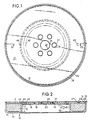
- a typical viscous torsional vibration damper sometimes referred to as a crankshaft damper, embodying the present invention, is depicted in Figs. 1 and 2.
- This damper comprises as its major components a one piece channel shaped housing 10 defining an annular working chamber 11, within which is housed a complementary inertia member ring 12, and with the axially open side of the housing closed by a closure 13 which is desirably in the form of a stamped or otherwise shaped plate.
- the housing 10 which is formed from a single piece of suitable gauge sheet metal such as about .03% aluminum in aluminum killed steel roll formed to shape to provide the channel shape for the working chamber 11 defined on one axial side by a radially extending base wall 14 which integrally joins a generally axially extending radially outer annular wall 15 and a generally axially extending radially inner wall 17
- This inner wall 17 joins a radially inwardly extending and axially facing annular hub flange 18 which has an annular series of spaced bolt holes 19 to receive the bolts (not shown) by which the damper is attachable to or in association with a rotary member such as a crankshaft to be damped.
- a central opening 20 may receive a centering hub, or the like on the member to be damped.
- the closure 13 and the hub flange 18 may be located along one axial face of the damper, it may be desirable in some useful applications of the damper to have a different orientation of the hub area of the closure and the hub flange, as exemplified in dot-dash outline.
- the housing 10 is shaped into a generally channel shaped shell by roll spinning to provide the working chamber channel 11.
- a circular disk blank B of the preferred material for roll spinning has prepunched therein the center locating opening 20.
- the blank may be attached as by means of a hydraulic clamp 21 to a spinning machine mandrel 22 having a raised cylindrical form 22a of the diameter to which the inner wall 17 of the housing is to be formed.
- a centering boss 22b fits in the center locating opening 20.
- the mandrel 22 also provides a collar 22c which forms with the form 22a an annular ledge having sides 22d, 22e approximately equal to the lengths of walls 14, 17 respectively.
- an outer diameter portion of the blank B is spun by one or more spinning rollers 23 from the flat orientation shown in dot-dash outline in Fig. 4 to the formed orientation shown in full line along the ledge formed by sides 22d, 22e of the mandrel 22.
- the spinning roll 23 travels in its spinning function along the exposed surfaces of the axially spun portion of the blank B, the surfaces which will become the inner working surfaces of the housing walls 14 and 17 are work hardened and burnished to a finished surface so that no further machining is needed for those surfaces.
- the working chamber wall surfaces have had to be machined in a separate operation to avoid abrasion of the customary nylon coating carried by the inertia mass rings when in service the inertia ring 12 may be displaced from the ideal centered damping relation and tend to rub against a working chamber wall surface.
- the inertia member ring 12 can be relatively sized so it cannot contact the radially outer annular wall 15 because of first contacting the radially inner annular wall 17 on an opposite side of the housing 10, so work hardening and burnishing of the inside surface of the radially outer annular wall 15 can be eliminated. This results in a manufacturing advantage.
- the partially spun blank B may be attached as by means of a hydraulic clamp 25 to a spinning mandrel 27 whereon the hub flange portion 18 is clamped to the mandrel 27 from the side opposite to the side that was attached to the mandrel 22.
- a centering boss 27a engages in the centering opening 20.
- the mandrel 27 has an annular forming backup rib 28 of a cross section corresponding to the cross sectional dimension desired for the inside of the working chamber channel 11 of the finished housing 10.
- a set of forming rolls 30 comprises a roll 32 which is designed to shape an annular radially outwardly offset rim flange 33 at the distal edge of the housing wall 15, in cooperation with a complementary shaping roll 34 which maintains the necessary stepped offset for providing the seat 31 while assuring integrity of the connection between the offset rim flange 33 and the body of the wall 15.
- the seat 31 maintains an accurate spacing of the closure 13 from the wall 14.
- assembly of the damper is effected by initially depositing the inertia mass ring 12 within the working chamber 11.
- the inertia ring member 12 will have been accurately machined and desirably provided with a bearing surface material such as nylon, as is common practice in this art to avoid seizure of contacting ferrous surfaces in the presence of silicone viscous damping fluid, which is a recognized phenomenon.
- the closure 13 is mounted in place. Prior to such mounting, the closure 13 is desirably prepunched with a centering hole 35 matching the centering hole 20 of the hub flange 18, and bolt holes 37 matching the bolt holes 19.
- Permanent, hermetically sealed attachment of the closure 13 to the body shell 10 is preferably effected by means of laser welding.
- an annular laser weld 38 welds the radially outer edge of the closure 13 to the rim flange 33 adjacent to the seat 31. This may be effected by means of a welding head 39 as demonstrated in Fig. 8.
- an annular weld 40 may be effected by means of a laser welding head 41 hermetically sealing the closure 13 to the hub flange 18 adjacent to the wall 17. Such welding may be effected in any desired sequence or simultaneously, as may be preferred.
- Alternative attachment of the closure 13 to the housing shell 10 may be by means a bonding agent such as a sealant disk 42 of structural adhesive generally matching the hub flange 18, as schematically shown in Fig. 7.
- the adhesive disk 42 may be fuse bonded to and between the closure 13 and the hub flange 18.
- Other means for sealingly securing the closure 13 to the hub flange 18 may comprise a sealing ring interposed between these parts, and the closure 13 secured to the hub flange 18 by means such as spot welding.
- viscous hydraulic damping fluid such as a suitable viscosity silicone
- a filling nozzle 43 may be effected by means of a filling nozzle 43 through a filling hole 44 desirably aligned with reservoir space 45 adjacent to the inner wall 17.
- a vacuum nozzle 46 may be applied to an evacuation hole 47 desirably extending through the closure 13 diametrically opposite to the filling hole 44.
Claims (13)
- Verfahren zur Herstellung eines viskosen Torsionsschwingungsdämpfers von der Art, die nach dem Scherfilmprinzip arbeitet und ein ringförmiges, als Kanal ausgebildetes Gehäuse (10) aufweist, das eine ringförmige Arbeitskammer (11) vorsieht, in der ein ringförmiger komplementärer Massenträgheitsring (12) eingesetzt ist, und ein viskoses Dämpfungsfluid den Scherfilmzwischenraum zwischen den Arbeitsflächen des Trägheitsringes (12) und den gegenüberliegenden Arbeitsflächen des Gehäuses innerhalb der Kammer im wesentlichen ausfüllt, umfassend eine Walze (23), die einen Metallrohling (B) in einen im wesentlichen kanalförmigen Gehäusemantel (11) druckformt und durch diese Walzdruckformung eine in Axialrichtung blickende Grundwand (14) sowie beabstandete, sich im wesentlichen in Axialrichtung erstreckende, radial innere und radial äußere Wände (17, 15) geschaffen werden; wobei diese Wände die Gehäusearbeitsflächen vorsehen/bilden; dadurch gekennzeichnet, daß die Walzdruckformung in zwei Stufen ausgeführt wird, wobei die erste Stufe im wesentlichen besteht aus dem Walzdruckformen der inneren Arbeitsfläche der Grundwand (14) und der inneren Arbeitsfläche der radial inneren Wand (17) und dadurch eine kaltverfestigte, polierte Oberfläche darauf ausbildet, und wobei die zweite Stufe im wesentlichen aus dem Walzdruckformen der äußeren Seitenfläche der radial äußeren Wand (15) besteht.
- Verfahren nach Anspruch 1, umfassend eine Walzdruckformung eines in Axialrichtung nach außen blickenden Schultersitzes (31) an der vorderen Kante von einer der sich in Axialrichtung erstreckenden Wände (15) sowie das vollständig dichte Befestigen einer Kante eines Deckels (13) an diesem Schultersitz (31).
- Verfahren nach Anspruch 2, umfassend das Versehen des Gehäuses (10) mit einem mittigen Nabenflansch (18), das Eingreifen/Verbinden des Deckels (13) mit dem Nabenflansch (18) und das permanente, vollständig dichte Befestigen (14) des Deckels an dem Nabenflansch (18).
- Verfahren nach Anspruch 1, bei dem eine ringförmige Ecke mit einem Radius, welche die Grundwand (14) mit der radial inneren Wand (17) verbindet, während der ersten Stufe kaltverfestigt wird; und eine zweite ringförmige Ecke mit einem Radius zwischen der Grundwand (14) und der radial äußeren Wand (15) während der zweiten Stufe kaltverfestigt wird.
- Verfahren zur Herstellung eines viskosen Torsionsschwingungsdämpfers von der Art, die nach dem Scherfilmprinzip arbeitet und ein ringförmiges, als Kanal ausgebildetes Gehäuse (10) aufweist, das eine ringförmige Arbeitskammer (11) vorsieht, in der ein ringförmiger komplementärer Massenträgheitsring (12) eingesetzt ist, und ein viskoses Dämpfungsfluid den Scherfilmzwischenraum zwischen den Arbeitsflächen des Trägheitsringes (12) und den gegenüberliegenden Arbeitsflächen des Gehäuses innerhalb der Kammer im wesentlichen ausfüllt, umfassend eine Walze (23), die einen Metallrohling (B) in einen im wesentlichen kanalförmigen Gehäusemantel (11) druckformt und durch diese Walzdruckformung eine in Axialrichtung blickende Grundwand (14) sowie beabstandete, sich im wesentlichen in Axialrichtung erstreckende, radial innere und radial äußere Wände (17, 15) schafft, wobei diese Wände die Gehäusearbeitsflächen vorsehen; dadurch gekennzeichnet, daß das Walzdruckformen in zwei Stufen ausgeführt wird, wobei die erste Stufe umfaßt das Befestigen des Rohlings (B) an einem Druckformmaschinendorn, wobei der Druckformmaschinendorn einen ringförmigen Absatz mit Seiten (22d, 22e) aufweist, die annähernd gleich der radialen Länge der in Axialrichtung blickenden Grundwand (14) und der sich in Axialrichtung erstreckenden radial inneren Wand (17) sind, und die erste Stufe das Walzdruckformen der inneren Arbeitsfläche der Grundwand (14) und der inneren Arbeitsfläche der radial inneren Wand (17) sowie das Anpassen der Grundwand (14) und der radial inneren Wand (17) an die Form des ringförmigen Ansatzes (22d, 22e) umfaßt; und die zweite Stufe umfaßt das Aufbringen des Rohlings (B) an einem zweiten Dorn (27) der eine ringförmig ausgebildete Anpreßrippe (28) von einem Querschnitt aufweist, der dem Abstand zwischen der sich in Axialrichtung erstreckenden, radial inneren und radial äußeren Wände (17, 15) entspricht, und nachfolgend das Walzdruckformen der äußeren Seitenfläche der radial äußeren Wand (15) gegenüber dem zweiten Dorn (27).
- Verfahren nach Anspruch 5, bei dem während der ersten Stufe eine kaltverfestigte, polierte Oberfläche während des Walzdruckformens von der inneren Arbeitsfläche der Grundwand (14) und der inneren Arbeitsfläche der radial inneren Wand (17) aufgebracht wird.
- Verfahren nach Anspruch 6, bei dem eine ringförmige Ecke mit Radius, welche die Grundwand (14) mit der radial inneren Wand (17) verbindet, während der ersten Stufe kaltverfestigt wird; und eine zweite ringförmige Ecke mit Radius zwischen der Grundwand (14) und der radial äußeren Wand (15) während der zweiten Stufe kaltverfestigt wird.
- Viskoser Torsionsschwingungsdämpfer von der Art, die nach dem Scherfilmprinzip arbeitet und ein ringförmiges, als Kanal ausgebildetes Gehäuse (10) aufweist, das eine ringförmige Arbeitskammer (11) vorsieht, in der ein komplementärer, ringförmiger Massenträgheitsring (12) eingesetzt ist, und ein viskoses Dämpfungsfluid den Scherfilmzwischenraum zwischen den Arbeitsflächen des Massenträgheitsringes und der gegenüberliegenden Arbeitsflächen des Gehäuses in der Kammer im wesentlichen ausfüllt, wobei das Gehäuse (10) umfaßt einen walzdruckgeformten, im wesentlichen als Kanal ausgebildeten, ringförmigen Mantel, der eine in Axialrichtung weisende/blickende Grundwand (14) und beabstandete, sich in Axialrichtung erstreckende radial innere und radial äußere Wände (14, 15) aufweist, wobei diese Wände die Gehäusearbeitsflächen schaffen; ringförmige Ecken mit Radius, welche die Wände verbinden; dadurch gekennzeichnet, daß die äußere Fläche lediglich von der radial äußeren Gehäusewand (15) walzdruckgeformt ist, und daß die inneren Arbeitsflächen lediglich von der Grundwand (14) und der radial inneren Wand (17) walzdruckgeformt sind und dadurch eine walzdruckgeformte, kaltverfestigte, polierte Oberfläche aufweisen.
- Dämpfer nach Anspruch 8, bei dem das Gehäuse (10) aus etwa 0,03 % Aluminium in aluminiumberuhigtem Stahl besteht.
- Dämpfer nach Anspruch 8, bei dem eine der sich in Axialrichtung erstreckenden Wände (15) eine walzdruckgeformte Falz aufweist, die aus einem Sitz (31) besteht, der von einer in Axialrichtung blickenden Seite an einer Kante eines Deckels (13) in Eingriff genommen wird, wobei Mittel (38) die Kante in der Falz hermetisch bzw. vollständig dicht abdichten.
- Dämpfer nach Anspruch 10, bei dem die Deckelkante mittels eines kreisförmigen Schweißung (38) an einen Randflansch (33), der die Falz bildet, geschweißt wird und dadurch die Dichtung schafft.
- Dämpfer nach Anspruch 8, bei dem das Gehäuse (10) einen Nabenflansch (18) aufweist, der mit der radial inneren Wand (17) verbunden ist, und der Seite-an-Seite mit einem Deckel (13) in Eingriff steht, welcher eine ringförmige Reihe von passend beabstandeten Schraubenlöchern (19, 37) aufweist, und Mittel (40) den Deckel an dem Nabenflansch angrenzend an die Schraubenlöcher (19, 37) hermetisch abdichten.
- Dämpfer nach Anspruch 12, bei dem die die Grenzflächen von dem Nabenflansch und dem Deckel hermetisch abdichtenden Mittel (40) aus ringförmigen Schweißungen bestehen.
Priority Applications (3)
| Application Number | Priority Date | Filing Date | Title |
|---|---|---|---|
| AT93106068T ATE149058T1 (de) | 1993-04-14 | 1993-04-14 | Torsionschwingungsdämpfer und methode zur herstellung desselben |
| DE69308205T DE69308205T2 (de) | 1993-04-14 | 1993-04-14 | Torsionschwingungsdämpfer und Methode zur Herstellung desselben |
| EP93106068A EP0620380B1 (de) | 1993-04-14 | 1993-04-14 | Torsionschwingungsdämpfer und Methode zur Herstellung desselben |
Applications Claiming Priority (1)
| Application Number | Priority Date | Filing Date | Title |
|---|---|---|---|
| EP93106068A EP0620380B1 (de) | 1993-04-14 | 1993-04-14 | Torsionschwingungsdämpfer und Methode zur Herstellung desselben |
Publications (2)
| Publication Number | Publication Date |
|---|---|
| EP0620380A1 EP0620380A1 (de) | 1994-10-19 |
| EP0620380B1 true EP0620380B1 (de) | 1997-02-19 |
Family
ID=8212812
Family Applications (1)
| Application Number | Title | Priority Date | Filing Date |
|---|---|---|---|
| EP93106068A Expired - Lifetime EP0620380B1 (de) | 1993-04-14 | 1993-04-14 | Torsionschwingungsdämpfer und Methode zur Herstellung desselben |
Country Status (3)
| Country | Link |
|---|---|
| EP (1) | EP0620380B1 (de) |
| AT (1) | ATE149058T1 (de) |
| DE (1) | DE69308205T2 (de) |
Cited By (1)
| Publication number | Priority date | Publication date | Assignee | Title |
|---|---|---|---|---|
| EP3870875B1 (de) * | 2018-10-24 | 2024-05-08 | Hasse & Wrede GmbH | Viskositäts-drehschwingungsdämpfer und verfahren zum herstellen eines viskositäts-drehschwingungsdämpfers |
Families Citing this family (5)
| Publication number | Priority date | Publication date | Assignee | Title |
|---|---|---|---|---|
| FR2729199B1 (fr) * | 1995-01-11 | 1997-04-04 | Valeo | Procede de fabrication d'un volant amortisseur notamment pour vehicules automobiles |
| KR100268254B1 (ko) * | 1997-12-31 | 2000-10-16 | 윤종용 | 드럼 세탁기의 볼 밸런서 제조방법 |
| US9273773B2 (en) | 2013-03-15 | 2016-03-01 | Magna Powertrain, Inc. | One-piece inertia ring and method of manufacturing the one-piece inertia ring |
| CN106736277B (zh) * | 2016-12-12 | 2018-12-28 | 南通福乐达汽车配件有限公司 | 一种工字型硅油减震器壳体的整体旋压成型方法 |
| US11754143B1 (en) * | 2022-05-26 | 2023-09-12 | GM Global Technology Operations LLC | Laser welded damper having enhanced fatigue performance |
Family Cites Families (5)
| Publication number | Priority date | Publication date | Assignee | Title |
|---|---|---|---|---|
| US3995474A (en) * | 1975-07-07 | 1976-12-07 | Aspro, Incorporated | Method of making spun V-grooved sheet metal pulleys |
| FR2376708A1 (fr) * | 1977-01-07 | 1978-08-04 | Belloir | Nouveau procede de fabrication de pieces semi-toriques par repoussage |
| US4134284A (en) * | 1977-06-01 | 1979-01-16 | Achim Nitschke | Method and apparatus for the manufacture of hollow bodies |
| US4872369A (en) * | 1987-08-03 | 1989-10-10 | Vibratech, Inc. | Torsional vibration damper having a roll spun housing and other improvements |
| US5058453A (en) * | 1989-05-05 | 1991-10-22 | Caterpillar Inc. | Torsional vibration damper |
-
1993
- 1993-04-14 DE DE69308205T patent/DE69308205T2/de not_active Expired - Fee Related
- 1993-04-14 EP EP93106068A patent/EP0620380B1/de not_active Expired - Lifetime
- 1993-04-14 AT AT93106068T patent/ATE149058T1/de not_active IP Right Cessation
Cited By (1)
| Publication number | Priority date | Publication date | Assignee | Title |
|---|---|---|---|---|
| EP3870875B1 (de) * | 2018-10-24 | 2024-05-08 | Hasse & Wrede GmbH | Viskositäts-drehschwingungsdämpfer und verfahren zum herstellen eines viskositäts-drehschwingungsdämpfers |
Also Published As
| Publication number | Publication date |
|---|---|
| EP0620380A1 (de) | 1994-10-19 |
| ATE149058T1 (de) | 1997-03-15 |
| DE69308205T2 (de) | 1997-06-05 |
| DE69308205D1 (de) | 1997-03-27 |
Similar Documents
| Publication | Publication Date | Title |
|---|---|---|
| EP0302283B1 (de) | Torsionsschwingungsdämpfer mit einem gewalzten Gehäuse und anderen Verbesserungen | |
| EP0763673B1 (de) | Zweimassen-Schwungrad | |
| EP0423243B1 (de) | Dämpfer für torsionsschwingungen | |
| US5421642A (en) | Bimetal full face wheel | |
| US6045479A (en) | Differential mechanism for an automotive vehicle having a cold formed housing assembly | |
| US6061907A (en) | Method for making a differential mechanism for an automotive vehicle | |
| US3940948A (en) | Universal joint shaft | |
| CA2103948C (en) | Method of making a torque converter assembly | |
| US7523555B2 (en) | Wheel manufacturing method | |
| US4953778A (en) | Method of making torsional vibration damper having a roll spun housing | |
| EP0620380B1 (de) | Torsionschwingungsdämpfer und Methode zur Herstellung desselben | |
| WO2002052166A1 (fr) | Unite a coquille exterieure et son procede de production | |
| EP0589580B1 (de) | Verfahren zur Herstellung eines direktwirkender Ventilstössels | |
| JPS5876303A (ja) | 自動車の車輪の軸受装置 | |
| US5997102A (en) | Pinned two piece vehicle wheel | |
| US5575502A (en) | Rotary actuator such as a hydraulic rotary actuator for a motor vehicle and a method of making a rotary actuator | |
| WO2002036366A1 (fr) | Procédé et ligne d'assemblage pour ensemble roue-pneu, type de roue et procédé de production correspondant | |
| US4660436A (en) | Viscous vibration dampers | |
| US6536111B1 (en) | Process for spin forming a vehicle wheel | |
| NL9420031A (nl) | Voertuigwiel met gereed aangezicht. | |
| JP2581588B2 (ja) | ディスクローターとアクスルハブの組合わせ方法 | |
| US6546629B2 (en) | Method and apparatus for producing a vehicle wheel | |
| JP2002195330A (ja) | ストラット式アウターシェルユニットおよびその製造方法 | |
| WO2003023252A1 (en) | Apparatus and method for dynamically balancing objects | |
| CA2015485A1 (en) | Torsional vibration damper |
Legal Events
| Date | Code | Title | Description |
|---|---|---|---|
| PUAI | Public reference made under article 153(3) epc to a published international application that has entered the european phase |
Free format text: ORIGINAL CODE: 0009012 |
|
| AK | Designated contracting states |
Kind code of ref document: A1 Designated state(s): AT BE DE DK ES FR GB IE IT LU NL SE |
|
| 17P | Request for examination filed |
Effective date: 19950321 |
|
| GRAG | Despatch of communication of intention to grant |
Free format text: ORIGINAL CODE: EPIDOS AGRA |
|
| 17Q | First examination report despatched |
Effective date: 19960402 |
|
| GRAH | Despatch of communication of intention to grant a patent |
Free format text: ORIGINAL CODE: EPIDOS IGRA |
|
| GRAH | Despatch of communication of intention to grant a patent |
Free format text: ORIGINAL CODE: EPIDOS IGRA |
|
| GRAA | (expected) grant |
Free format text: ORIGINAL CODE: 0009210 |
|
| AK | Designated contracting states |
Kind code of ref document: B1 Designated state(s): AT BE DE DK ES FR GB IE IT LU NL SE |
|
| PG25 | Lapsed in a contracting state [announced via postgrant information from national office to epo] |
Ref country code: NL Free format text: LAPSE BECAUSE OF FAILURE TO SUBMIT A TRANSLATION OF THE DESCRIPTION OR TO PAY THE FEE WITHIN THE PRESCRIBED TIME-LIMIT Effective date: 19970219 Ref country code: IT Free format text: LAPSE BECAUSE OF FAILURE TO SUBMIT A TRANSLATION OF THE DESCRIPTION OR TO PAY THE FEE WITHIN THE PRE;WARNING: LAPSES OF ITALIAN PATENTS WITH EFFECTIVE DATE BEFORE 2007 MAY HAVE OCCURRED AT ANY TIME BEFORE 2007. THE CORRECT EFFECTIVE DATE MAY BE DIFFERENT FROM THE ONE RECORDED.SCRIBED TIME-LIMIT Effective date: 19970219 Ref country code: ES Free format text: THE PATENT HAS BEEN ANNULLED BY A DECISION OF A NATIONAL AUTHORITY Effective date: 19970219 Ref country code: DK Effective date: 19970219 Ref country code: BE Effective date: 19970219 Ref country code: AT Effective date: 19970219 |
|
| REF | Corresponds to: |
Ref document number: 149058 Country of ref document: AT Date of ref document: 19970315 Kind code of ref document: T |
|
| ET | Fr: translation filed | ||
| REF | Corresponds to: |
Ref document number: 69308205 Country of ref document: DE Date of ref document: 19970327 |
|
| PG25 | Lapsed in a contracting state [announced via postgrant information from national office to epo] |
Ref country code: IE Free format text: LAPSE BECAUSE OF NON-PAYMENT OF DUE FEES Effective date: 19970419 |
|
| PG25 | Lapsed in a contracting state [announced via postgrant information from national office to epo] |
Ref country code: LU Free format text: LAPSE BECAUSE OF NON-PAYMENT OF DUE FEES Effective date: 19970430 |
|
| REG | Reference to a national code |
Ref country code: IE Ref legal event code: FG4D Free format text: 72121 |
|
| PG25 | Lapsed in a contracting state [announced via postgrant information from national office to epo] |
Ref country code: SE Effective date: 19970519 |
|
| NLV1 | Nl: lapsed or annulled due to failure to fulfill the requirements of art. 29p and 29m of the patents act | ||
| PLBE | No opposition filed within time limit |
Free format text: ORIGINAL CODE: 0009261 |
|
| STAA | Information on the status of an ep patent application or granted ep patent |
Free format text: STATUS: NO OPPOSITION FILED WITHIN TIME LIMIT |
|
| 26N | No opposition filed | ||
| REG | Reference to a national code |
Ref country code: GB Ref legal event code: IF02 |
|
| PGFP | Annual fee paid to national office [announced via postgrant information from national office to epo] |
Ref country code: GB Payment date: 20030402 Year of fee payment: 11 |
|
| PGFP | Annual fee paid to national office [announced via postgrant information from national office to epo] |
Ref country code: FR Payment date: 20030411 Year of fee payment: 11 |
|
| PGFP | Annual fee paid to national office [announced via postgrant information from national office to epo] |
Ref country code: DE Payment date: 20030429 Year of fee payment: 11 |
|
| PG25 | Lapsed in a contracting state [announced via postgrant information from national office to epo] |
Ref country code: GB Free format text: LAPSE BECAUSE OF NON-PAYMENT OF DUE FEES Effective date: 20040414 |
|
| PG25 | Lapsed in a contracting state [announced via postgrant information from national office to epo] |
Ref country code: DE Free format text: LAPSE BECAUSE OF NON-PAYMENT OF DUE FEES Effective date: 20041103 |
|
| GBPC | Gb: european patent ceased through non-payment of renewal fee |
Effective date: 20040414 |
|
| PG25 | Lapsed in a contracting state [announced via postgrant information from national office to epo] |
Ref country code: FR Free format text: LAPSE BECAUSE OF NON-PAYMENT OF DUE FEES Effective date: 20041231 |
|
| REG | Reference to a national code |
Ref country code: FR Ref legal event code: ST |