EP0620169A1 - Conveyor chain assembly - Google Patents
Conveyor chain assembly Download PDFInfo
- Publication number
- EP0620169A1 EP0620169A1 EP94100878A EP94100878A EP0620169A1 EP 0620169 A1 EP0620169 A1 EP 0620169A1 EP 94100878 A EP94100878 A EP 94100878A EP 94100878 A EP94100878 A EP 94100878A EP 0620169 A1 EP0620169 A1 EP 0620169A1
- Authority
- EP
- European Patent Office
- Prior art keywords
- plug
- set forth
- socket
- arm
- module
- Prior art date
- Legal status (The legal status is an assumption and is not a legal conclusion. Google has not performed a legal analysis and makes no representation as to the accuracy of the status listed.)
- Granted
Links
Images

Classifications
-
- B—PERFORMING OPERATIONS; TRANSPORTING
- B65—CONVEYING; PACKING; STORING; HANDLING THIN OR FILAMENTARY MATERIAL
- B65G—TRANSPORT OR STORAGE DEVICES, e.g. CONVEYORS FOR LOADING OR TIPPING, SHOP CONVEYOR SYSTEMS OR PNEUMATIC TUBE CONVEYORS
- B65G17/00—Conveyors having an endless traction element, e.g. a chain, transmitting movement to a continuous or substantially-continuous load-carrying surface or to a series of individual load-carriers; Endless-chain conveyors in which the chains form the load-carrying surface
-
- B—PERFORMING OPERATIONS; TRANSPORTING
- B65—CONVEYING; PACKING; STORING; HANDLING THIN OR FILAMENTARY MATERIAL
- B65G—TRANSPORT OR STORAGE DEVICES, e.g. CONVEYORS FOR LOADING OR TIPPING, SHOP CONVEYOR SYSTEMS OR PNEUMATIC TUBE CONVEYORS
- B65G47/00—Article or material-handling devices associated with conveyors; Methods employing such devices
- B65G47/52—Devices for transferring articles or materials between conveyors i.e. discharging or feeding devices
-
- B—PERFORMING OPERATIONS; TRANSPORTING
- B65—CONVEYING; PACKING; STORING; HANDLING THIN OR FILAMENTARY MATERIAL
- B65G—TRANSPORT OR STORAGE DEVICES, e.g. CONVEYORS FOR LOADING OR TIPPING, SHOP CONVEYOR SYSTEMS OR PNEUMATIC TUBE CONVEYORS
- B65G17/00—Conveyors having an endless traction element, e.g. a chain, transmitting movement to a continuous or substantially-continuous load-carrying surface or to a series of individual load-carriers; Endless-chain conveyors in which the chains form the load-carrying surface
- B65G17/06—Conveyors having an endless traction element, e.g. a chain, transmitting movement to a continuous or substantially-continuous load-carrying surface or to a series of individual load-carriers; Endless-chain conveyors in which the chains form the load-carrying surface having a load-carrying surface formed by a series of interconnected, e.g. longitudinal, links, plates, or platforms
- B65G17/08—Conveyors having an endless traction element, e.g. a chain, transmitting movement to a continuous or substantially-continuous load-carrying surface or to a series of individual load-carriers; Endless-chain conveyors in which the chains form the load-carrying surface having a load-carrying surface formed by a series of interconnected, e.g. longitudinal, links, plates, or platforms the surface being formed by the traction element
-
- B—PERFORMING OPERATIONS; TRANSPORTING
- B65—CONVEYING; PACKING; STORING; HANDLING THIN OR FILAMENTARY MATERIAL
- B65G—TRANSPORT OR STORAGE DEVICES, e.g. CONVEYORS FOR LOADING OR TIPPING, SHOP CONVEYOR SYSTEMS OR PNEUMATIC TUBE CONVEYORS
- B65G17/00—Conveyors having an endless traction element, e.g. a chain, transmitting movement to a continuous or substantially-continuous load-carrying surface or to a series of individual load-carriers; Endless-chain conveyors in which the chains form the load-carrying surface
- B65G17/30—Details; Auxiliary devices
-
- B—PERFORMING OPERATIONS; TRANSPORTING
- B65—CONVEYING; PACKING; STORING; HANDLING THIN OR FILAMENTARY MATERIAL
- B65G—TRANSPORT OR STORAGE DEVICES, e.g. CONVEYORS FOR LOADING OR TIPPING, SHOP CONVEYOR SYSTEMS OR PNEUMATIC TUBE CONVEYORS
- B65G2201/00—Indexing codes relating to handling devices, e.g. conveyors, characterised by the type of product or load being conveyed or handled
- B65G2201/02—Articles
-
- B—PERFORMING OPERATIONS; TRANSPORTING
- B65—CONVEYING; PACKING; STORING; HANDLING THIN OR FILAMENTARY MATERIAL
- B65G—TRANSPORT OR STORAGE DEVICES, e.g. CONVEYORS FOR LOADING OR TIPPING, SHOP CONVEYOR SYSTEMS OR PNEUMATIC TUBE CONVEYORS
- B65G2207/00—Indexing codes relating to constructional details, configuration and additional features of a handling device, e.g. Conveyors
- B65G2207/12—Chain pin retainers
Definitions
- This invention relates to conveyor chain assemblies which are made up of a multiplicity of pivotally interconnected chain modules.
- Some prior art conveyor chains are comprised of rows of molded plastic chain modules pivotally joined together by chain pins.
- Each module of such chains has a plurality of spaced link ends which intermesh with the complementary link ends projecting from a module in an adjacent row. Further, each link end has therein a bore which is coaxially aligned with the bores of other link ends to house the chain pin.
- the chain pin projects from each edge or side of the conveyor chain and is provided with a head on one end of the chain pin to restrict axial movement of the chain pin. The head can be preformed but, in most cases, the head is formed by heat and pressure after the chain pin has been placed in position in the module.
- the head also projects from the side of the conveyor and can catch or drag on adjacent structures thus requiring additional lateral clearance between the conveyor and the conveyor guide or between adjacent conveyor chains.
- the head on one end of the chain pin has to be cut off. Once the head is severed, the chain pin becomes unusable because its length is too short to form a new head.
- the invention provides a conveyor chain assembly including a multiplicity of rows of chain modules.
- Each module includes an intermediate section, a plurality of link ends projecting forwardly and rearwardly from the intermediate section with respect to the direction of movement of the conveyor chain.
- the link ends of each chain module intermesh with the link ends of the chain module in the adjacent row.
- a chain pin passes through aligned bores provided in the intermeshing link ends between the rows.
- the module at each end of the row of modules includes a plug socket which houses a plug.
- the plug includes a first portion mounted in the socket and a second portion which is moveable when the first portion is mounted in the socket.
- the second portion is moveable between a first position in which the second portion restricts axial movement of the chain pin and a second position in which the second portion does not restrict axial movement of the chain pin.
- One feature of the invention is to provide a conveyor chain assembly in which the chain pin can be accessed or removed from the module without damaging the chain pin and without damaging or removing the plug.
- the plug remains in the module after initial insertion so that the plug cannot be lost or dropped.
- the plug is moveable in the module with a hand tool between a position which restricts axial movement of the chain pin and a position which does not restrict axial movement of the chain pin.
- a further feature of the invention is that the plug is securable in the module in two separate locations which reduces the possibility the plug will pop out of the module.
- a further feature of the invention is that the axial forces on the chain pin cause the chain pin to engage the plug in such a manner as to secure the plug in the module even more thus reducing the possibility the plug will pop out of the module.
- the plug also distributes the axial forces on the chain pin to the module. The plug can thus operate under greater adversities while providing a greater level of reliability to the user.
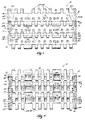
- Fig. 1 is a top plan view of a conveyor chain assembly according to the invention.
- Fig. 2 is a bottom plan view of the conveyor chain assembly shown in Fig. 1.
- Fig. 3 is an enlarged end view of a portion of the conveyor chain assembly shown in Fig. 1 and including an end of a chain module with an arm of a plug in a chain pin blocking position.
- Fig. 4 is a view taken along line 4-4 in Fig. 3 and with portions broken away for purposes of illustration.
- Fig. 5 is a view similar to Fig. 3 showing the arm of the plug in a first position.
- Fig. 6 is a partial side view taken along line 6-6 in Fig. 3.
- Fig. 7 is a view taken along line 7-7 in Fig. 5 and with portions broken away for purposes of illustration.
- Fig. 8 is a perspective view of the plug.
- a conveyor chain assembly 10 is illustrated in Figs. 1 and 2 and includes a multiplicity of rows of intermeshed chain modules 12 of which only three are depicted in Figs. 1 and 2. While in the illustrated construction the rows of modules are made up of only a single module, the rows of modules could include more than one module to form a wider conveyor chain.
- Each module 12 may be comprised of molded plastic and includes opposite ends 16 and 18, an intermediate section 20 and a longitudinal axis 22.
- a plurality of link ends 24 project forwardly and rearwardly from the intermediate section 20 with respect to the direction of movement of the conveyor chain 10.
- a first set 26 of link ends 24 projects forwardly of the intermediate section 20 and a second set 28 of link ends 24 projects rearwardly of the intermediate section 20.
- the intermediate section 20 thus integrally joins the first set 26 and the second set 28 of link ends 24.
- the link ends 24 include therethrough coaxially aligned openings or bores 30.
- Either the first set 26 or the second set 28 of link ends 24 includes a special type of link end or terminating link end 32 which forms each end 16 and 18 of the module 12.
- the terminating link 32 end includes an outer portion 34, an inner portion 36 and an end wall 38 (Figs. 3 and 5).
- the coaxially aligned opening 30 of the terminating link end 32 has an outer part 40 and an inner part 42.
- the outer part is defined by an annular wall 44 (Figs. 4 and 7).
- each module 12 intermesh with the link ends 24 of a module 12 in an adjacent row to form the conveyor chain.
- the modules 12 are interconnected in this intermeshed position by a pivot, hinge or chain pin 46 running through the coaxially aligned openings 30 of the intermeshed link ends 24 of adjacent modules 12.
- the chain pin 46 has a longitudinal axis 48 (Fig. 4) and two ends 50, 52.
- the module 12 further includes a socket 54 on each end 16 and 18 of the module 12. More specifically, the socket 54 is defined by the intermediate section 20 and the terminating link end 32.
- the socket 54 includes a shaft cavity 56 that is parallel to the direction of the coaxially aligned openings 30 and parallel to the axis 22 of the module 12.
- the shaft cavity 56 has a longitudinal axis 58 and is spaced from the coaxially aligned openings 30.
- the shaft cavity 56 includes a first inlet 60, a second inlet 62 (Fig. 4), a head portion 64, and a leg portion 66.
- a wall 68 separates the head portion 64 from the leg portion 66.
- the wall 68 has an outer and an inner surface 70 and 72 respectively and has an aperture 74 therethrough. The aperture 74 allows communication between the head portion 64 and the leg portions 66.
- the socket 54 further includes an arm cavity 76 having an inlet 78 (Fig. 4).
- the arm cavity 76 is transverse to the direction of the coaxially aligned openings 30 and transverse to the axis 22 of the module 12.
- the arm cavity 76 communicates with the shaft cavity 56.
- the arm cavity 76 separates the terminating link end 32 into the outer portion 34 with the outer part 40 of the opening 30 and the inner portion 36 with the inner part 42 of the opening 30.
- the arm cavity 76 communicates with both the outer and inner parts 40 and 42 of the opening 30.
- a chain pin retaining plug 80 is mountable in the module 12 for selectively restricting axial movement of the chain pin 46.
- the plug 80 includes a first portion or shaft 82 that is mountable in the shaft cavity 56 of the socket 54.
- the shaft 82 includes a shank 84 with a circular head 86 extending therefrom.
- the head 86 has a top surface 88 having therein a slot 90.
- the shaft 82 further includes means for securing the plug 80 in the socket 54 in the form of a pair of spaced legs 92 extending from the shank 84 in a direction opposite to that of the head 86.
- the legs are resilient such that the legs 92 can be deflected.
- Each leg 92 is tapered to facilitate insertion into the module 12 and each leg 92 terminates in a shoulder 94.
- the plug 80 further includes a second portion or arm 96 that is selectively housed in the arm cavity 76 of the socket 54 and moveable between a first position wherein the arm 96 does not restrict axial movement of the chain pin 46 (Fig. 5) and a second position wherein the arm 96 does restrict axial movement of the chain pin 46 (Fig. 4).
- the arm 96 is integral with and extends outwardly from the shank 84.
- a projection 98 extends from the arm 96 in the same direction the head 86 extends from shank 84. As shown in Fig. 8, the projection 98 has a top surface 100, a pair of linear edges 102 and 104 and a pair of curved edges 106 and 108.
- the top surface 100 has a pair of chamfered portions 110 and 112 that are adjacent the curved edges 106 and 108 and a rectangular portion 114 between the chamfered portions 110 and 112.
- the projection 98 comprises a means for releasably positioning the arm 96 in the arm cavity 76.
- the plug 80 is insertable into the module 12 as follows with reference to Figs. 4, 5, and 7. With resilient legs 92 first, the shaft 82 is moved in the shaft cavity 56 via the first inlet 60 in a direction parallel to the axis 48 of the chain pin 46. As the plug 80 is moved further into the shaft cavity 56, the resilient legs 92 contact the outer surface 70 of the wall 68 and must deform inwardly to enable the shoulders 94 to slide through the aperture 74. After the shoulders 94 have passed through the aperture 74 and into the leg portion 66 of the shaft cavity 56, the legs 92 resume their original orientation and spring outwardly.
- This first snap-fit is intended to be permanent in that the plug 80 is not designed to be removed from the module 12 after placing it in this position. Further, in this position, the head 86 is flush with the end 16 of the module 12, and the shank 84 contacts the outer surface 70 of the wall 68 to prohibit the plug 80 from moving further into the interior of the module 12. As shown in phantom in Fig.
- the arm 96 is in its first position filling the second inlet 62 of the shaft cavity 56 and not restricting the axial movement of the chain pin 46 such that the chain pin 46 can be inserted or removed from the aligned opening 30 in the link ends 24 without interference from the plug 80.
- the arm 96 When axial movement of the chain pin 46 needs to be restricted, such as when the conveyor is in operation, the arm 96 is moved into the second position as follows. Referring to Fig. 5, a tool such as a slotted screw driver is inserted into the slot 90 of the head 86 and rotated to enable the plug 80 to be pivoted about the axis 58 of the shaft cavity 56.
- the plug 80 is rotatable in only one direction because the end wall 38 of the terminating link end 32 prohibits rotation of the plug 80 in the other direction.
- the arm 96 While the plug 80 is being pivoted in the socket 54, the arm 96 enters the arm cavity 76 through the inlet 78 and the rectangular portion 114 of the top surface 100 of the projection 98 contacts the outer portion 34 of the terminating link end 32 causing the outer portion 34 to deform outwardly. This outward deformation allows the arm 96 to pass further into the arm cavity 76 until the projection 98 is clear of the outer portion 34 and the outer portion 34 returns to its normal orientation thus providing a second snap-fit as shown in Fig. 4. In this second position as shown in Figs. 3, 4, and 6, the arm 96 is fully inserted into the arm cavity 76 with no part thereof projecting outwardly from the module 12. The arm 96 occludes communication between the outer and inner parts 40 and 42 of the opening 30.
- the projection 98 extends into the outer part 40 of the opening 30 such that the curved edges 106 and 108 of the projection 98 contact the annular wall 44 and restrict pivotal movement of the arm 96 out of the arm cavity 76.
- the arm 96 restricts axial movement of one end 50 of the chain pin 46.
- a second plug 80 in this position on the other end 18 of the module 12 would restrict axial movement of the other end 52 of the chain pin 46. If the rows of the conveyor chain assembly include more than one module 12, a plug 80 is inserted only into the socket of the modules 12 that form the ends of the rows. Thus, only two plugs 80 are utilized per row for either row configuration.
- the second snap-fit is not intended to be permanent in that it is disengagable. If access or removal of the chain pin 46 is desired, the plug 80 is not removed from the module 12 but rather pivoted so that the arm 96 returns to the first position as hereafter described.
- the slotted screw driver is placed into the slot 90 of the head 86 and rotated to pivot the plug 80.
- the chamfered portion 112 of the projection 98 causes the outer portion 34 to deform outwardly enabling the arm 96 to clear the outer portion 34 of the terminating link end 32 and return to the first position in which the plug 80 does not restrict the axial movement of the chain pin 46.
- the plug 80 is inserted into and secured in the shaft cavity 56, it is not designed to be removable from the module 12. However, even though the plug 80 is not removable from the module 12, the chain pin 46 can still be removed or alternatively its movement restricted.
- the invention allows access to each chain pin 46 from either end of the row via the plug 80.
- the plug 80 is restricting axial movement of the chain pin 46, the plug 80 is more securely positioned in the module 12 because of the two snap-fits which reduce the chances of the plug 80 popping out of the module 12.
- the arm 96 provides additional load carrying capacity to the plug 80. In the ideal operation of the conveyor chain assembly 10, the arm 96 is not required to assume much load.
- the plug 80 does not project outwardly of the module 12 because the arm 96 is in the arm cavity 76 and the head 86 is flush with the end 16 of the module 12. This positioning of the plug 80 does not alter the top of the conveyor chain assembly 10 and allows independent conveyor chains to run next to each other at equal or different speeds without the need for guides and without the fear of jamming. Running multiple conveyor chains very close together provides improved product handling and transfer of products on and off the conveyor chains.
Abstract

Description
- This invention relates to conveyor chain assemblies which are made up of a multiplicity of pivotally interconnected chain modules.
- Some prior art conveyor chains are comprised of rows of molded plastic chain modules pivotally joined together by chain pins. Each module of such chains has a plurality of spaced link ends which intermesh with the complementary link ends projecting from a module in an adjacent row. Further, each link end has therein a bore which is coaxially aligned with the bores of other link ends to house the chain pin. In some arrangements, the chain pin projects from each edge or side of the conveyor chain and is provided with a head on one end of the chain pin to restrict axial movement of the chain pin. The head can be preformed but, in most cases, the head is formed by heat and pressure after the chain pin has been placed in position in the module. The head also projects from the side of the conveyor and can catch or drag on adjacent structures thus requiring additional lateral clearance between the conveyor and the conveyor guide or between adjacent conveyor chains. To remove the chain pin from an assembled chain, the head on one end of the chain pin has to be cut off. Once the head is severed, the chain pin becomes unusable because its length is too short to form a new head.
- Other prior art conveyor chains include plugs housed in the opposite ends of the link end bores to restrict axial movement of the chain pins. The plugs of such chains are normally small parts that can be lost or dropped on the floor of a production facility when they are inserted or removed from the modules. In some prior art constructions, these plugs have a tendency to be dislodged or pop out of the module when the conveyor chain is in use. Without the plug restricting axial movement of chain pin, the chain pins can become dislodged from their proper position and cause a disruption in the conveyor assembly.
- The invention provides a conveyor chain assembly including a multiplicity of rows of chain modules. Each module includes an intermediate section, a plurality of link ends projecting forwardly and rearwardly from the intermediate section with respect to the direction of movement of the conveyor chain. The link ends of each chain module intermesh with the link ends of the chain module in the adjacent row. A chain pin passes through aligned bores provided in the intermeshing link ends between the rows. The module at each end of the row of modules includes a plug socket which houses a plug. The plug includes a first portion mounted in the socket and a second portion which is moveable when the first portion is mounted in the socket. The second portion is moveable between a first position in which the second portion restricts axial movement of the chain pin and a second position in which the second portion does not restrict axial movement of the chain pin.
- One feature of the invention is to provide a conveyor chain assembly in which the chain pin can be accessed or removed from the module without damaging the chain pin and without damaging or removing the plug. The plug remains in the module after initial insertion so that the plug cannot be lost or dropped. The plug is moveable in the module with a hand tool between a position which restricts axial movement of the chain pin and a position which does not restrict axial movement of the chain pin.
- A further feature of the invention is that the plug is securable in the module in two separate locations which reduces the possibility the plug will pop out of the module.
- A further feature of the invention is that the axial forces on the chain pin cause the chain pin to engage the plug in such a manner as to secure the plug in the module even more thus reducing the possibility the plug will pop out of the module. The plug also distributes the axial forces on the chain pin to the module. The plug can thus operate under greater adversities while providing a greater level of reliability to the user.
- The invention is not limited to the details of construction and the arrangement of components set forth in the following description or illustrated in the drawings. The invention is capable of other embodiments and of being practiced and carried out in various ways. Also, it is to be understood that the phraseology and terminology employed herein is for the purpose of description and should not be regarded as limiting.
- Fig. 1 is a top plan view of a conveyor chain assembly according to the invention.
- Fig. 2 is a bottom plan view of the conveyor chain assembly shown in Fig. 1.
- Fig. 3 is an enlarged end view of a portion of the conveyor chain assembly shown in Fig. 1 and including an end of a chain module with an arm of a plug in a chain pin blocking position.
- Fig. 4 is a view taken along line 4-4 in Fig. 3 and with portions broken away for purposes of illustration.
- Fig. 5 is a view similar to Fig. 3 showing the arm of the plug in a first position.
- Fig. 6 is a partial side view taken along line 6-6 in Fig. 3.
- Fig. 7 is a view taken along line 7-7 in Fig. 5 and with portions broken away for purposes of illustration.
- Fig. 8 is a perspective view of the plug.
- Referring to the drawings, a
conveyor chain assembly 10 is illustrated in Figs. 1 and 2 and includes a multiplicity of rows of intermeshedchain modules 12 of which only three are depicted in Figs. 1 and 2. While in the illustrated construction the rows of modules are made up of only a single module, the rows of modules could include more than one module to form a wider conveyor chain. Eachmodule 12 may be comprised of molded plastic and includesopposite ends 16 and 18, anintermediate section 20 and alongitudinal axis 22. A plurality of link ends 24 project forwardly and rearwardly from theintermediate section 20 with respect to the direction of movement of theconveyor chain 10. A first set 26 of link ends 24 projects forwardly of theintermediate section 20 and a second set 28 of link ends 24 projects rearwardly of theintermediate section 20. Theintermediate section 20 thus integrally joins the first set 26 and the second set 28 of link ends 24. The link ends 24 include therethrough coaxially aligned openings or bores 30. - Either the first set 26 or the second set 28 of link ends 24 includes a special type of link end or terminating
link end 32 which forms eachend 16 and 18 of themodule 12. The terminatinglink 32 end includes anouter portion 34, aninner portion 36 and an end wall 38 (Figs. 3 and 5). The coaxially aligned opening 30 of the terminatinglink end 32 has anouter part 40 and aninner part 42. The outer part is defined by an annular wall 44 (Figs. 4 and 7). - The link ends 24 of each
module 12 intermesh with the link ends 24 of amodule 12 in an adjacent row to form the conveyor chain. Themodules 12 are interconnected in this intermeshed position by a pivot, hinge orchain pin 46 running through the coaxially aligned openings 30 of the intermeshed link ends 24 ofadjacent modules 12. Thechain pin 46 has a longitudinal axis 48 (Fig. 4) and twoends - Continuing to refer to Figs. 1 and 2, the
module 12 further includes a socket 54 on eachend 16 and 18 of themodule 12. More specifically, the socket 54 is defined by theintermediate section 20 and the terminatinglink end 32. The socket 54 includes a shaft cavity 56 that is parallel to the direction of the coaxially aligned openings 30 and parallel to theaxis 22 of themodule 12. The shaft cavity 56 has a longitudinal axis 58 and is spaced from the coaxially aligned openings 30. The shaft cavity 56 includes afirst inlet 60, a second inlet 62 (Fig. 4), ahead portion 64, and aleg portion 66. Awall 68 separates thehead portion 64 from theleg portion 66. Thewall 68 has an outer and aninner surface aperture 74 therethrough. Theaperture 74 allows communication between thehead portion 64 and theleg portions 66. - The socket 54 further includes an
arm cavity 76 having an inlet 78 (Fig. 4). Thearm cavity 76 is transverse to the direction of the coaxially aligned openings 30 and transverse to theaxis 22 of themodule 12. Thearm cavity 76 communicates with the shaft cavity 56. Thearm cavity 76 separates the terminatinglink end 32 into theouter portion 34 with theouter part 40 of the opening 30 and theinner portion 36 with theinner part 42 of the opening 30. Thearm cavity 76 communicates with both the outer andinner parts - As shown in Figs. 4 and 8, a chain
pin retaining plug 80 is mountable in themodule 12 for selectively restricting axial movement of thechain pin 46. Theplug 80 includes a first portion orshaft 82 that is mountable in the shaft cavity 56 of the socket 54. Theshaft 82 includes ashank 84 with acircular head 86 extending therefrom. Thehead 86 has atop surface 88 having therein aslot 90. Theshaft 82 further includes means for securing theplug 80 in the socket 54 in the form of a pair of spacedlegs 92 extending from theshank 84 in a direction opposite to that of thehead 86. The legs are resilient such that thelegs 92 can be deflected. Eachleg 92 is tapered to facilitate insertion into themodule 12 and eachleg 92 terminates in ashoulder 94. - Continuing to refer to Figs. 4 and 8, the
plug 80 further includes a second portion orarm 96 that is selectively housed in thearm cavity 76 of the socket 54 and moveable between a first position wherein thearm 96 does not restrict axial movement of the chain pin 46 (Fig. 5) and a second position wherein thearm 96 does restrict axial movement of the chain pin 46 (Fig. 4). Thearm 96 is integral with and extends outwardly from theshank 84. Aprojection 98 extends from thearm 96 in the same direction thehead 86 extends fromshank 84. As shown in Fig. 8, theprojection 98 has atop surface 100, a pair oflinear edges curved edges top surface 100 has a pair ofchamfered portions curved edges rectangular portion 114 between thechamfered portions projection 98 comprises a means for releasably positioning thearm 96 in thearm cavity 76. - The
plug 80 is insertable into themodule 12 as follows with reference to Figs. 4, 5, and 7. Withresilient legs 92 first, theshaft 82 is moved in the shaft cavity 56 via thefirst inlet 60 in a direction parallel to theaxis 48 of thechain pin 46. As theplug 80 is moved further into the shaft cavity 56, theresilient legs 92 contact theouter surface 70 of thewall 68 and must deform inwardly to enable theshoulders 94 to slide through theaperture 74. After theshoulders 94 have passed through theaperture 74 and into theleg portion 66 of the shaft cavity 56, thelegs 92 resume their original orientation and spring outwardly. In this position, theshoulders 94 contact theinner surface 72 of thewall 68 and thewall 68 does not allow theshoulders 92 to pass back through theaperture 74 thus retaining theplug 80 in the socket 54 and providing a snap-fit. This first snap-fit is intended to be permanent in that theplug 80 is not designed to be removed from themodule 12 after placing it in this position. Further, in this position, thehead 86 is flush with theend 16 of themodule 12, and theshank 84 contacts theouter surface 70 of thewall 68 to prohibit theplug 80 from moving further into the interior of themodule 12. As shown in phantom in Fig. 5, thearm 96 is in its first position filling the second inlet 62 of the shaft cavity 56 and not restricting the axial movement of thechain pin 46 such that thechain pin 46 can be inserted or removed from the aligned opening 30 in the link ends 24 without interference from theplug 80. - When axial movement of the
chain pin 46 needs to be restricted, such as when the conveyor is in operation, thearm 96 is moved into the second position as follows. Referring to Fig. 5, a tool such as a slotted screw driver is inserted into theslot 90 of thehead 86 and rotated to enable theplug 80 to be pivoted about the axis 58 of the shaft cavity 56. Theplug 80 is rotatable in only one direction because theend wall 38 of the terminatinglink end 32 prohibits rotation of theplug 80 in the other direction. While theplug 80 is being pivoted in the socket 54, thearm 96 enters thearm cavity 76 through theinlet 78 and therectangular portion 114 of thetop surface 100 of theprojection 98 contacts theouter portion 34 of the terminatinglink end 32 causing theouter portion 34 to deform outwardly. This outward deformation allows thearm 96 to pass further into thearm cavity 76 until theprojection 98 is clear of theouter portion 34 and theouter portion 34 returns to its normal orientation thus providing a second snap-fit as shown in Fig. 4. In this second position as shown in Figs. 3, 4, and 6, thearm 96 is fully inserted into thearm cavity 76 with no part thereof projecting outwardly from themodule 12. Thearm 96 occludes communication between the outer andinner parts projection 98 extends into theouter part 40 of the opening 30 such that thecurved edges projection 98 contact theannular wall 44 and restrict pivotal movement of thearm 96 out of thearm cavity 76. In this second position, thearm 96 restricts axial movement of oneend 50 of thechain pin 46. As shown in Figs. 1 and 2, asecond plug 80 in this position on the other end 18 of themodule 12 would restrict axial movement of theother end 52 of thechain pin 46. If the rows of the conveyor chain assembly include more than onemodule 12, aplug 80 is inserted only into the socket of themodules 12 that form the ends of the rows. Thus, only twoplugs 80 are utilized per row for either row configuration. - The second snap-fit is not intended to be permanent in that it is disengagable. If access or removal of the
chain pin 46 is desired, theplug 80 is not removed from themodule 12 but rather pivoted so that thearm 96 returns to the first position as hereafter described. The slotted screw driver is placed into theslot 90 of thehead 86 and rotated to pivot theplug 80. As theplug 80 is pivoted, the chamferedportion 112 of theprojection 98 causes theouter portion 34 to deform outwardly enabling thearm 96 to clear theouter portion 34 of the terminatinglink end 32 and return to the first position in which theplug 80 does not restrict the axial movement of thechain pin 46. - Once the
plug 80 is inserted into and secured in the shaft cavity 56, it is not designed to be removable from themodule 12. However, even though theplug 80 is not removable from themodule 12, thechain pin 46 can still be removed or alternatively its movement restricted. The invention allows access to eachchain pin 46 from either end of the row via theplug 80. When theplug 80 is restricting axial movement of thechain pin 46, theplug 80 is more securely positioned in themodule 12 because of the two snap-fits which reduce the chances of theplug 80 popping out of themodule 12. More specifically, thearm 96 provides additional load carrying capacity to theplug 80. In the ideal operation of theconveyor chain assembly 10, thearm 96 is not required to assume much load. However, when a product is channeled to one side of theconveyor chain assembly 10 or theconveyor chain assembly 10 is misaligned, an uneven load distribution in the link ends 24 results. This uneven load can be transmitted to thechain pin 46 causing an axial component of the uneven load to force thechain pin 46 out to one side of themodule 12. Because thearm 96 is perpendicular to theaxis 48 of thechain pin 46, these axial forces of thechain pin 46 cause the pin to engage thearm 96 in such a manner as to lock theplug 80, and more specifically theprojection 98 of thearm 96, in place all the more as well as distribute the axial load of thechain pin 46 onto the terminating link ends 32. This transfer of forces causes theplug 80 to work under greater adversities while providing a greater level of reliability to the user. - Further, the
plug 80 does not project outwardly of themodule 12 because thearm 96 is in thearm cavity 76 and thehead 86 is flush with theend 16 of themodule 12. This positioning of theplug 80 does not alter the top of theconveyor chain assembly 10 and allows independent conveyor chains to run next to each other at equal or different speeds without the need for guides and without the fear of jamming. Running multiple conveyor chains very close together provides improved product handling and transfer of products on and off the conveyor chains.
Claims (33)
- An apparatus for use in forming a conveyor chain, said apparatus comprising:
a module including a first set of link ends projecting forwardly of said module and a second set of link end projects rearwardly of said module with respect to the direction of movement of the conveyor chain, an intermediate section integrally joining said first and second set of link ends, said module including opposite ends, at least some of said link ends including coaxially aligned openings adapted to receive a chain pin having a longitudinal axis, and at least one of said opposite ends including a socket; and
a chain pin retaining plug including a first portion mounted in said socket and a second portion which is moveable when said first portion is housed in said socket between a first position wherein said second portion does not restrict axial movement of the chain pin and a second position wherein said second portion does restrict axial movement of the chain pin. - An apparatus as set forth in claim 1 wherein said first portion of said plug pivots in said socket when said second portion moves between said first position and said second position.
- An apparatus as set forth in claim 2 wherein said first portion is insertable into said socket in a direction parallel to the longitudinal axis of the chain pin.
- An apparatus as set forth in claim 3 wherein said first portion includes a shaft and said second portion includes an arm projecting outwardly from said shaft and wherein said arm occludes one of said coaxially aligned openings in said link ends when said arm is in said second position.
- An apparatus as set forth in claim 4 wherein said socket includes a shaft cavity adapted to house said shaft, and an arm cavity adapted to house said arm when said arm is in said second position.
- An apparatus as set forth in claim 5 wherein said shaft cavity is spaced from said coaxially aligned openings.
- An apparatus as set forth in claim 5 wherein said module has a longitudinal axis and wherein said shaft cavity is parallel to said longitudinal axis of said module and said arm cavity is transverse to said longitudinal axis of said module.
- An apparatus as set forth in claim 1 and further including means for securing said plug in said socket.
- An apparatus as set forth in claim 8 wherein said securing means includes at least one resilient leg on said plug.
- An apparatus as set forth in claim 4 wherein said shaft has opposite ends, one of said opposite ends includes at least one resilient leg and the other of said opposite ends includes a head.
- An apparatus as set forth in claim 10 wherein said head is positioned in said socket such that said head is flush with one of said opposite ends of said module.
- An apparatus as set forth in claim 5 further comprising means for releasably positioning said arm in said arm cavity.
- An apparatus as set forth in claim 12 wherein said positioning means includes a projection on said arm.
- An apparatus for use in forming a conveyor chain, said apparatus comprising:
a module including a plurality of link ends projecting outwardly from said module, at least some of said link ends including coaxially aligned openings adapted to receive a chain pin having a longitudinal axis, and a socket; and
a plug mountable in said socket, said plug when mounted in said socket being supported for movement between a first position not restricting axial movement of the chain pin and a second position restricting axial movement of the chain pin. - An apparatus as set forth in claim 14 wherein said plurality of link ends includes a first set of link ends projecting forwardly of said module and a second set of link end projecting rearwardly of said module with respect to the direction of movement of the conveyor chain.
- An apparatus as set forth in claim 14 wherein said plug is pivotable in said socket between said first position and said second position.
- An apparatus as set forth in claim 14 wherein said plug is insertable into said socket in a direction parallel to said longitudinal axis of the chain pin.
- An apparatus as set forth in claim 14 wherein said plug includes a shaft and an arm projecting outwardly from said shaft and wherein said arm occludes one of said coaxially aligned openings when said arm in said second position.
- An apparatus as set forth in claim 18 wherein said socket comprises a shaft cavity adapted to house said shaft and an arm cavity adapted to house said arm.
- An apparatus as set forth in claim 19 wherein said shaft cavity is spaced from said coaxially aligned openings.
- An apparatus as set forth in claim 19 wherein said module has a longitudinal axis and wherein said shaft cavity is parallel to said longitudinal axis of said module and said arm cavity is transverse to said longitudinal axis of said module.
- An apparatus as set forth in claim 14 and further including means for securing said plug in said socket.
- An apparatus as set forth in claim 22 wherein said securing means includes at least one resilient leg on said plug.
- An apparatus as set forth in claim 18 wherein said shaft has opposite ends, one of said opposite ends includes at least one resilient leg and the other of said opposite ends includes a head.
- An apparatus as set forth in claim 24 wherein said module has an end surface and wherein said plug is mounted in said socket such that said head is flush with said end surface.
- An apparatus as set forth in claim 19 further comprising means for releasably positioning said arm in said arm cavity.
- An apparatus as set forth in claim 26 wherein said positioning means includes a projection on said arm.
- A plug for use with a chain module having a socket and being adapted to receive a chain pin, said plug comprising:
a first portion including a shaft having a longitudinal axis, the first portion being insertable into the socket in the direction of the longitudinal axis; and
a second portion integral with the said first portion and projecting from the first portion in a direction transverse to the longitudinal axis, said second portion being moveable when said first portion is housed in the socket between a first position wherein said second portion does not restrict axial movement of the chain pin and a second position wherein said second portion does restrict axial movement of the chain pin. - A plug as set forth in claim 28 wherein said second portion comprises an arm projecting outwardly from said shaft.
- A plug as set forth in claim 28 wherein said plug further includes means for securing said plug in the socket.
- A plug as set forth in claim 31 wherein said securing means includes at least one resilient leg on said first portion.
- A plug as set forth in claim 31 wherein said plug further includes means for removeably positioning said second portion in said second position.
- A conveyor chain assembly comprising:
a multiplicity of rows of chain modules, each of said modules having opposite ends and a plurality of link ends projecting forwardly and rearwardly from said modules with respect to the direction of movement of the conveyor chain assembly, said link ends of one module intermesh with said link ends of another module in an adjacent row, and said opposite ends including a plug socket;
a pivot pin passing through said intermeshing link ends between said rows; and
a plug including a first portion mounted in said socket and a second portion which is moveable when said first portion is mounted in said socket between a first position wherein said second portion does not restrict axial movement of said pivot pin and a second position wherein said second portion does restrict axial movement of said pivot pin.
Applications Claiming Priority (2)
| Application Number | Priority Date | Filing Date | Title |
|---|---|---|---|
| US30621 | 1993-03-12 | ||
| US08/030,621 US5335768A (en) | 1993-03-12 | 1993-03-12 | Conveyor chain assembly |
Publications (2)
| Publication Number | Publication Date |
|---|---|
| EP0620169A1 true EP0620169A1 (en) | 1994-10-19 |
| EP0620169B1 EP0620169B1 (en) | 1998-07-08 |
Family
ID=21855103
Family Applications (1)
| Application Number | Title | Priority Date | Filing Date |
|---|---|---|---|
| EP94100878A Expired - Lifetime EP0620169B1 (en) | 1993-03-12 | 1994-01-21 | Conveyor chain assembly |
Country Status (9)
| Country | Link |
|---|---|
| US (1) | US5335768A (en) |
| EP (1) | EP0620169B1 (en) |
| JP (1) | JP3344803B2 (en) |
| KR (1) | KR100294356B1 (en) |
| AU (1) | AU668617B2 (en) |
| CA (1) | CA2111037C (en) |
| DE (1) | DE69411434T2 (en) |
| DK (1) | DK0620169T3 (en) |
| ES (1) | ES2118985T3 (en) |
Cited By (1)
| Publication number | Priority date | Publication date | Assignee | Title |
|---|---|---|---|---|
| NL2005773C2 (en) * | 2010-11-29 | 2012-05-30 | Kaak Johan Bernard | SCHALMENBAND. |
Families Citing this family (51)
| Publication number | Priority date | Publication date | Assignee | Title |
|---|---|---|---|---|
| US5634550A (en) * | 1993-03-12 | 1997-06-03 | Rexnord Corporation | Direction changing mechanism for transferring articles between transverse conveyors |
| JP2551150Y2 (en) * | 1993-07-13 | 1997-10-22 | 株式会社椿本チエイン | Conveyor belt that can be expanded and widened |
| DK125793A (en) * | 1993-11-05 | 1995-05-06 | Baeltix Maskinfabrikken As | Chain link with locking strap for conveyor chains and conveyor belts |
| IT1276058B1 (en) * | 1994-11-08 | 1997-10-24 | Regina Sud Spa | IMPROVED CHAIN CONVEYOR, WITH IMPROVED STABILITY AND SLIDING CHARACTERISTICS |
| US5573106A (en) * | 1996-02-05 | 1996-11-12 | Rexnord Corporation | Modular conveyor chain including headed hinge pins |
| US5662211A (en) * | 1996-02-05 | 1997-09-02 | Rexnord Corporation | Conveyor chain with self retaining hinge pin with internal barbs |
| US5678683A (en) * | 1996-02-05 | 1997-10-21 | Rexnord Corporation | Conveyor chain with sealed plug hinge pin retention system |
| NL1002501C2 (en) * | 1996-03-01 | 1997-09-03 | Mcc Nederland | Plastic module for a transport mat. |
| US6041917A (en) * | 1996-06-10 | 2000-03-28 | Span Tech Llc | Modular link conveyor with interdigitating grid and open apex |
| US5690210A (en) * | 1996-06-10 | 1997-11-25 | Span Tech Corporation | Modular link conveyor with interdigitating grid |
| US6223889B1 (en) | 1996-06-10 | 2001-05-01 | Span Tech Llc | Modular link conveyor with interdigitating grid and interleaving side wings |
| US5899322A (en) * | 1996-08-22 | 1999-05-04 | Regina-Emerson Company | Retention clip for conveyor belts |
| US5904241A (en) * | 1996-09-05 | 1999-05-18 | The Laitram Corporation | Shuttle plugs for retaining headless pivot rods in conveyor belts |
| USD420777S (en) * | 1996-11-07 | 2000-02-15 | Maskinfabrikken Baeltix A/S | Chain link module for a conveyor belt |
| US5960937A (en) * | 1997-10-27 | 1999-10-05 | Rexnord Corporation | Conveyor with hinge pin retention plug with snap fit |
| NL1008343C2 (en) * | 1998-02-18 | 1999-08-19 | Mcc Nederland | Module with retaining element for use in a modular transport mat. |
| JP2951316B1 (en) * | 1998-05-29 | 1999-09-20 | 株式会社椿本チエイン | Conveyor chain made of synthetic resin |
| JP3448220B2 (en) * | 1998-07-29 | 2003-09-22 | 株式会社椿本チエイン | Slat conveyor chain |
| US6345715B2 (en) * | 1998-11-03 | 2002-02-12 | Kvp Falcon Plastic Belting, Inc. | Rod retention system for modular plastic conveyor belt |
| DE19905111A1 (en) | 1999-02-09 | 2000-08-10 | Flexon Pirna Gmbh | Chain element for a conveyor chain, in particular for a mat conveyor chain |
| US6161685A (en) * | 1999-03-26 | 2000-12-19 | Rexnord Corporation | Thermoplastic chain link for a modular conveyor chain |
| IT246710Y1 (en) * | 1999-05-06 | 2002-04-09 | Regina Sud Spa | CHAIN CONVEYOR WITH CHANNEL GUIDE |
| US6499587B1 (en) | 2000-08-21 | 2002-12-31 | The Laitram Corporation | Plastic modules, conveyor belts and methods for assembling and disassembling pivotably connected plastic modules |
| ITMI20010599U1 (en) * | 2001-11-13 | 2003-05-13 | System Plast Spa | CHAIN CONVEYOR |
| US20060237290A1 (en) * | 2003-08-12 | 2006-10-26 | Dieter Guldenfels | Device for retaining a headed pivot rod |
| US6814223B1 (en) | 2003-09-25 | 2004-11-09 | Laitram, L.L.C. | Self-closing hinge rod retention in modular plastic conveyor belts |
| US6857516B1 (en) | 2003-11-05 | 2005-02-22 | Laitram, L.L.C. | Hinge rod retention clips in modular plastic conveyor belt edges |
| US8151978B2 (en) * | 2004-11-05 | 2012-04-10 | Rexnord Industries, Llc | Low backline pressure modular conveying assembly |
| US7255227B2 (en) * | 2005-04-04 | 2007-08-14 | Laitram, L.L.C. | Hinge rod retention in modular conveyor belt edges by means of resilient blocking elements |
| US7494005B2 (en) * | 2005-09-30 | 2009-02-24 | Cambridge International, Inc. | Variable spaced conveyor belt |
| US9550628B2 (en) * | 2007-12-27 | 2017-01-24 | Laitram, L.L.C. | Module for a modular conveyor belt |
| ATE543760T1 (en) * | 2008-02-01 | 2012-02-15 | System Plast S R L | CONVEYOR BELT WITH SEVERAL HINGE MODULES AND MEANS FOR AVOIDING AXIAL DISPLACEMENT OF THE MODULE PIGS |
| IT1392181B1 (en) * | 2008-12-11 | 2012-02-22 | System Plast S R L | CONVOGLIATORE |
| US20120018281A1 (en) * | 2010-07-21 | 2012-01-26 | Mccormick Stephen A | Conveyor belt with articulating transport surface |
| CN104093647B (en) * | 2011-12-06 | 2017-10-31 | 亚西渥斯兄弟公司 | The conveyer belt chain link of feature structure is kept with bar |
| US8720676B2 (en) | 2011-12-06 | 2014-05-13 | Ashworth Bros., Inc. | Conveyor belt link with rod retaining feature |
| US8636141B2 (en) | 2011-12-06 | 2014-01-28 | Ashworth Bros., Inc. | Conveyor belt link with rod retaining feature |
| US8607967B2 (en) | 2011-12-06 | 2013-12-17 | Ashworth Bros., Inc. | Conveyor belt link with rod retaining feature |
| CN104995110B (en) | 2012-10-25 | 2017-08-01 | 雷勃电气美国公司 | Control the apparatus and method of the path wear of conveyer |
| US9085414B2 (en) * | 2012-11-29 | 2015-07-21 | Solus Industrial Innovations, Llc | Side-flexing conveyors |
| JP6127139B2 (en) * | 2013-06-28 | 2017-05-10 | 株式会社椿本チエイン | Conveyor belt and belt components |
| ES2697755T3 (en) * | 2013-09-30 | 2019-01-28 | Laitram Llc | Magnetic conveyor belt module |
| NL2012090C2 (en) * | 2014-01-15 | 2015-07-16 | Rexnord Flattop Europe Bv | MODULAR TRANSPORT MAT AND MODULE THEREFOR, AND CHAIN WHEEL AND TRANSPORT SYSTEM. |
| US9139370B1 (en) * | 2015-02-25 | 2015-09-22 | George W. Massey, Jr. | Conveyor system and a mechanical chain having a plurality of links |
| US10155625B1 (en) | 2015-09-01 | 2018-12-18 | Laitram, L.L.C. | Conveyor belts and modules with twist-lock accessories |
| CN111670152B (en) | 2018-01-30 | 2022-12-27 | 剑桥国际股份有限公司 | Splicing system for conveyor belt |
| CN109878983A (en) * | 2019-01-10 | 2019-06-14 | 南通拓新自动化设备科技有限公司 | A kind of anti-extension connection structure of modular plastic foraminous conveyer |
| EP3733565A1 (en) * | 2019-05-02 | 2020-11-04 | Habasit AG | Modular conveyor belt having alternating drive surfaces |
| EP3733564A1 (en) * | 2019-05-02 | 2020-11-04 | Habasit AG | Modular conveyor belt having fluid guiding structures |
| NL2025273B1 (en) * | 2020-04-03 | 2021-10-25 | Rexnord Flattop Europe Bv | Modular conveyor mat and module for it |
| JP2024514862A (en) * | 2021-04-21 | 2024-04-03 | レイトラム,エル.エル.シー. | Module with conveyor belt and sliding body |
Citations (4)
| Publication number | Priority date | Publication date | Assignee | Title |
|---|---|---|---|---|
| EP0288409A1 (en) * | 1987-04-15 | 1988-10-26 | Rexnord Corporation | Conveyor chain assembly |
| EP0459691A1 (en) * | 1990-05-21 | 1991-12-04 | Ucc Corporation | Modular conveyor belt |
| EP0503333A1 (en) * | 1991-03-08 | 1992-09-16 | Rexnord Corporation | Modular conveyor chain having open hinge pin construction |
| US5217110A (en) * | 1992-04-23 | 1993-06-08 | Cambridge Wire Cloth Company | Modular plastic turn belt conveyor system, module, belt and drive therefor |
Family Cites Families (20)
| Publication number | Priority date | Publication date | Assignee | Title |
|---|---|---|---|---|
| US811391A (en) * | 1903-05-14 | 1906-01-30 | William H Gates | Drive-chain. |
| US1046124A (en) * | 1911-03-13 | 1912-12-03 | John F Wagner | Drive-chain. |
| US2631465A (en) * | 1949-05-11 | 1953-03-17 | Cordis Nat | Demountable chain |
| US2951578A (en) * | 1959-02-11 | 1960-09-06 | Chain Belt Co | Rubber pad attachment for conveyor chain |
| US4006817A (en) * | 1972-07-07 | 1977-02-08 | Incom International Inc. | Conveyor chain |
| US4832187A (en) * | 1980-08-19 | 1989-05-23 | The Laitram Corporation | Modular center drive conveyor belt |
| US5024321A (en) * | 1980-08-19 | 1991-06-18 | Laitram Corporation | Modular center drive conveyor belt |
| US5123524A (en) * | 1980-08-19 | 1992-06-23 | The Laitram Corporation | Modular center drive conveyor belt |
| GB2089475A (en) * | 1980-12-12 | 1982-06-23 | Quality Inspection Services Lt | Rotary couplings |
| US4557374A (en) * | 1982-02-23 | 1985-12-10 | The Cambridge Wire Cloth Company | Modular conveyor belting with cam-slotted links for maintaining transverse distribution of tension while negotiating horizontal curves and for facilitating cleaning |
| DE3241632C2 (en) * | 1982-11-11 | 1986-09-25 | Draadindustrie Jonge Poerink B.V., Borne | Conveyor belt made of plastic links with inserted cross bars |
| US5020659A (en) * | 1987-04-15 | 1991-06-04 | Rexnord Corporation | Conveyor chain assembly |
| US4858753A (en) * | 1987-04-15 | 1989-08-22 | Rexnord Corporation | Conveyor chain assembly |
| DK159544C (en) * | 1988-04-21 | 1991-04-02 | Baeltix A S Maskinfabrikken | CHAIRLED WITH WELDING TAPES AND WELDING TAPES HERE |
| US4993544A (en) * | 1989-01-13 | 1991-02-19 | Cambridge Wire Cloth Company | Plastic modular conveyor belts and modules therefor |
| US4893710A (en) * | 1989-01-13 | 1990-01-16 | Cambridge Wire Cloth Company | Plastic modular conveyor belts and modules therefor |
| US4953693A (en) * | 1989-01-23 | 1990-09-04 | Span Tech Corporation | Modular link conveyor system |
| US5031757A (en) * | 1989-12-26 | 1991-07-16 | Span Tech Corporation | Modular link conveyor system with narrow chain |
| US5083660A (en) * | 1990-11-08 | 1992-01-28 | The Laitram Corporation | Removably retaining pivot rods in modular plastic belts |
| SE9004102D0 (en) * | 1990-12-21 | 1990-12-21 | Skf Specialty Product Ab | PLASTIC CHAIN AND INSTALLABLE LOADING LEATHER RESPECTIVE STEERING STEP |
-
1993
- 1993-03-12 US US08/030,621 patent/US5335768A/en not_active Expired - Lifetime
- 1993-12-09 CA CA002111037A patent/CA2111037C/en not_active Expired - Lifetime
- 1993-12-28 JP JP35496393A patent/JP3344803B2/en not_active Expired - Lifetime
-
1994
- 1994-01-11 AU AU53121/94A patent/AU668617B2/en not_active Expired
- 1994-01-21 DE DE69411434T patent/DE69411434T2/en not_active Expired - Lifetime
- 1994-01-21 ES ES94100878T patent/ES2118985T3/en not_active Expired - Lifetime
- 1994-01-21 EP EP94100878A patent/EP0620169B1/en not_active Expired - Lifetime
- 1994-01-21 DK DK94100878T patent/DK0620169T3/en active
- 1994-03-04 KR KR1019940004181A patent/KR100294356B1/en not_active IP Right Cessation
Patent Citations (4)
| Publication number | Priority date | Publication date | Assignee | Title |
|---|---|---|---|---|
| EP0288409A1 (en) * | 1987-04-15 | 1988-10-26 | Rexnord Corporation | Conveyor chain assembly |
| EP0459691A1 (en) * | 1990-05-21 | 1991-12-04 | Ucc Corporation | Modular conveyor belt |
| EP0503333A1 (en) * | 1991-03-08 | 1992-09-16 | Rexnord Corporation | Modular conveyor chain having open hinge pin construction |
| US5217110A (en) * | 1992-04-23 | 1993-06-08 | Cambridge Wire Cloth Company | Modular plastic turn belt conveyor system, module, belt and drive therefor |
Cited By (2)
| Publication number | Priority date | Publication date | Assignee | Title |
|---|---|---|---|---|
| NL2005773C2 (en) * | 2010-11-29 | 2012-05-30 | Kaak Johan Bernard | SCHALMENBAND. |
| WO2012074383A1 (en) * | 2010-11-29 | 2012-06-07 | Kaak, Johan Hendrik Bernard | Linked belt |
Also Published As
| Publication number | Publication date |
|---|---|
| ES2118985T3 (en) | 1998-10-01 |
| DE69411434D1 (en) | 1998-08-13 |
| KR940021385A (en) | 1994-10-17 |
| CA2111037C (en) | 2004-09-21 |
| AU5312194A (en) | 1994-09-15 |
| CA2111037A1 (en) | 1994-09-13 |
| KR100294356B1 (en) | 2001-10-24 |
| DE69411434T2 (en) | 1998-10-29 |
| DK0620169T3 (en) | 1999-04-19 |
| JP3344803B2 (en) | 2002-11-18 |
| JPH072330A (en) | 1995-01-06 |
| US5335768A (en) | 1994-08-09 |
| EP0620169B1 (en) | 1998-07-08 |
| AU668617B2 (en) | 1996-05-09 |
Similar Documents
| Publication | Publication Date | Title |
|---|---|---|
| US5335768A (en) | Conveyor chain assembly | |
| CA2153467C (en) | Direction changing mechanism for transferring articles between transverse conveyors | |
| US5904241A (en) | Shuttle plugs for retaining headless pivot rods in conveyor belts | |
| US5960937A (en) | Conveyor with hinge pin retention plug with snap fit | |
| US4858753A (en) | Conveyor chain assembly | |
| US6000550A (en) | Wafer carrier box hinge | |
| US7699160B2 (en) | Conveyor comprising a plurality of hinged modules and means for avoiding axial displacement of the module hinge pins | |
| US5058732A (en) | Apparatus to allow non-destructive removal of pivot rods in modular plastic conveyor belts | |
| EP0844415B2 (en) | Cable drag chain | |
| KR100537285B1 (en) | Module having a retaining member for use in a modular conveyor mat | |
| US5293989A (en) | Chain conveyor link provided with a pin-locking device | |
| US6247583B1 (en) | Conveyor chain for transporting articles | |
| JPH02209308A (en) | Conveyor belt module | |
| MXPA98008900A (en) | Conveyor band with adjustment retention plug through jump with go pin | |
| CA1304711C (en) | Apparatus and methods to allow non-destructive removal of pivot rods in modular plastic conveyor belts | |
| JPH02209307A (en) | Conveyor belt module |
Legal Events
| Date | Code | Title | Description |
|---|---|---|---|
| PUAI | Public reference made under article 153(3) epc to a published international application that has entered the european phase |
Free format text: ORIGINAL CODE: 0009012 |
|
| AK | Designated contracting states |
Kind code of ref document: A1 Designated state(s): DE DK ES FR GB IT SE |
|
| 17P | Request for examination filed |
Effective date: 19941223 |
|
| 17Q | First examination report despatched |
Effective date: 19960529 |
|
| GRAG | Despatch of communication of intention to grant |
Free format text: ORIGINAL CODE: EPIDOS AGRA |
|
| GRAG | Despatch of communication of intention to grant |
Free format text: ORIGINAL CODE: EPIDOS AGRA |
|
| GRAG | Despatch of communication of intention to grant |
Free format text: ORIGINAL CODE: EPIDOS AGRA |
|
| GRAH | Despatch of communication of intention to grant a patent |
Free format text: ORIGINAL CODE: EPIDOS IGRA |
|
| GRAH | Despatch of communication of intention to grant a patent |
Free format text: ORIGINAL CODE: EPIDOS IGRA |
|
| GRAA | (expected) grant |
Free format text: ORIGINAL CODE: 0009210 |
|
| ITF | It: translation for a ep patent filed |
Owner name: DE DOMINICIS & MAYER S.R.L. |
|
| AK | Designated contracting states |
Kind code of ref document: B1 Designated state(s): DE DK ES FR GB IT SE |
|
| REF | Corresponds to: |
Ref document number: 69411434 Country of ref document: DE Date of ref document: 19980813 |
|
| REG | Reference to a national code |
Ref country code: ES Ref legal event code: FG2A Ref document number: 2118985 Country of ref document: ES Kind code of ref document: T3 |
|
| ET | Fr: translation filed | ||
| REG | Reference to a national code |
Ref country code: DK Ref legal event code: T3 |
|
| PLBE | No opposition filed within time limit |
Free format text: ORIGINAL CODE: 0009261 |
|
| STAA | Information on the status of an ep patent application or granted ep patent |
Free format text: STATUS: NO OPPOSITION FILED WITHIN TIME LIMIT |
|
| 26N | No opposition filed | ||
| REG | Reference to a national code |
Ref country code: GB Ref legal event code: IF02 |
|
| PG25 | Lapsed in a contracting state [announced via postgrant information from national office to epo] |
Ref country code: IT Free format text: LAPSE BECAUSE OF NON-PAYMENT OF DUE FEES Effective date: 20080121 |
|
| PGFP | Annual fee paid to national office [announced via postgrant information from national office to epo] |
Ref country code: IT Payment date: 20120124 Year of fee payment: 19 |
|
| PGFP | Annual fee paid to national office [announced via postgrant information from national office to epo] |
Ref country code: FR Payment date: 20130211 Year of fee payment: 20 Ref country code: DK Payment date: 20130125 Year of fee payment: 20 Ref country code: ES Payment date: 20130128 Year of fee payment: 20 Ref country code: DE Payment date: 20130129 Year of fee payment: 20 Ref country code: SE Payment date: 20130129 Year of fee payment: 20 Ref country code: GB Payment date: 20130125 Year of fee payment: 20 |
|
| REG | Reference to a national code |
Ref country code: DE Ref legal event code: R071 Ref document number: 69411434 Country of ref document: DE |
|
| REG | Reference to a national code |
Ref country code: DK Ref legal event code: EUP Effective date: 20140121 |
|
| REG | Reference to a national code |
Ref country code: GB Ref legal event code: PE20 Expiry date: 20140120 |
|
| REG | Reference to a national code |
Ref country code: SE Ref legal event code: EUG |
|
| REG | Reference to a national code |
Ref country code: ES Ref legal event code: FD2A Effective date: 20140407 |
|
| PG25 | Lapsed in a contracting state [announced via postgrant information from national office to epo] |
Ref country code: DE Free format text: LAPSE BECAUSE OF EXPIRATION OF PROTECTION Effective date: 20140122 Ref country code: GB Free format text: LAPSE BECAUSE OF EXPIRATION OF PROTECTION Effective date: 20140120 |
|
| PG25 | Lapsed in a contracting state [announced via postgrant information from national office to epo] |
Ref country code: ES Free format text: LAPSE BECAUSE OF EXPIRATION OF PROTECTION Effective date: 20140122 |