EP0620152B1 - Vorrichtung zum Anbringen von Ausgiessern - Google Patents
Vorrichtung zum Anbringen von Ausgiessern Download PDFInfo
- Publication number
- EP0620152B1 EP0620152B1 EP94302511A EP94302511A EP0620152B1 EP 0620152 B1 EP0620152 B1 EP 0620152B1 EP 94302511 A EP94302511 A EP 94302511A EP 94302511 A EP94302511 A EP 94302511A EP 0620152 B1 EP0620152 B1 EP 0620152B1
- Authority
- EP
- European Patent Office
- Prior art keywords
- fitment
- holder
- wall
- container
- drive member
- Prior art date
- Legal status (The legal status is an assumption and is not a legal conclusion. Google has not performed a legal analysis and makes no representation as to the accuracy of the status listed.)
- Expired - Lifetime
Links
- 238000007789 sealing Methods 0.000 claims description 15
- 238000000034 method Methods 0.000 claims description 4
- 230000010355 oscillation Effects 0.000 claims description 3
- 230000003534 oscillatory effect Effects 0.000 claims description 3
- 238000011049 filling Methods 0.000 description 9
- 238000009740 moulding (composite fabrication) Methods 0.000 description 8
- 238000010276 construction Methods 0.000 description 1
- 230000009977 dual effect Effects 0.000 description 1
- 230000000694 effects Effects 0.000 description 1
- 239000000945 filler Substances 0.000 description 1
- 239000007788 liquid Substances 0.000 description 1
- 238000004519 manufacturing process Methods 0.000 description 1
- 238000003825 pressing Methods 0.000 description 1
- 230000000717 retained effect Effects 0.000 description 1
- 229920001169 thermoplastic Polymers 0.000 description 1
- 239000004416 thermosoftening plastic Substances 0.000 description 1
- 238000011144 upstream manufacturing Methods 0.000 description 1
- 238000003466 welding Methods 0.000 description 1
Images


Classifications
-
- B—PERFORMING OPERATIONS; TRANSPORTING
- B65—CONVEYING; PACKING; STORING; HANDLING THIN OR FILAMENTARY MATERIAL
- B65B—MACHINES, APPARATUS OR DEVICES FOR, OR METHODS OF, PACKAGING ARTICLES OR MATERIALS; UNPACKING
- B65B61/00—Auxiliary devices, not otherwise provided for, for operating on sheets, blanks, webs, binding material, containers or packages
- B65B61/18—Auxiliary devices, not otherwise provided for, for operating on sheets, blanks, webs, binding material, containers or packages for making package-opening or unpacking elements
- B65B61/186—Auxiliary devices, not otherwise provided for, for operating on sheets, blanks, webs, binding material, containers or packages for making package-opening or unpacking elements by applying or incorporating rigid fittings, e.g. discharge spouts
-
- B—PERFORMING OPERATIONS; TRANSPORTING
- B29—WORKING OF PLASTICS; WORKING OF SUBSTANCES IN A PLASTIC STATE IN GENERAL
- B29C—SHAPING OR JOINING OF PLASTICS; SHAPING OF MATERIAL IN A PLASTIC STATE, NOT OTHERWISE PROVIDED FOR; AFTER-TREATMENT OF THE SHAPED PRODUCTS, e.g. REPAIRING
- B29C65/00—Joining or sealing of preformed parts, e.g. welding of plastics materials; Apparatus therefor
- B29C65/02—Joining or sealing of preformed parts, e.g. welding of plastics materials; Apparatus therefor by heating, with or without pressure
- B29C65/08—Joining or sealing of preformed parts, e.g. welding of plastics materials; Apparatus therefor by heating, with or without pressure using ultrasonic vibrations
-
- B—PERFORMING OPERATIONS; TRANSPORTING
- B29—WORKING OF PLASTICS; WORKING OF SUBSTANCES IN A PLASTIC STATE IN GENERAL
- B29C—SHAPING OR JOINING OF PLASTICS; SHAPING OF MATERIAL IN A PLASTIC STATE, NOT OTHERWISE PROVIDED FOR; AFTER-TREATMENT OF THE SHAPED PRODUCTS, e.g. REPAIRING
- B29C66/00—General aspects of processes or apparatus for joining preformed parts
- B29C66/01—General aspects dealing with the joint area or with the area to be joined
- B29C66/05—Particular design of joint configurations
- B29C66/10—Particular design of joint configurations particular design of the joint cross-sections
- B29C66/11—Joint cross-sections comprising a single joint-segment, i.e. one of the parts to be joined comprising a single joint-segment in the joint cross-section
- B29C66/112—Single lapped joints
-
- B—PERFORMING OPERATIONS; TRANSPORTING
- B29—WORKING OF PLASTICS; WORKING OF SUBSTANCES IN A PLASTIC STATE IN GENERAL
- B29C—SHAPING OR JOINING OF PLASTICS; SHAPING OF MATERIAL IN A PLASTIC STATE, NOT OTHERWISE PROVIDED FOR; AFTER-TREATMENT OF THE SHAPED PRODUCTS, e.g. REPAIRING
- B29C66/00—General aspects of processes or apparatus for joining preformed parts
- B29C66/01—General aspects dealing with the joint area or with the area to be joined
- B29C66/05—Particular design of joint configurations
- B29C66/10—Particular design of joint configurations particular design of the joint cross-sections
- B29C66/13—Single flanged joints; Fin-type joints; Single hem joints; Edge joints; Interpenetrating fingered joints; Other specific particular designs of joint cross-sections not provided for in groups B29C66/11 - B29C66/12
- B29C66/131—Single flanged joints, i.e. one of the parts to be joined being rigid and flanged in the joint area
-
- B—PERFORMING OPERATIONS; TRANSPORTING
- B29—WORKING OF PLASTICS; WORKING OF SUBSTANCES IN A PLASTIC STATE IN GENERAL
- B29C—SHAPING OR JOINING OF PLASTICS; SHAPING OF MATERIAL IN A PLASTIC STATE, NOT OTHERWISE PROVIDED FOR; AFTER-TREATMENT OF THE SHAPED PRODUCTS, e.g. REPAIRING
- B29C66/00—General aspects of processes or apparatus for joining preformed parts
- B29C66/50—General aspects of joining tubular articles; General aspects of joining long products, i.e. bars or profiled elements; General aspects of joining single elements to tubular articles, hollow articles or bars; General aspects of joining several hollow-preforms to form hollow or tubular articles
- B29C66/51—Joining tubular articles, profiled elements or bars; Joining single elements to tubular articles, hollow articles or bars; Joining several hollow-preforms to form hollow or tubular articles
- B29C66/53—Joining single elements to tubular articles, hollow articles or bars
- B29C66/532—Joining single elements to the wall of tubular articles, hollow articles or bars
- B29C66/5324—Joining single elements to the wall of tubular articles, hollow articles or bars said single elements being substantially annular, i.e. of finite length
- B29C66/53245—Joining single elements to the wall of tubular articles, hollow articles or bars said single elements being substantially annular, i.e. of finite length said articles being hollow
- B29C66/53246—Joining single elements to the wall of tubular articles, hollow articles or bars said single elements being substantially annular, i.e. of finite length said articles being hollow said single elements being spouts, e.g. joining spouts to containers
- B29C66/53247—Joining single elements to the wall of tubular articles, hollow articles or bars said single elements being substantially annular, i.e. of finite length said articles being hollow said single elements being spouts, e.g. joining spouts to containers said spouts comprising flanges
-
- B—PERFORMING OPERATIONS; TRANSPORTING
- B29—WORKING OF PLASTICS; WORKING OF SUBSTANCES IN A PLASTIC STATE IN GENERAL
- B29C—SHAPING OR JOINING OF PLASTICS; SHAPING OF MATERIAL IN A PLASTIC STATE, NOT OTHERWISE PROVIDED FOR; AFTER-TREATMENT OF THE SHAPED PRODUCTS, e.g. REPAIRING
- B29C66/00—General aspects of processes or apparatus for joining preformed parts
- B29C66/50—General aspects of joining tubular articles; General aspects of joining long products, i.e. bars or profiled elements; General aspects of joining single elements to tubular articles, hollow articles or bars; General aspects of joining several hollow-preforms to form hollow or tubular articles
- B29C66/61—Joining from or joining on the inside
-
- B—PERFORMING OPERATIONS; TRANSPORTING
- B29—WORKING OF PLASTICS; WORKING OF SUBSTANCES IN A PLASTIC STATE IN GENERAL
- B29L—INDEXING SCHEME ASSOCIATED WITH SUBCLASS B29C, RELATING TO PARTICULAR ARTICLES
- B29L2031/00—Other particular articles
- B29L2031/712—Containers; Packaging elements or accessories, Packages
- B29L2031/7162—Boxes, cartons, cases
- B29L2031/7166—Cartons of the fruit juice or milk type, i.e. containers of polygonal cross sections formed by folding blanks into a tubular body with end-closing or contents-supporting elements, e.g. gable type containers
-
- B—PERFORMING OPERATIONS; TRANSPORTING
- B31—MAKING ARTICLES OF PAPER, CARDBOARD OR MATERIAL WORKED IN A MANNER ANALOGOUS TO PAPER; WORKING PAPER, CARDBOARD OR MATERIAL WORKED IN A MANNER ANALOGOUS TO PAPER
- B31B—MAKING CONTAINERS OF PAPER, CARDBOARD OR MATERIAL WORKED IN A MANNER ANALOGOUS TO PAPER
- B31B50/00—Making rigid or semi-rigid containers, e.g. boxes or cartons
- B31B50/74—Auxiliary operations
- B31B50/81—Forming or attaching accessories, e.g. opening devices, closures or tear strings
- B31B50/84—Forming or attaching means for filling or dispensing contents, e.g. valves or spouts
Definitions
- This invention relates to a container fitment applicator and is applicable particularly, but not exclusively, to carton forming, filling and sealing machines, especially to such machines wherein pour spout fitments are applied while the cartons are being processed thereon.
- GB-A-2,238,287 discloses an application station at which a rotatable mandrel or bar is provided, with the mandrel having a boss projecting therefrom.
- a pour spout is placed on the boss by external means; as a carton is indexed into the application station, the mandrel is turned in the direction of the carton travel into the open top of the carton, aligning the boss with an opening formed in a selected panel of the top closure of the carton; the boss and pour spout are moved laterally through the opening; the inner flanged end of the pour spout is secured, such as by ultrasonic welding, to the inner surface around the opening; and the boss is withdrawn from the opening and then turned out of the open top.
- An outer cap is attached to the pouring spout before assembly.
- pour spout applicators are disclosed US-A-4,788,811, wherein a horizontally elongated pour spout fitment attaching turret is located upstream of the usual turret and radial mandrels on which the bottom end closure is folded and sealed.
- the fitment attaching turret includes a pusher at one station for pushing an open-ended package over a sucker device for holding a pour spout fitment and inserting it into an opening in a package top panel.
- the fitment attaching turret is then rotated to a second station where an anvil is axially received in the package and cooperates with an ultrasonic horn for sealing a flange of the fitment to the inner surface of the top panel.
- US-A-4386923 discloses a bag-in-box arrangement wherein a fitment is attached to the bag which is then inserted through a hole in flap of the box, while both are in a collapsed state.
- an applicator for inserting a fitment into a wall of an open-ended container, comprising an oscillatory drive member, a fitment-holder oscillatable by said drive member between a fitment-receiving position in which a fitment is loaded into said fitment-holder and a second position, and supply means for supplying fitments to said fitment-holder at said fitment-receiving position, characterised in that the oscillation of said fitment-holder includes a single turning movement from said fitment-receiving position to a second position during the approach to which said fitment-holder inserts said fitment into said wall.
- a method of inserting a fitment into a wall of an open-ended container comprising oscillating a fitment-holder between a fitment-receiving position and a second position, supplying a fitment to said fitment-holder while in its fitment-receiving position and turning said fitment-holder and thus said fitment from said fitment-receiving position to said second position in a single turning movement, characterised in that, during the approach of said fitment-holder to said second position, it inserts said fitment into said wall.
- the applicator can be of simplified construction, because a single turning movement takes the fitment from being loaded onto the fitment-holder to being inserted into the container wall.
- the system comprises conveying means for advancing such open-ended containers one after another along a path
- the applicator comprises also sealing means arranged to seal the fitment to the wall, the sealing means pressing the fitment against the fitment-holder, and the fitment-holder being oscillated between said fitment-receiving position and said second position in a plane transverse to said path.
- one or more adjacent containers in the path can be operated upon simultaneously with the container being operated upon by the applicator, in other words it is possible to arrange that the applicator does not prevent simultaneous operations (of whatever kind) upon one or more adjacent containers.
- two or more applicators can operate simultaneously upon a group of two or more containers in a single lane.
- drive means would drive the applicators substantially synchronously with each other. Thereby, the output rate of the system can be increased.
- an improved carton pour spout fitment applicator for use on a carton forming, filling and sealing machine.
- an improved carton pour spout fitment applicator for applying the pour spout fitments to cartons while the cartons are being conveyed by a conveyor, or similar means, wherein aligned cartons are closely arrayed.
- an improved pour spout fitment applicator for applying the pour spout fitment through an existing opening in an upper closure panel of a carton from the inside thereof, and sealing the same to the inside surface thereof.
- the applicator may include a turningly oscillatory shaft having an anvil secured thereto, a vacuum cup mounted on the distal end of the anvil, and a cam-controlled pivotable chute segment for co-ordinating the supplying of one fitment at a time to the vacuum cup, a linkage-and-toggle system for turning the anvil so as to insert the associated fitment into the opening, and an ultrasonic sealer with horn for sealing the flange of the fitment to the inner surface of the top panel around the opening, while backed-up by the anvil.
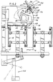
- Figures 1 and 2 illustrate a forming, filling and sealing machine 10 embodying a pour spout fitment applicator 12, and including a conveyor 14 carrying thermoplastic-coated cartons 16 having open-topped upper end closures 18. An opening 20 is formed in one panel 22 of each end closure 18.
- the applicator 12 is mounted on the machine 10 intermediate the usual indexable turret mechanism T including a plurality of mandrels M and the source S of a selected liquid.
- the conveyor 14 comprises two endless chains 24 and 26 spaced a predetermined distance d apart, within which a series of closely spaced apart cartons 16 are carried, with the panel 22 bearing the opening 20 facing toward one of the chains 24.
- the pour spout fitment applicator 12 includes a rotatable shaft 28 having a narrow cam 30 secured thereto.
- the cam 30 includes an outer arcuate surface 32.
- a chute 34 extends downwardly at a predetermined angle above the applicator 12.
- the chute 34 is adapted to hold a row of pour spout fitments 36 with flanges 37 thereon slidably aligned therein, as received from external loading means, such as a vibratory parts feeder (not shown).
- a vibratory parts feeder automatically orients a load of fitments 36 and feeds them in their oriented attitude to the chute 34.
- An escapement device 38 includes a segment 40 pivotally connected by a pivot pin 42 to the distal end of the chute 34.
- a spring 43 mounted around the pivot pin 42 urges the segment 40 clockwise about the pivot pin while the line-up of fitments 36 is retained in the chute 34.
- the escapement device 38 also includes any suitable release mechanism, such as a cylinder 44 and associated stop member 45, adapted to release one fitment 36 into the segment 40 each time the segment is returned to an aligned relationship with the chute 34, as will be explained.
- a retaining clip 47 holds a fitment 36 loosely in the segment 40.
- An anvil 46 is also secured to the shaft 28 adjacent the cam 30.
- a vacuum cup 48 is mounted on the end portion of the anvil 46.
- An ultrasonic sealer 50 includes a retractable horn 52 having an axis aligned with the opening 20 in the panel 22.
- a typical linkage and toggle system represented as 54, is operatively connected to the shaft 28, serving to reciprocally rotate same in unison with the indexing of the cartons 16 by the conveyor 14.
- the linkage and toggle system 54 rotates the shaft 28 in a counterclockwise direction in Figure 2, thereby rotating the anvil 46 and the cam 30 out of the carton path and such that the surface 32 is rotated past the segment 40.
- the spring 43 pivots the segment from the position shown in solid lines in Figure 2 to the position shown in phantom.
- the vacuum cup 48 on the end portion of the anvil 46 engages and receives the fitment 36 from the segment 40.
- the anvil 46 and vacuum cup 48 rotate the fitment 36 into the open top of the now indexed carton, as shown in Figure 2, to thereby project the fitment outwardly through the opening 20, and engage the flange 37 against the inner surface of the panel 22 around the opening.
- the ultrasonic sealer 50 and retractable horn 52 move to the right in Figure 2, into contact with the outer surface of the panel 22 around the portion of the fitment 36 extended therethrough, where it serves to weld the flange 37 of the fitment to the inner surface of the panel 22, after which the horn retracts.
- the cam 30 and anvil 46 are then rotated by the system 54 out of the open top closure 18 for the next cycle, and the cartons 16 are indexed forward toward the usual filling and top sealing stations of the forming, filling and sealing machine 10.
- the applicator is particularly suitable for co-operation with an indexing conveyor of a high-production, forming, filling and sealing machine.
- an indexing conveyor of a high-production, forming, filling and sealing machine For a machine which indexes closely arrayed cartons two or more at a time along one path, multiple applicators may be employed side-by-side to accommodate closely adjacent cartons.
Landscapes
- Engineering & Computer Science (AREA)
- Mechanical Engineering (AREA)
- Making Paper Articles (AREA)
- Closing Of Containers (AREA)
Claims (9)
- Applikator zum Anbringen von Ansätzen in einer Wand (22) eines Behälters (16) mit offenem Ende, mit einem Schwingantriebselement (28), einem Ansatzhalter (48) der von dem Antriebselement (28) zwischen einer Ansatzaufnahmeposition, in der ein Ansatz (36) in den Ansatzhalter (48) geladen wird, und einer zweiten Position verschwenkbar ist, und einer Zuführeinrichtung (38) zum Zuführen von Ansätzen (36) zu dem Ansatzhalter (48) in der Ansatzaufnahmeposition, dadurch gekennzeichnet, daß das Schwenken des Ansatzhalters (48) eine einzige Bewegung, nämlich eine Drehbewegung, von der Ansatzaufnahmeposition zu einer zweiten Position umfaßt, wobei der Ansatzhalter (48) den Ansatz (36) während der Annäherung an die zweite Position in die Wand (22) einsetzt.
- Applikator nach Anspruch 1, bei dem die Zuführeinrichtung (38) aufweist: eine Rinne (34) zum ausgerichteten Aufnehmen von Ansätzen (36), ein zur Aufnahme jeweils eines Ansatzes (36) von der Rinne (34) ausgebildetes schwenkbares Endsegment (40) der Rinne (34), eine Vorspanneinrichtung (43) zum Drücken des Endsegments (40) in Richtung auf den Ansatzhalter (48), und eine bogenförmige Nockenfläche (32) eines an dem Antriebselement (28) befestigten Nockens (30), der in der Lage ist, das Endsegment (40) entgegen der Kraft der Vorspanneinrichtung (43) wieder in Ausrichtung auf die Rinne (34) zu bringen, während ein Amboß (46), der den Ansatzhalter (48) an dem Antriebselement (28) anbringt, in den Behälter (16) mit offenem Ende gedreht wird.
- Applikator nach Anspruch 2, bei dem der Nocken (30) und der Amboß (46) nebeneinander an dem Antriebsteil (28) derart befestigt sind, daß Endbereiche derselben gemeinsam in den Behälter (16) mit offenem Ende eintreten und diesen verlassen.
- Applikator nach Anspruch 1, 2 oder 3 und ferner mit einem Gestänge-und-Kniehebelsystem (54) zum Schwenken des Antriebselements (28).
- Applikator nach einem der vorhergehenden Ansprüche und ferner mit einer Ultraschallsiegeleinrichtung (50) mit einer zurückziehbaren Spitze (52) zum Versigeln des Ansatzes (36) mit der Wand (22) und zum Angreifen an einer Fläche der Wand (22), während sich der Ansatzhalter (48) hinter dem Ansatz (36) befindet, um so den Ansatz (36) mit der gegenüberliegenden Fläche der Wand (22) zu versiegeln.
- Kombination aus einem Applikator nach einem der vorhergehenden Ansprüche und einem Förderer (14) zum Vorschieben des Behälters (16) in eine Position unterhalb des Ansatzhalters (48), wobei das Schwenken des Ansatzhalters (48) in einer Ebene erfolgt, die quer zu der Bewegungsbahn des Behälters entlang dem Förderer (14) verläuft.
- Verfahren zum Einsetzen eines Ansatzes (36) in eine Wand (22) eines Behälters (16) mit offenem Ende, mit den Schritten des Verschwenkens eines Ansatzhalters (48) zwischen einer Ansatzaufnähmeposition und einer zweiten Position, des Zuführens von Ansätzen zu dem Ansatzhalter (48) in der Ansatzaufnahmeposition, und des Drehens des Ansatzhalters (48) und damit des Ansatzes (36) aus der Ansatzaufnahmeposition in die zweite Position in einer einzigen Bewegung, nämlich einer Drehbewegung, dadurch gekennzeichnet, daß während der Annäherung des Ansatzhalters (48) an die zweite Position, dieser den Ansatz (36) in die Wand (22) einsetzt.
- Verfahren nach Anspruch 7, bei dem der Ansatz (36) ein Ausgußstutzen (36) ist und die Wand (22) des Behälters (16) eine obere Verschlußbahn (22) eines Kartons (16) ist.
- Verfahren nach Anspruch 7 oder 8, bei dem das Verschwenken des Ansatzhalters (48) quer zur Vorschubrichtung des Behälters (16) an dem Ansatzhalter (48) vorbei verläuft.
Priority Applications (1)
| Application Number | Priority Date | Filing Date | Title |
|---|---|---|---|
| EP96115280A EP0749904B1 (de) | 1993-04-12 | 1994-04-11 | Vorrichtung und verfahren zum anbringen von ausgiessern |
Applications Claiming Priority (2)
| Application Number | Priority Date | Filing Date | Title |
|---|---|---|---|
| US08/045,347 US5267934A (en) | 1993-04-12 | 1993-04-12 | Carton pour spout fitment applicator |
| US45347 | 1993-04-12 |
Related Child Applications (2)
| Application Number | Title | Priority Date | Filing Date |
|---|---|---|---|
| EP96115280A Division EP0749904B1 (de) | 1993-04-12 | 1994-04-11 | Vorrichtung und verfahren zum anbringen von ausgiessern |
| EP96115280.8 Division-Into | 1996-09-24 |
Publications (2)
| Publication Number | Publication Date |
|---|---|
| EP0620152A1 EP0620152A1 (de) | 1994-10-19 |
| EP0620152B1 true EP0620152B1 (de) | 1997-06-04 |
Family
ID=21937367
Family Applications (2)
| Application Number | Title | Priority Date | Filing Date |
|---|---|---|---|
| EP96115280A Expired - Lifetime EP0749904B1 (de) | 1993-04-12 | 1994-04-11 | Vorrichtung und verfahren zum anbringen von ausgiessern |
| EP94302511A Expired - Lifetime EP0620152B1 (de) | 1993-04-12 | 1994-04-11 | Vorrichtung zum Anbringen von Ausgiessern |
Family Applications Before (1)
| Application Number | Title | Priority Date | Filing Date |
|---|---|---|---|
| EP96115280A Expired - Lifetime EP0749904B1 (de) | 1993-04-12 | 1994-04-11 | Vorrichtung und verfahren zum anbringen von ausgiessern |
Country Status (4)
| Country | Link |
|---|---|
| US (1) | US5267934A (de) |
| EP (2) | EP0749904B1 (de) |
| JP (1) | JPH071612A (de) |
| DE (2) | DE69403547T2 (de) |
Cited By (2)
| Publication number | Priority date | Publication date | Assignee | Title |
|---|---|---|---|---|
| US7413097B1 (en) | 2003-08-01 | 2008-08-19 | Portola Packaging, Inc. | Tamper-evident closure and method of making same |
| WO2024188940A1 (en) * | 2023-03-10 | 2024-09-19 | Sig Services Ag | Spout applying device and spout applying method |
Families Citing this family (31)
| Publication number | Priority date | Publication date | Assignee | Title |
|---|---|---|---|---|
| US5484374A (en) * | 1991-10-25 | 1996-01-16 | Nimco Corporation | Method and apparatus for attaching a spout to a container |
| US5366433A (en) * | 1993-06-24 | 1994-11-22 | Mccormick Charles M | Safety clutch and its use in capping milk cartons |
| US5435803A (en) * | 1993-07-01 | 1995-07-25 | Elopak Systems A.G. | Container fitment applicator |
| US5473857A (en) * | 1993-11-16 | 1995-12-12 | International Paper Company | System integration for hot melt sealing of fitments in-line with form/fill/seal machine |
| US5467581A (en) * | 1994-04-25 | 1995-11-21 | W. R. Grace & Co.-Conn. | Apparatus and process for positioning a fitment |
| US5601669A (en) * | 1994-10-04 | 1997-02-11 | Portola Packaging, Inc. | Apparatus and method for attaching fitments to cartons |
| US6464096B2 (en) | 1995-01-30 | 2002-10-15 | Portola Packaging, Inc. | Fitment having removable membrane |
| US5957312A (en) | 1995-01-30 | 1999-09-28 | Portola Packaging, Inc. | Fitment having removable membrane |
| IT1278172B1 (it) * | 1995-01-30 | 1997-11-17 | Gianpaolo Belloli | Metodo ed apparecchiatura per la realizzazione di contenitori per prodotti liquidi o polverulenti, particolarmente alimentari o chimici |
| US6129228A (en) * | 1995-01-30 | 2000-10-10 | Portola Packaging, Inc. | Apparatus and method for transporting fitment and fitment therefor |
| US5716471A (en) * | 1995-10-30 | 1998-02-10 | Elopak Systems Ag | Method for securing articles to laminates |
| US6066081A (en) * | 1995-11-03 | 2000-05-23 | Nimco Corporation | Method and apparatus for attaching a fitment to and sterilizing a container |
| US5964687A (en) | 1996-07-16 | 1999-10-12 | Elopak Systems Ag | Container fitment applicator |
| US5819504A (en) * | 1996-09-20 | 1998-10-13 | Tetra Laval Holdings & Finance, S.A. | Process and apparatus for applying fitments to a carton |
| US5759143A (en) * | 1996-11-01 | 1998-06-02 | Portola Packaging, Inc. | Fitment applicator |
| WO1998036977A2 (en) * | 1997-02-20 | 1998-08-27 | Elopak Systems Ag | Apparatus and methods for securing articles to containers |
| US5857309A (en) * | 1997-03-28 | 1999-01-12 | Tetra Laval Holdings & Finance, S.A. | Apparatus for sterilizing a spout assembly of a container |
| EP1293435A1 (de) | 1997-10-24 | 2003-03-19 | Elopak Systems Ag | Vorrichtung zum Anbringen von Teilen an einem Material |
| WO1999029152A2 (en) * | 1997-10-24 | 1999-06-17 | Elopak Systems Ag | Machine for applying parts to articles |
| US5983599A (en) * | 1998-04-23 | 1999-11-16 | Tetra Laval Holdings & Finance, S.A. | Offset rotary anvils for applying fitments to carton |
| US6145275A (en) * | 1998-06-11 | 2000-11-14 | Tetra Laval Holdings & Finance, Sa | Apparatus for applying a fitment to pre-formed carton at the infeed to a packaging machine |
| US6079185A (en) * | 1998-07-31 | 2000-06-27 | Tetra Laval Holdings & Finance, Sa | Induction heat sealing of a closure to a container |
| GB9821177D0 (en) | 1998-09-30 | 1998-11-25 | Elopak Systems | Applicator and method |
| DE19915150A1 (de) * | 1999-03-26 | 2000-10-12 | Sig Combibloc Gmbh | Verfahren zur Herstellung einer Verbundpackung und nach dem Verfahren hergestellte Verbundpackung |
| US6807792B2 (en) * | 2000-12-18 | 2004-10-26 | Tetra Laval Holdings & Finance, Sa | Spout singulator for closure feed system |
| JP4639479B2 (ja) * | 2001-01-26 | 2011-02-23 | 四国化工機株式会社 | 容器口栓取付装置 |
| US7500940B2 (en) * | 2004-10-05 | 2009-03-10 | Nimco Corporation | Spout applicator |
| US8104250B2 (en) * | 2004-11-16 | 2012-01-31 | Elopak Systems Ag | Apparatus for use in and method of attachiing cap-form fitments to containers |
| GB0709063D0 (en) * | 2007-05-11 | 2007-06-20 | Elopak Systems | Method and apparatus |
| CN105905366B (zh) * | 2016-06-27 | 2019-04-02 | 薛桦钧 | 屋顶包的封装设备 |
| CN109732990B (zh) * | 2019-03-13 | 2023-12-22 | 浙江国豪机械有限公司 | 一种包装盒成型机用超声波定型设备 |
Family Cites Families (5)
| Publication number | Priority date | Publication date | Assignee | Title |
|---|---|---|---|---|
| DE3163709D1 (en) * | 1980-02-22 | 1984-06-28 | Dainippon Printing Co Ltd | Method and apparatus for the fabrication of a bag-in-box package |
| US4456118A (en) * | 1981-11-18 | 1984-06-26 | Ex-Cell-O Corporation | Single to dual indexing carton transfer mechanism |
| US4512136A (en) * | 1982-08-23 | 1985-04-23 | Trinity Associates, A Partnership Of The State Of Pennsylvania | Fitment attachment methods in horizontal form/fill/seal machines |
| US4788811A (en) * | 1986-05-17 | 1988-12-06 | Dai Nippon Insatsu Kabushiki Kaisha | Process and apparatus for assembling and liquor-charging of packages of paper and the like |
| GB8926635D0 (en) * | 1989-11-24 | 1990-01-17 | Rutter Raymond | Cap and pour spout applicator |
-
1993
- 1993-04-12 US US08/045,347 patent/US5267934A/en not_active Expired - Fee Related
-
1994
- 1994-04-11 EP EP96115280A patent/EP0749904B1/de not_active Expired - Lifetime
- 1994-04-11 DE DE69403547T patent/DE69403547T2/de not_active Expired - Fee Related
- 1994-04-11 DE DE69418901T patent/DE69418901T2/de not_active Expired - Fee Related
- 1994-04-11 EP EP94302511A patent/EP0620152B1/de not_active Expired - Lifetime
- 1994-04-12 JP JP6098222A patent/JPH071612A/ja active Pending
Cited By (2)
| Publication number | Priority date | Publication date | Assignee | Title |
|---|---|---|---|---|
| US7413097B1 (en) | 2003-08-01 | 2008-08-19 | Portola Packaging, Inc. | Tamper-evident closure and method of making same |
| WO2024188940A1 (en) * | 2023-03-10 | 2024-09-19 | Sig Services Ag | Spout applying device and spout applying method |
Also Published As
| Publication number | Publication date |
|---|---|
| DE69418901T2 (de) | 2000-02-24 |
| JPH071612A (ja) | 1995-01-06 |
| EP0749904A2 (de) | 1996-12-27 |
| DE69403547T2 (de) | 1998-01-29 |
| DE69403547D1 (de) | 1997-07-10 |
| EP0749904B1 (de) | 1999-06-02 |
| EP0620152A1 (de) | 1994-10-19 |
| DE69418901D1 (de) | 1999-07-08 |
| EP0749904A3 (de) | 1997-02-12 |
| US5267934A (en) | 1993-12-07 |
Similar Documents
| Publication | Publication Date | Title |
|---|---|---|
| EP0620152B1 (de) | Vorrichtung zum Anbringen von Ausgiessern | |
| US5435803A (en) | Container fitment applicator | |
| US5473857A (en) | System integration for hot melt sealing of fitments in-line with form/fill/seal machine | |
| US5110041A (en) | In-line fitment sealing apparatus and method | |
| EP0962391B1 (de) | Verfahren zum Anbringen von Ausgiesstüllen an Behältern und Vorrichtung zur Verwendung in demselben | |
| EP0781228B1 (de) | System zum anbringen von ausgiesstüllen an kartons | |
| US5484374A (en) | Method and apparatus for attaching a spout to a container | |
| US6085489A (en) | Spout mandrel with energy ring | |
| US7867156B2 (en) | Spout applicator | |
| US6892508B2 (en) | Apparatus and methods for securing articles to containers | |
| AU674166B2 (en) | Method and apparatus for folding bottom panels of a carton blank | |
| EP1227041B1 (de) | Vorrichtung zum Anbringen eines Behälterverschlusses | |
| US3996724A (en) | Rotary carton closing and sealing apparatus | |
| US20080276576A1 (en) | Universal top sealing system for gable top package | |
| WO1999054124A1 (en) | Offset rotary anvils for applying fitments to a carton | |
| US6145275A (en) | Apparatus for applying a fitment to pre-formed carton at the infeed to a packaging machine | |
| US4846915A (en) | Apparatus for indexing and feeding a fitment web and related method | |
| US5100369A (en) | System for continuous high speed application of fitments to carton blanks | |
| WO2011083322A9 (en) | Method of and apparatus for applying fitments to containers | |
| US6662524B2 (en) | Closure applicator with swinging arm anvil | |
| WO2000018649A1 (en) | Pour spout fitment applicator | |
| WO2026018175A1 (en) | Automatic packaging unit filling and sealing containers made of heat-sealable material and method for operating such a unit | |
| WO2026047459A2 (en) | Machine for forming a package made of flexible material |
Legal Events
| Date | Code | Title | Description |
|---|---|---|---|
| PUAI | Public reference made under article 153(3) epc to a published international application that has entered the european phase |
Free format text: ORIGINAL CODE: 0009012 |
|
| AK | Designated contracting states |
Kind code of ref document: A1 Designated state(s): DE GB IT SE |
|
| 17P | Request for examination filed |
Effective date: 19941202 |
|
| 17Q | First examination report despatched |
Effective date: 19951025 |
|
| GRAG | Despatch of communication of intention to grant |
Free format text: ORIGINAL CODE: EPIDOS AGRA |
|
| GRAH | Despatch of communication of intention to grant a patent |
Free format text: ORIGINAL CODE: EPIDOS IGRA |
|
| RAP1 | Party data changed (applicant data changed or rights of an application transferred) |
Owner name: ELOPAK SYSTEMS AG |
|
| GRAH | Despatch of communication of intention to grant a patent |
Free format text: ORIGINAL CODE: EPIDOS IGRA |
|
| GRAA | (expected) grant |
Free format text: ORIGINAL CODE: 0009210 |
|
| AK | Designated contracting states |
Kind code of ref document: B1 Designated state(s): DE GB IT SE |
|
| DX | Miscellaneous (deleted) | ||
| ITF | It: translation for a ep patent filed | ||
| REF | Corresponds to: |
Ref document number: 69403547 Country of ref document: DE Date of ref document: 19970710 |
|
| PLBE | No opposition filed within time limit |
Free format text: ORIGINAL CODE: 0009261 |
|
| STAA | Information on the status of an ep patent application or granted ep patent |
Free format text: STATUS: NO OPPOSITION FILED WITHIN TIME LIMIT |
|
| 26N | No opposition filed | ||
| REG | Reference to a national code |
Ref country code: GB Ref legal event code: IF02 |
|
| PGFP | Annual fee paid to national office [announced via postgrant information from national office to epo] |
Ref country code: GB Payment date: 20050314 Year of fee payment: 12 |
|
| PGFP | Annual fee paid to national office [announced via postgrant information from national office to epo] |
Ref country code: DE Payment date: 20050316 Year of fee payment: 12 |
|
| PGFP | Annual fee paid to national office [announced via postgrant information from national office to epo] |
Ref country code: SE Payment date: 20050321 Year of fee payment: 12 |
|
| PG25 | Lapsed in a contracting state [announced via postgrant information from national office to epo] |
Ref country code: GB Free format text: LAPSE BECAUSE OF NON-PAYMENT OF DUE FEES Effective date: 20060411 |
|
| PG25 | Lapsed in a contracting state [announced via postgrant information from national office to epo] |
Ref country code: SE Free format text: LAPSE BECAUSE OF NON-PAYMENT OF DUE FEES Effective date: 20060412 |
|
| PGFP | Annual fee paid to national office [announced via postgrant information from national office to epo] |
Ref country code: IT Payment date: 20060430 Year of fee payment: 13 |
|
| PG25 | Lapsed in a contracting state [announced via postgrant information from national office to epo] |
Ref country code: DE Free format text: LAPSE BECAUSE OF NON-PAYMENT OF DUE FEES Effective date: 20061101 |
|
| EUG | Se: european patent has lapsed | ||
| GBPC | Gb: european patent ceased through non-payment of renewal fee |
Effective date: 20060411 |
|
| PG25 | Lapsed in a contracting state [announced via postgrant information from national office to epo] |
Ref country code: IT Free format text: LAPSE BECAUSE OF NON-PAYMENT OF DUE FEES Effective date: 20070411 |