EP0619789B1 - Gleisbesetzungsmeldeanlage - Google Patents
Gleisbesetzungsmeldeanlage Download PDFInfo
- Publication number
- EP0619789B1 EP0619789B1 EP92924779A EP92924779A EP0619789B1 EP 0619789 B1 EP0619789 B1 EP 0619789B1 EP 92924779 A EP92924779 A EP 92924779A EP 92924779 A EP92924779 A EP 92924779A EP 0619789 B1 EP0619789 B1 EP 0619789B1
- Authority
- EP
- European Patent Office
- Prior art keywords
- master unit
- slave
- track
- unit
- master
- Prior art date
- Legal status (The legal status is an assumption and is not a legal conclusion. Google has not performed a legal analysis and makes no representation as to the accuracy of the status listed.)
- Expired - Lifetime
Links
- 230000011664 signaling Effects 0.000 claims abstract description 6
- 230000000977 initiatory effect Effects 0.000 claims abstract description 5
- 238000012795 verification Methods 0.000 claims abstract description 4
- 238000013459 approach Methods 0.000 claims description 7
- 239000003990 capacitor Substances 0.000 claims description 5
- 230000000007 visual effect Effects 0.000 claims description 2
- 230000000063 preceeding effect Effects 0.000 claims 1
- 230000002238 attenuated effect Effects 0.000 abstract description 2
- 230000003213 activating effect Effects 0.000 description 1
- 230000001939 inductive effect Effects 0.000 description 1
Images

Classifications
-
- B—PERFORMING OPERATIONS; TRANSPORTING
- B61—RAILWAYS
- B61L—GUIDING RAILWAY TRAFFIC; ENSURING THE SAFETY OF RAILWAY TRAFFIC
- B61L29/00—Safety means for rail/road crossing traffic
- B61L29/08—Operation of gates; Combined operation of gates and signals
- B61L29/18—Operation by approaching rail vehicle or train
- B61L29/22—Operation by approaching rail vehicle or train electrically
- B61L29/226—Operation by approaching rail vehicle or train electrically using track-circuits, closed or short-circuited by train or using isolated rail-sections
Definitions
- This invention relates to track occupation warning systems for railway lines and has application, for example, to railway crossings, particularly for sections of track where there are no lineside cables available for the provision of telephones at such crossings.
- US-A-3740550 discloses a railway crossing signalling system using coded digital signals impressed on the tracks for actuation of a crossing relay, the presence of a train at the crossing location causing shunting of the signals and an indication from the relay.
- the object of the invention is to provide a warning system which is particularly suitable for use at railway crossings and which can be adapted to other applications e.g. for trackside workers, or for train drivers.
- a track occupation warning system comprises a master unit positioned at a predetermined position along a length of track, eg at a crossing, or signalling point, and a slave unit for each directional working of the track positioned along the track at a predetermined distance from said master unit, said master and slave units each being electrically connected to the running lines of the track, said master unit comprising operating means for initiating, generating and transmitting a predetermined series of pulses forming a unique encoded message to the or each slave unit via said running lines and first receiving means for receiving and verifying a response from the or each slave unit, and the or each said slave unit comprising second receiving means for receiving and verifying an encoded message from said master unit, and response means for generating and transmitting a response in the form of its own unique encoded message only if an encoded message from said master unit is verified by said second receiving means, the system being such that, if a vehicle is either closely approaching a slave unit, or is within the section of track between said slave unit and master unit, any encode
- the master unit includes display means which are connected to said first receiving means so as to provide a visual indication to the user as to whether or not the track length is occupied by a vehicle.
- the operating means of the master unit and response means of the or each slave unit comprise an electrical circuit including an inverter for generating via capacitors different levels and/or states of impulse, e.g. positive and negative going impulses, and an encoder controlling said positive and negative impulses and producing a predetermined sequence thereof, said sequence constituting a unique encoded message which is transmitted between units via said running rails, each electrical circuit also including decoder means for receiving and verifying encoded messages.
- an inverter for generating via capacitors different levels and/or states of impulse, e.g. positive and negative going impulses
- an encoder controlling said positive and negative impulses and producing a predetermined sequence thereof, said sequence constituting a unique encoded message which is transmitted between units via said running rails
- each electrical circuit also including decoder means for receiving and verifying encoded messages.
- its electrical circuit may conveniently include a press-button or other suitable switch, particularly for crossing or track-side applications.
- the circuit may be initiated by a remotely operable switch in response to an infra-red or other suitable remote control signal, e.g. operated by the driver of an approaching train and directed via a trackside relay.
- the system may be interrogated and operated automatically by an approaching train.
- the system may be operated manually by the driver alighting from his vehicle and actuating an appropriate switch.
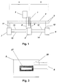
- the system is associated with a level crossing 1 for a single track 2 comprising a pair of running lines 3 along which trains can pass in both directions under signal control.
- the system itself comprises a master unit 4 on one approach to the crossing 1, a sub-master unit 5 on the other approach to the crossing, and two slave units 6, 7 positioned at a predetermined distance along the track on each side of the crossing.
- the master and sub-units are electrically connected via a link 8 and that the master and slave units are electrically connected via pairs of cables 9, 10, 11 respectively to the running rails 3.
- the electrical connection is such that data 12, 13 can be transmitted from the master to each slave unit and that data responses 14, 15 can be transmitted from each slave unit back to the master unit.
- the distance X of the slave units along the track on each side of the crossing is determined so as to provide a minimum safe time period for a user to cross.
- the running time of a train along the track in the vicinity of the slave unit would be such as to reach the crossing within the safe time period a warning of the presence of the train would be displayed to the user.
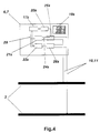
- the master unit 4 has an operating circuit 16 comprising sequential logic 17 which when initiated by pressing a button 18, or other appropriate switch, connects the circuit to a battery 19 for activating, in sequence, an encoder 20, inverter 21, decoder 22 and a display 23.
- the inverter 21 is connected via capacitors 24 and a switch 25 controlled by the encoder 20 to the running lines 3 via the connecting cables 9.
- the circuit also includes a receiver 26 between said cables 9 and the decoder 22, for controlling an output signal from the decoder indicative of the presence or absence of a train, which is fed to the display 23.
- the sub-master unit 5 is not connected to the running lines but only to the master unit 4 via a cable or remote control link 8.
- No operating circuit is provided; only a display 27 to which the link 8 is connected.
- the link 8 includes a push button 28, or other appropriate switch, which can be pressed by a user on that approach side of the crossing, which will initiate the operating circuit 16 of the master unit.
- impulse cables, inductive loops, or other appropriate remote operating means can be laid across the approaches to the crossing and connected into the operating circuit 16 to avoid the need for the driver alighting from the vehicle.
- each slave unit 6, 7 has a response circuit 29 which is basically the same as the operating circuit 16 of master unit 4 and also its own battery 19S and receiver 26S.
- the response circuit includes sequential logic 17S, an encoder 20S, inverter 21S, decoder 22S, capacitor 24S and an encoder switch 25S, the circuit being connected to the running lines 3 via the cables 10, 11 respectively. It will be appreciated that neither an operating switch, nor a display is needed for the slave units.
- the inverter 21 In operation of the system, when the push button 18 or 28 of the master or sub-master unit 4, 5 is pressed by a user to activate the operating circuit, the inverter 21 generates a voltage to produce a series of positive and negative charges from the capacitors 24 in the form of spiked voltages and these latter are sent in a timed sequence controlled by the encoder 20 via the switch 25 to the running lines 3. In this way a unique encoded message comprising a particular sequence of positive and negative spiked voltages are transmitted via the running rails 3 to receivers 26S of the slave units 6, 7. Each receiver 26S is programmed to activate its associated response circuit 29 only if it recognises and verifies the particular encoded message. Thus, if no train is approaching i.e.
- the encoded message from the master unit will be verifiable. However, if a train is present, its wheel contact with the rails will act as a shunt and will cause such a significant attenuation to the signal that it will not be verifiable.
- each slave unit will generate its own encoded message in the response circuit for transmitting back to the receiver means of the master unit 4 for verification and, to ensure the messages are not adulterated by interference with each other, preferably the electrical circuit of one of the slave units includes a delay so that its message can be processed by the master unit after it has processed the message from the other slave unit.
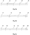
- the system may be extended by the use of further slave units, each with its own receiver and response means so that a message from the master unit to the outermost slave units and response messages from the outermost slave units can be passed serially through the intermediate slave units via the running lines 6.
- each master unit has its respective outer slave unit 7a, 7b, and it will be appreciated that the two master units would provide an encoded message which may be common to both master units.
- each master unit may have its own unique encoded message, in which case the receiving means of the common slave unit 7c would be designed to receive and verify both encoded messages so as to be able to respond to the appropriate master unit.
- the spacing between the crossings is close enough for the two master units 4a and 4b to interrogate each other with a common, or different encoded message, hence dispensing with the need for slave unit 7c.
- each can nevertheless have two associate slave units 7a1, 7a2 and 7b1, 7b2 respectively, in which case the slave units are effectively overlapping each other. It will be appreciated here that the two master units would have different encoded messages to ensure correct interrogation by their respective slave units.
Landscapes
- Engineering & Computer Science (AREA)
- Mechanical Engineering (AREA)
- Train Traffic Observation, Control, And Security (AREA)
- Electric Propulsion And Braking For Vehicles (AREA)
Claims (12)
- Gleisbesetzungs-Meldeanlage mit Sende- und Empfangseinheiten (4, 6, 7), welche entlang einer zu überwachenden Gleislänge (2) beabstandet und elektrisch (an Punkten 10, 11) durch die Fahrspuren (3) des Gleises verbunden sind, wobei die Sende- und Empfangseinheiten eine an einer vorgegebenen Position entlang des Gleises positionierte Haupteinheit (4) und eine mit einem vorgegebenen Abstand zur Haupteinheit angeordnete Nebeneinheit (6, 7) für jede Betriebsrichtung des Gleises aufweisen, wobei die Haupteinheit eine Betätigungseinrichtung (16) zum Initiieren, Erzeugen und Übertragen einer vorbestimmten Impulsreihe aufweist, welche eine verschlüsselte Nachricht zur oder zu jeder Nebeneinheit durch die Fahrspuren bilden, sowie erste Empfangseinheiten (26), welche eine Antwort von der oder jeder Nebeneinheit empfangen und prüfen, und wobei die oder jede Nebeneinheit zweite Empfangseinheiten (26S) zum Empfangen und Prüfen einer verschlüsselten Nachricht von der Haupteinheit und eine Ansprecheinrichtung (29) zum Erzeugen und Übertragen einer Antwort in Form ihrer eigenen eindeutigen verschlüsselten Nachricht, wenn ausschließlich eine verschlüsselte Nachricht von der Haupteinheit durch die zweiten Empfangseinheiten geprüft wird, aufweist, wobei die Anlage durch Fahrzeugkontakt mit den Fahrschienen funktionsfähig ist, wenn sich ein Fahrzeug entweder einer Nebeneinheit nahe annähert oder innerhalb der Gleislänge zwischen der Nebeneinheit und der Haupteinheit befindet, um jegliche verschlüsselte Nachricht von der Haupteinheit in ausreichendem Maße abzuschwächen, so daß eine Prüfung durch die zweiten Empfangseinheiten verhindert wird.
- Anlage nach Anspruch 1, dadurch gekennzeichnet, daß die Betätigungseinrichtung (16) der Haupteinheit und die Ansprecheinrichtung (29) der oder jeder Nebeneinheit eine elektrische Schaltung mit einem Wechselrichter (21, 21S) zum Erzeugen verschiedener Niveaus und/oder Impulszustände durch Kondensatoren (24, 24S) und eine Kodiereinrichtung (20, 20S) aufweisen, welche die positiven und negativen Impulse steuert und davon eine vorgegebene Reihenfolge erzeugt, wobei die Reihenfolge eine eindeutige verschlüsselte Nachricht bildet, welche zwischen den Haupt- und Nebeneinheiten durch die Fahrspuren (3) übertragen wird, und jede elektrische Schaltung zudem einen Dekoder (22, 22s) zum Prüfen der verschlüsselten Nachrichten aufweist, welche von den ersten oder zweiten Empfangseinheiten (26, 26S) empfangen wurden.
- Anlage nach Anspruch 2, dadurch gekennzeichnet, daß sich die Impulse positiv und negativ vorwärts bewegen.
- Anlage nach Anspruch 1, 2 oder 3, für eine Gleislänge, welche die normale Betriebslänge der Anlage übersteigt, dadurch gekennzeichnet, daß weitere Nebeneinheiten (6, 7) entlang der Gleislänge angeordnet sind, von denen jede ihre eigene Empfangs- und Ansprecheinheit aufweist, so daß eine Nachricht von der Haupteinheit (4) zu den äußersten Nebeneinheiten und Ansprechnachrichten von den äußersten Nebeneinheiten seriell durch die dazwischen angeordneten Nebeneinheiten mittels der Fahrschienen hindurchlaufen können.
- Anlage nach einem der Ansprüche 1 - 4, dadurch gekennzeichnet, daß die Haupteinheit (4) Anzeigeeinheiten (23) aufweist, welche mit den ersten Empfangseinheiten (26) verbunden sind, so daß eine visuelle Anzeige für den Benutzer, ob die Gleislänge durch ein Fahrzeug besetzt ist oder nicht, vorgesehen wird.
- Anlage nach Anspruch 5, für eine Eisenbahnkreuzung oder gleisseitige Anwendung, dadurch gekennzeichnet, daß die Haupteinheit (4) an der Kreuzung oder gleisseitigen Position und eine Nebeneinheit (6, 7) entlang der Eisenbahnspuren mit einem vorgegebenen, zum Vorsehen einer Sicherheitswarnung durch die Anzeigeeinheit (23) für das Annähern oder die Anwesenheit eines Zuges ausreichenden Abstand vorgesehen sind, und daß die elektrische Schaltung (16) der Haupteinheit einen Schalter zum Initiieren der Anlage aufweist.
- Anlage nach Anspruch 6, für eine Eisenbahnkreuzung, dadurch gekennzeichnet, daß die Haupteinheit (4) an einem Zugang zur Kreuzung und eine zusätzliche Haupteinheit (5) an dem anderen Zugang zur Kreuzung vorgesehen sind, und daß die zusätzliche Haupteinheit elektrisch mit der Haupteinheit verbunden ist und ihren eigenen Schalter (28) für das Initiieren durch einen Benutzer aufweist.
- Anlage nach den Ansprüchen 1 oder 2, für die Anwendung von Signalen, dadurch gekennzeichnet, daß die Nebeneinheiten (6, 7) entlang der Länge des mit Signal zu versehenden Gleisabschnittes angeordnet sind und die Haupteinheit (4) innerhalb der Abschnittlänge vorgesehen ist, und daß die elektrische Schaltung der Haupteinheit so angeordnet ist, daß sie durch einen aus der Ferne betreibbaren Schalter in Abhängigkeit von einem Infrarotsignal oder einem anderen entfernten Signal initiiert wird, welches durch die Zugbelegschaft oder durch den Zug per se automatisch abfragend betätigt wird.
- Anlage nach Anspruch 8 und mit einem aus der Ferne betätigbaren Schalter, dadurch gekennzeichnet, daß das Signal durch ein gleisseitiges Relais gesteuert wird.
- Anlage nach einem der vorstehenden Ansprüche und bei welcher mehrere Nebeneinheiten (6, 7) mit der Haupteinheit (4) verbunden sind, dadurch gekennzeichnet, daß alle außer einer Nebeneinheit eine geeignete Verzögerung aufweisen, wobei die jeweiligen Nachrichten durch die Haupteinheit der Reihe nach verarbeitbar sind.
- Anlage nach einem der vorstehenden Ansprüche und bei welcher mehrere Haupteinheiten (4) und zugeordnete Nebeneinheiten (6, 7) angeordnet sind, dadurch gekennzeichnet, daß die oder jede Nebeneinheit Empfangseinheiten (26S) zum Empfangen und Prüfen mehrerer verschlüsselter Nachrichten aufweist, wobei die oder jede Nebeneinheit in Verbindung mit mehr als einer Haupteinheit verwendbar ist und auf die geeignete Haupteinheit ansprechen kann.
- Anlage nach einem der vorstehenden Ansprüche und bei welcher zwei Haupteinheiten (4a, 4b) vorgesehen sind, dadurch gekennzeichnet, daß die Haupteinheiten ausreichend nahe voneinander beabstandet sind, um voneinander abgefragt zu werden, wobei keine Nebeneinheit (7c) zwischen diesen erforderlich ist.
Applications Claiming Priority (3)
| Application Number | Priority Date | Filing Date | Title |
|---|---|---|---|
| GB9127459A GB2262828B (en) | 1991-12-28 | 1991-12-28 | Track occupation warning system |
| GB9127459 | 1991-12-28 | ||
| PCT/GB1992/002248 WO1993012963A1 (en) | 1991-12-28 | 1992-12-03 | Track occupation warning system |
Publications (2)
| Publication Number | Publication Date |
|---|---|
| EP0619789A1 EP0619789A1 (de) | 1994-10-19 |
| EP0619789B1 true EP0619789B1 (de) | 1995-09-20 |
Family
ID=10706871
Family Applications (1)
| Application Number | Title | Priority Date | Filing Date |
|---|---|---|---|
| EP92924779A Expired - Lifetime EP0619789B1 (de) | 1991-12-28 | 1992-12-03 | Gleisbesetzungsmeldeanlage |
Country Status (4)
| Country | Link |
|---|---|
| EP (1) | EP0619789B1 (de) |
| AU (1) | AU3089392A (de) |
| GB (1) | GB2262828B (de) |
| WO (1) | WO1993012963A1 (de) |
Families Citing this family (1)
| Publication number | Priority date | Publication date | Assignee | Title |
|---|---|---|---|---|
| CN100455467C (zh) * | 2005-04-29 | 2009-01-28 | 宝山钢铁股份有限公司 | 铁路道口机车临近信号触发报警装置 |
Family Cites Families (4)
| Publication number | Priority date | Publication date | Assignee | Title |
|---|---|---|---|---|
| GB1013568A (en) * | 1963-02-07 | 1965-12-15 | British Railways Board | Improvements relating to track circuits for railway signalling |
| US3740550A (en) * | 1971-01-11 | 1973-06-19 | Erico Prod Inc | Pulse coded railway signal system |
| US3974991A (en) * | 1975-08-27 | 1976-08-17 | Erico Rail Products Company | Railroad motion detecting and signalling system with repeater receiver |
| US5092544A (en) * | 1989-12-22 | 1992-03-03 | General Railway Signal Corp. | Highway crossing control system for railroads utilizing a communications link between the train locomotive and the crossing protection equipment |
-
1991
- 1991-12-28 GB GB9127459A patent/GB2262828B/en not_active Expired - Fee Related
-
1992
- 1992-12-03 EP EP92924779A patent/EP0619789B1/de not_active Expired - Lifetime
- 1992-12-03 AU AU30893/92A patent/AU3089392A/en not_active Abandoned
- 1992-12-03 WO PCT/GB1992/002248 patent/WO1993012963A1/en not_active Ceased
Also Published As
| Publication number | Publication date |
|---|---|
| AU3089392A (en) | 1993-07-28 |
| WO1993012963A1 (en) | 1993-07-08 |
| GB9127459D0 (en) | 1992-02-19 |
| GB2262828B (en) | 1995-06-14 |
| GB2262828A (en) | 1993-06-30 |
| EP0619789A1 (de) | 1994-10-19 |
Similar Documents
| Publication | Publication Date | Title |
|---|---|---|
| US4728063A (en) | Railway signalling system especially for broken rail detection | |
| NL194075C (nl) | Spoorwegsignalerings- en besturingsstelsel. | |
| US3888437A (en) | Vehicle control systems | |
| US5740046A (en) | Method to control in a track traffic system moving units, device for effecting of such control and process for installation of the device | |
| US3268727A (en) | Computer control for transit system | |
| US5459663A (en) | Cab signal apparatus and method | |
| US3772640A (en) | Vehicle control system with vehicle location error checking means | |
| US20040049327A1 (en) | Radio based automatic train control system using universal code | |
| JP2018207687A (ja) | 自動列車防護システム | |
| EP0619789B1 (de) | Gleisbesetzungsmeldeanlage | |
| US3810099A (en) | Means for providing a vehicle control signal containing direction and speed information | |
| US2816218A (en) | Control of manual block signal by a multiple frequency carrier system | |
| US3879004A (en) | Vehicle detection, signaling and communication system | |
| US3506823A (en) | Vehicle speed control system | |
| AU622722B2 (en) | Railway monitoring system | |
| JP3053806B1 (ja) | 車両制御装置 | |
| RU2388637C1 (ru) | Система управления движением поездов | |
| US3907237A (en) | Check-in, check-out track circuit arrangement | |
| US2874272A (en) | Two-direction coded track circuit control for railway signals | |
| US3339067A (en) | High frequency track circuits for railroads | |
| RU2159716C2 (ru) | Устройство для маневровой автоматической локомотивной сигнализации | |
| US2826685A (en) | Coded track circuit railway signaling system | |
| RU2775907C1 (ru) | Система интервального регулирования движения поездов с контролем изменения алгоритма работы | |
| JPH106994A (ja) | 踏切制御装置 | |
| US2287108A (en) | Railway traffic controlling apparatus |
Legal Events
| Date | Code | Title | Description |
|---|---|---|---|
| PUAI | Public reference made under article 153(3) epc to a published international application that has entered the european phase |
Free format text: ORIGINAL CODE: 0009012 |
|
| 17P | Request for examination filed |
Effective date: 19940621 |
|
| AK | Designated contracting states |
Kind code of ref document: A1 Designated state(s): IE |
|
| 17Q | First examination report despatched |
Effective date: 19950131 |
|
| GRAA | (expected) grant |
Free format text: ORIGINAL CODE: 0009210 |
|
| AK | Designated contracting states |
Kind code of ref document: B1 Designated state(s): IE |
|
| REG | Reference to a national code |
Ref country code: IE Ref legal event code: FG4D Free format text: 65319 |
|
| PLBE | No opposition filed within time limit |
Free format text: ORIGINAL CODE: 0009261 |
|
| STAA | Information on the status of an ep patent application or granted ep patent |
Free format text: STATUS: NO OPPOSITION FILED WITHIN TIME LIMIT |
|
| 26N | No opposition filed | ||
| PGFP | Annual fee paid to national office [announced via postgrant information from national office to epo] |
Ref country code: IE Payment date: 20011119 Year of fee payment: 10 |
|
| PG25 | Lapsed in a contracting state [announced via postgrant information from national office to epo] |
Ref country code: IE Free format text: LAPSE BECAUSE OF NON-PAYMENT OF DUE FEES Effective date: 20021203 |
|
| REG | Reference to a national code |
Ref country code: IE Ref legal event code: MM4A |