EP0619491A1 - Combined titration apparatus - Google Patents
Combined titration apparatus Download PDFInfo
- Publication number
- EP0619491A1 EP0619491A1 EP93105733A EP93105733A EP0619491A1 EP 0619491 A1 EP0619491 A1 EP 0619491A1 EP 93105733 A EP93105733 A EP 93105733A EP 93105733 A EP93105733 A EP 93105733A EP 0619491 A1 EP0619491 A1 EP 0619491A1
- Authority
- EP
- European Patent Office
- Prior art keywords
- unit
- coulometric
- titration
- volumetric
- basic
- Prior art date
- Legal status (The legal status is an assumption and is not a legal conclusion. Google has not performed a legal analysis and makes no representation as to the accuracy of the status listed.)
- Granted
Links
Images


Classifications
-
- G—PHYSICS
- G01—MEASURING; TESTING
- G01N—INVESTIGATING OR ANALYSING MATERIALS BY DETERMINING THEIR CHEMICAL OR PHYSICAL PROPERTIES
- G01N35/00—Automatic analysis not limited to methods or materials provided for in any single one of groups G01N1/00 - G01N33/00; Handling materials therefor
- G01N35/00584—Control arrangements for automatic analysers
- G01N35/00722—Communications; Identification
- G01N35/00732—Identification of carriers, materials or components in automatic analysers
-
- G—PHYSICS
- G01—MEASURING; TESTING
- G01N—INVESTIGATING OR ANALYSING MATERIALS BY DETERMINING THEIR CHEMICAL OR PHYSICAL PROPERTIES
- G01N31/00—Investigating or analysing non-biological materials by the use of the chemical methods specified in the subgroup; Apparatus specially adapted for such methods
- G01N31/16—Investigating or analysing non-biological materials by the use of the chemical methods specified in the subgroup; Apparatus specially adapted for such methods using titration
-
- G—PHYSICS
- G01—MEASURING; TESTING
- G01N—INVESTIGATING OR ANALYSING MATERIALS BY DETERMINING THEIR CHEMICAL OR PHYSICAL PROPERTIES
- G01N35/00—Automatic analysis not limited to methods or materials provided for in any single one of groups G01N1/00 - G01N33/00; Handling materials therefor
- G01N35/00584—Control arrangements for automatic analysers
- G01N35/00722—Communications; Identification
- G01N35/00732—Identification of carriers, materials or components in automatic analysers
- G01N2035/00742—Type of codes
- G01N2035/00762—Type of codes magnetic code
Definitions
- the invention relates to a volumetric or coulometric titration device.
- Titration devices can be used in a wide variety of fields for the chemical determination of one or more substances in samples.
- the amount of a substance sought can be determined by titration.
- a reagent with a known active substance content is metered precisely, which reacts in a known ratio with the substance sought.
- the amount of the reagent required up to a certain end point, which is usually recognized with an indicator electrode, is a measure of the amount of the substance to be determined.
- the specific reagent can be added in two different ways, either volumetric or coulometric.
- the reagent can be controlled very precisely
- the piston / cylinder unit (dosing unit) is fed to the titration vessel as the measured volume.
- the reagent is generated electrolytically in a titration vessel.
- generator electrodes are used, which are immersed in the content of the titration vessel.
- the current-time area is a measure of the amount of the added reagent and thus the substance to be determined.
- the known titrators work either by the volumetric or the coulometric method, i. that is, if there is a change of method, it is necessary to use the corresponding other titration device type.
- the purchase of the two devices leads to high costs.
- a titration device of the type mentioned at the outset with which an provided coulometric titration cell can be operated.
- an auxiliary device can be assigned that works according to the volumetric method.
- the invention has for its object to provide a titration device of the type mentioned, which is particularly versatile, inexpensive to buy and use and has a simple structure.
- a basic device which has a control and actuating device for volumetric reagent metering, a metering unit being removably attached to the basic device for volumetric titration and having mechanical coupling elements for connection to the actuating device, and instead of the volumetric metering unit or in addition to the volumetric dosing unit for a coulometric titration, a coulometric titration cell can be arranged or connected to the basic device directly or by means of an adapter unit using the same control device.
- This configuration results in a coulometric metering unit and the advantage that the basic device already has all the components for volumetric titration, in particular the actuating device for volumetric metering of the reagent is present in the basic device. Additional components, such as the aforementioned actuating device for the piston / cylinder unit, do not have to be separately assigned to the titration device according to the invention, as is the case in the prior art.
- the existing basic device according to the invention thus offers a complete solution in a confined space, which is also suitable for a coulometric measurement, the same control device of the basic device being used for the current metering in the coulometric method, which - in the case of a volumetric measurement - also the actuating device for the pistons / Actuates cylinder unit.
- the word "instead" used in the main claim does not mean that the coulometric adapter unit is exactly on the must be attached to the same place on the basic device to which the volumetric metering unit can also be attached, but can also mean that the coulometric adapter unit / metering unit can be detachably attached to another place on the basic device.
- the coulometric adapter unit is not arranged on the basic device itself, but is designed as an auxiliary device, e.g. integrated in a stirrer for stirring the contents of the titration vessel, the auxiliary device being able to be connected to a corresponding interface device of the basic device .
- the coulometric dosing unit is integrated in the basic device. Due to the fact that, with a corresponding design, it is possible not only to mount the volumetric metering unit, but now also the coulometric metering unit on the basic device or to be able to remove it from the basic device, the coulometric metering unit is also designed as an exchange unit. This makes it easy to exchange coulometric and volumetric exchange units for the respective application.
- the exchange units allow a change of dosing method and / or can differ, for example, with regard to their maximum reagent metering amount.
- the volumetric dosing unit and the coulometric dosing unit are in the form of interchangeable units
- the basic device having a receptacle for the volumetric dosing unit, on which, alternatively, the coulometric adapter unit / dosing unit is also provided is releasably attachable.
- This configuration is particularly practical and useful.
- a volumetric dosing unit or a coulometric adapter unit is selected and preferably snapped into place on the basic unit. If a determination is then to be made using the other measurement method (e.g. previously volumetric and now coulometric), the volumetric metering unit only needs to be exchanged for the coulometric adapter unit in a few simple steps.
- the basic device has connections for mechanical and / or electrical connection paths which, when the volumetric metering unit and / or the coulometric adapter unit are assigned, are preferably automatically connected to counter-connections of the corresponding titration unit (s) - metering / adapter unit (s) will. If the connections are automatically coupled to the mating connections, it is sufficient to simply attach the desired titration unit to the basic device. No further manipulations are then necessary.
- the control device preferably generates electrical control pulses for the metering of the reagent, which control pulses serve both to control the actuating device for the volumetric metering unit (Piston / cylinder unit), as well as to control the coulometric adapter unit / dosing unit.
- the control pulses control a current generator of the coulometric adapter unit and that the coulometric adapter unit has an interface device for connecting electrical connections to the coulometric titration cell. This current generator supplies the current to be supplied to the electrodes located in the coulometric titration cell. Alternatively, the current generator can also be located in the basic device.
- the current generator for the coulometric metering unit / titration unit is arranged in the basic device and that the basic device has an interface device for connecting the electrical connections to the coulometric titration cell.
- the arrangement of the current generator in the basic device has the advantage, among other things, that both titration cells for the volumetric and the coulometric method can be set up simultaneously. The space required for this is extremely small.
- the volumetric metering unit for the reagent metering has the piston / cylinder unit mentioned, the piston of which is driven by the actuating device.
- This actuator is located in the basic device; it is used when assigning the volumetric dosing unit to the piston Piston / cylinder unit automatically coupled.
- mechanical coupling elements are provided, which form the connection paths mentioned.
- the number of control pulses emitted by the control device or the integral of the pulse information (current duration) represents a measure of the amount of reagent supplied and thus of the substance to be determined. In the volumetric method, this corresponds to the supply of the corresponding amount of reagent by actuating the piston / cylinder. Unit; in the coulometric method, the required amount of reagent is generated electrolytically by the current triggered by the control pulses.
- the titration device 1 has a basic device 2 which is provided with operating elements 3 and display elements 4 (display). Operation is also possible via an external keyboard (not shown).
- a control device 22 and an actuating device 21, which are used for volumetric metering of a reagent for the purpose of determining a chemical substance.
- the control device 22 and the actuating device 21 are indicated schematically in FIG.
- An exchange unit which is designed as a volumetric metering unit 16, is detachably fastened on the basic device 2.
- the attachment can preferably take place in that the volumetric metering unit 16 is placed on the top of the basic device 2.
- the upper side of the basic device 2 has a base 35 which forms a receptacle 24, onto which the metering unit 16 is pushed with a corresponding recess from the front to the rear and locked there.
- Information from volumetric metering unit 16 is queried by means of an interface device, which is located on the top of basic device 2.
- the dosing unit 16 has the necessary identification elements on its underside.
- a switch can be provided as the identification element, which is located in a recess 36 on the base 35.
- a piston / cylinder unit serving for reagent metering is mechanically coupled 7 of the volumetric metering unit 16 with the actuating device 21 located in the interior of the basic device 2. This is designed as a piston drive which drives the piston of the piston / cylinder unit 7 via a threaded spindle. The piston drive is controlled by control pulses from the control device 22.
- Suitable mechanical coupling elements 37 are provided for the connection of the piston drive to the piston, which couple automatically when the dosing unit 16 is placed on the basic device 2.
- the coupling element 37 belonging to the basic device 2 consists of a drive shaft end 38 which is driven by the actuating device 21 and is graduated to half the diameter by means of a recess 39.
- the dosing unit 16 has a corresponding counterpart, which is provided with a hole for receiving the cross pin 40.
- the volumetric metering unit 16 also has a receptacle 8 for a container 9 containing the corresponding reagent.
- Stirrer 6 and basic device 2 can also be connected to one another via a common base plate — according to an exemplary embodiment (not shown).
- a titration vessel 11, which holds the sample to be examined, is placed on the stirrer 6.
- the reagent is fed through a suitable hose line.
- a magnetic stirring element that can be driven by the stirrer 6 by magnetic coupling.
- Different volumetric dosing units can preferably be assigned to the basic device 2 one after the other, which differ in the metered amount of the reagents and / or in the type of the reagent container inserted into the receptacle 8.
- the desired volumetric metering unit 16 must be selected from a set of exchange units and fastened to the basic unit 2.
- FIG. 2 shows the same basic device 2 which, according to FIG. 1, is suitable for the volumetric determination method.
- a coulometric adapter unit 18 is releasably attached to the basic device 2.
- This adapter unit 18 is also designed as an exchange unit 23.
- the coulometric metering unit 18 has an interface 27, from which electrical connections 28 lead to generator electrodes located within a titration cell 17.
- electrical connections can be made via a cable that can be connected to the rear of the base unit 2 and the coulometric adapter unit 18 by means of plug connections.
- the control device 22, 1- which actuated the drive of the piston / cylinder unit 7, also serves for reagent metering in the embodiment of FIG. 2 by supplying its control impulses to a current generator located in the interior of the adapter unit 18, which are used to supply current to the current generator leads. This current is fed to the electrodes of the titration cell 17, which is located on a stirrer 41.
- FIG. 3 shows a further exemplary embodiment of the titration device 1 according to the invention.
- No titration unit is pushed onto the basic device 2.
- the device required for the coulometry is contained in the basic device 2.
- the current generator required for generating the current pulses is located inside the basic device 2. It is controlled by the control device 22, which is also located in the basic device 2.
- the connection (including the generator electrodes) to the coulometric titration cell 17, which is located on a separate stirrer 41, is established by means of suitable connections 28 via an interface device 29, preferably on the rear of the basic device 2.
- FIG. 3 is the same as what was already described in FIG. 1.
- a volumetric metering unit 16 can also be placed on the top, so that both a coulometric measurement and a volumetric measurement can be carried out simultaneously or in succession Measurement is possible.
- the corresponding coupling element 37 for the piston / cylinder unit is located on the upper side of the basic device 2.
- the complete titration cells are included for the alternating and simultaneous operation of the volumetric and coulometric arrangement. Provide stirrers, electrodes and all plug connections at the same time. This avoids the need to convert or change the position when changing the metering type. In addition, it is possible for both types of metering to be operated alternately in a common cell.
Abstract
Description
Die Erfindung betrifft eine volumetrisch beziehungsweise coulometrisch arbeitende Titriervorrichtung.The invention relates to a volumetric or coulometric titration device.
Titriervorrichtungen sind auf den verschiedensten Gebieten für die chemische Bestimmung einer oder mehrerer Substanzen in Proben einsetzbar. In der allgemeinen Chemie, Petrochemie, im Lebensmittelbereich, der Pharmazie, der Medizin sowie auf dem Wasser- und Abwassersektor usw. läßt sich mittels Titration die Menge einer gesuchten Substanz bestimmen. Dazu erfolgt eine genaue Dosierung eines Reagenzes mit bekanntem Wirkstoffgehalt, das in bekanntem Verhältnis mit dem gesuchten Stoff reagiert. Die Menge des benötigten Reagenzes bis zu einem bestimmten Endpunkt, der üblicherweise mit einer Indikator-Elektrode erkannt wird, ist ein Maß für die Menge des zu bestimmenden Stoffes. Die Zugabe des bestimmten Reagenzes kann auf zwei unterschiedliche Arten erfolgen, entweder volumetrisch oder coulometrisch. Bei der volumetrischen Methode wird das Reagenz über eine sehr genau steuerbaren Kolben/Zylinder-Einheit (Dosiereinheit) dem Titriergefäß als zugemessenes Volumen zugeführt. Bei der coulometrischen Methode wird das Reagenz elektrolytisch in einem Titriergefäß erzeugt. Hierzu werden Generator-Elektroden eingesetzt, die in den Inhalt des Titriergefäßes eintauchen. Mittels eines genau gemessenen, an die Elektroden angelegten Stroms wird im Titriergefäßinhalt auf elektrochemischem Wege das Reagenz in definierter Menge erzeugt, das dann mit der gesuchten Substanz reagiert. Die Strom-Zeit-Fläche ist ein Maß für die Menge des zugegebenen Reagenzes und damit der zu bestimmenden Substanz.Titration devices can be used in a wide variety of fields for the chemical determination of one or more substances in samples. In general chemistry, petrochemistry, in the food sector, pharmacy, medicine, as well as in the water and wastewater sector, etc., the amount of a substance sought can be determined by titration. For this purpose, a reagent with a known active substance content is metered precisely, which reacts in a known ratio with the substance sought. The amount of the reagent required up to a certain end point, which is usually recognized with an indicator electrode, is a measure of the amount of the substance to be determined. The specific reagent can be added in two different ways, either volumetric or coulometric. With the volumetric method, the reagent can be controlled very precisely The piston / cylinder unit (dosing unit) is fed to the titration vessel as the measured volume. In the coulometric method, the reagent is generated electrolytically in a titration vessel. For this purpose, generator electrodes are used, which are immersed in the content of the titration vessel. Using a precisely measured current applied to the electrodes, a defined amount of the reagent is generated in the titration vessel contents, which reacts with the substance sought. The current-time area is a measure of the amount of the added reagent and thus the substance to be determined.
Wie erwähnt, arbeiten die bekannten Titriergeräte entweder nach der volumetrischen oder der coulometrischen Methode, d. h., soll ein Methodenwechsel erfolgen, so ist es erforderlich, den entsprechend anderen Titriergerätetyp einzusetzen. Die Anschaffung der beiden Geräte führt zu hohen Kosten.As mentioned, the known titrators work either by the volumetric or the coulometric method, i. that is, if there is a change of method, it is necessary to use the corresponding other titration device type. The purchase of the two devices leads to high costs.
Bekannt ist ferner eine Titriervorrichtung der eingangs genannten Art, mit der eine beigestellte coulometrische Titrierzelle betreibbar ist. Als Zusatz kann ein Beistellgerät zugeordnet werden, welches nach der volumetrischen Methode arbeitet.Also known is a titration device of the type mentioned at the outset, with which an provided coulometric titration cell can be operated. As an add-on, an auxiliary device can be assigned that works according to the volumetric method.
Der Erfindung liegt die Aufgabe zugrunde, eine Titriervorrichtung der eingangs genannten Art zu schaffen, die besonders vielseitig anwendbar ist, kostengünstig angeschafft und eingesetzt werden kann sowie einen einfachen Aufbau besitzt.The invention has for its object to provide a titration device of the type mentioned, which is particularly versatile, inexpensive to buy and use and has a simple structure.
Diese Aufgabe wird erfindungsgemäß durch ein Grundgerät gelöst, das eine Steuer- und Betätigungseinrichtung für die volumetrische Reagenzzumessung aufweist, wobei für eine volumetrische Titration eine Dosiereinheit am Grundgerät abnehmbar befestigt ist, die mechanische Kupplungselemente zum Anschluß an die Betätigungseinrichtung aufweist, und wobei anstelle der volumetrischen Dosiereinheit oder zusätzlich zu der volumetrischen Dosiereinheit für eine coulometrische Titration eine coulometrische Titrierzelle direkt oder mittels einer Adaptereinheit unter Verwendung derselben Steuereinrichtung am Grundgerät anordbar oder anschließbar ist. Aufgrund dieser Ausgestaltung ergibt sich eine coulometrische Dosiereinheit sowie der Vorteil, daß das Grundgerät bereits alle Komponenten für eine volumetrische Titration aufweist, insbesondere ist die Betätigungseinrichtung für die volumetrische Dosierung des Reagenzes im Grundgerät vorhanden. Zusätzliche Komponenten, wie zum Beispiel die genannte Betätigungseinrichtung für die Kolben/Zylinder-Einheit, müssen der erfindungsgemäßen Titriervorrichtung nicht separat zugeordnet werden, wie dies im Stand der Technik der Fall ist. Das vorhandene erfindungsgemäße Grundgerät bietet somit auf engstem Raum eine Komplettlösung, die auch für eine coulometrische Messung geeignet ist, wobei für die Stromzumessung bei der coulometrischen Methode dieselbe Steuereinrichtung des Grundgerätes eingesetzt wird, die -im Falle einer volumetrischen Messung- auch die Betätigungseinrichtung für die Kolben/Zylinder-Einheit ansteuert. Das im Hauptanspruch verwendete Wort "anstelle" bedeutet nicht, daß die coulometrische Adaptereinheit genau an der gleichen Stelle des Grundgerätes befestigt werden muß, an der auch die volumetrische Dosiereinheit befestigbar ist, sondern kann auch bedeuten, daß die coulometrische Adaptereinheit/Dosiereinheit an einer anderen Stelle des Grundgeräts lösbar befestigt werden kann. Alternativ oder zusätzlich kann auch die Möglichkeit bestehen, daß die coulometrische Adaptereinheit nicht am Grundgerät selbst angeordnet wird, sondern als Beistellgerät ausgebildet ist, z.B. integriert in einen Rührer zum Rühren des Inhalts des Titriergefäßes, wobei das Beistellgerät an eine entsprechende Schnittstelleneinrichtung des Grundgerätes angeschlossen werden kann. Ferner ist es möglich, daß die coulometrische Dosiereinheit im Grundgerät integriert ist. Aufgrund der sich bei entsprechender Ausgestaltung ergebenden Möglichkeit, nicht nur die volumetrische Dosiereinheit, sondern nun auch die coulometrische Dosiereinheit am Grundgerät anbauen oder vom Grundgerät abnehmen zu können, ist auch die coulometrische Dosiereinheit als Wechseleinheit ausgeführt. Damit sind coulometrische und volumetrische Wechseleinheiten -für den jeweiligen Einsatzzweck- auf einfache Weise auszutauschen. Die Wechseleinheiten erlauben einen Dosiermethodenwechsel und/oder können sich zum Beispiel hinsichtlich ihrer maximalen Reagenz-Zumessungsmenge unterscheiden.This object is achieved according to the invention by a basic device which has a control and actuating device for volumetric reagent metering, a metering unit being removably attached to the basic device for volumetric titration and having mechanical coupling elements for connection to the actuating device, and instead of the volumetric metering unit or in addition to the volumetric dosing unit for a coulometric titration, a coulometric titration cell can be arranged or connected to the basic device directly or by means of an adapter unit using the same control device. This configuration results in a coulometric metering unit and the advantage that the basic device already has all the components for volumetric titration, in particular the actuating device for volumetric metering of the reagent is present in the basic device. Additional components, such as the aforementioned actuating device for the piston / cylinder unit, do not have to be separately assigned to the titration device according to the invention, as is the case in the prior art. The existing basic device according to the invention thus offers a complete solution in a confined space, which is also suitable for a coulometric measurement, the same control device of the basic device being used for the current metering in the coulometric method, which - in the case of a volumetric measurement - also the actuating device for the pistons / Actuates cylinder unit. The word "instead" used in the main claim does not mean that the coulometric adapter unit is exactly on the must be attached to the same place on the basic device to which the volumetric metering unit can also be attached, but can also mean that the coulometric adapter unit / metering unit can be detachably attached to another place on the basic device. Alternatively or additionally, there may also be the possibility that the coulometric adapter unit is not arranged on the basic device itself, but is designed as an auxiliary device, e.g. integrated in a stirrer for stirring the contents of the titration vessel, the auxiliary device being able to be connected to a corresponding interface device of the basic device . It is also possible that the coulometric dosing unit is integrated in the basic device. Due to the fact that, with a corresponding design, it is possible not only to mount the volumetric metering unit, but now also the coulometric metering unit on the basic device or to be able to remove it from the basic device, the coulometric metering unit is also designed as an exchange unit. This makes it easy to exchange coulometric and volumetric exchange units for the respective application. The exchange units allow a change of dosing method and / or can differ, for example, with regard to their maximum reagent metering amount.
Es kann also -wie bereits erwähnt- vorgesehen sein, die volumetrische Dosiereinheit und die coulometrische Dosiereinheit als Wechseleinheiten auszubilden, wobei das Grundgerät eine Aufnahme für die volumetrische Dosiereinheit aufweist, an der alternativ ebenfalls die coulometrische Adaptereinheit/Dosiereinheit lösbar befestigbar ist. Diese Ausgestaltung ist besonders praktisch und zweckmäßig. Je nach Einsatzgebiet wird eine volumetrische Dosiereinheit oder eine coulometrische Adaptereinheit ausgewählt und am Grundgerät vorzugsweise eingerastet. Soll anschließend eine Bestimmung nach der anderen Meßmethode (z. B. zuvor volumetrisch und jetzt coulometrisch) erfolgen, so braucht die volumetrische Dosiereinheit lediglich gegen die coulometrische Adaptereinheit mit wenigen Handgriffen ausgetauscht zu werden.As already mentioned, provision can therefore be made for the volumetric dosing unit and the coulometric dosing unit to be in the form of interchangeable units, the basic device having a receptacle for the volumetric dosing unit, on which, alternatively, the coulometric adapter unit / dosing unit is also provided is releasably attachable. This configuration is particularly practical and useful. Depending on the area of application, a volumetric dosing unit or a coulometric adapter unit is selected and preferably snapped into place on the basic unit. If a determination is then to be made using the other measurement method (e.g. previously volumetric and now coulometric), the volumetric metering unit only needs to be exchanged for the coulometric adapter unit in a few simple steps.
Für eine sehr einfache Handhabung weist das Grundgerät Anschlüsse für mechanische und/oder elektrische Verbindungswege auf, die beim Zuordnen der volumetrischen Dosiereinheit und/oder der coulometrischen Adaptereinheit vorzugsweise selbsttätig mit Gegenanschlüssen der entsprechenden Titriereinheit(en) -Dosier-/Adaptereinheit(en)- verbunden werden. Bei einer selbsttätigen Kopplung der Anschlüsse mit den Gegenanschlüssen ist es hinreichend, lediglich die gewünschte Titriereinheit am Grundgerät zu befestigen. Weitere Handgriffe sind insoweit dann nicht erforderlich.For very simple handling, the basic device has connections for mechanical and / or electrical connection paths which, when the volumetric metering unit and / or the coulometric adapter unit are assigned, are preferably automatically connected to counter-connections of the corresponding titration unit (s) - metering / adapter unit (s) will. If the connections are automatically coupled to the mating connections, it is sufficient to simply attach the desired titration unit to the basic device. No further manipulations are then necessary.
Wie bereits erwähnt, lassen sich nahezu alle Baugruppen sowie die verwendete Software des rechnergestützt arbeitenden Grundgeräts sowohl für die volumetrische als auch für die coulometrische Bestimmungsmethode benutzen. Vorzugsweise erzeugt die Steuereinrichtung der Dosierung dienende elektrische Steuerimpulse für die Reagenz-Zumessung, wobei diese Steuerimpulse sowohl der Ansteuerung der Betätigungseinrichtung für die volumetrische Dosiereinheit (Kolben/Zylinder-Einheit), als auch der Ansteuerung der coulometrischen Adaptereinheit/Dosiereinheit dienen. Nach einem bevorzugten Ausführungsbeispiel der Erfindung ist vorgesehen, daß die Steuerimpulse einen Stromgenerator der coulometrischen Adaptereinheit ansteuern und daß die coulometrische Adaptereinheit eine Schnittstelleneinrichtung zum Anschluß von elektrischen Verbindungen zur coulometrischen Titrierzelle aufweist. Dieser Stromgenerator liefert den den in der coulometrischen Titrierzelle befindlichen Elektroden zuzuführenden Strom. Der Stromgenerator kann sich alternativ auch im Grundgerät befinden.As already mentioned, almost all assemblies and the software used for the computer-supported basic device can be used for both the volumetric and the coulometric determination method. The control device preferably generates electrical control pulses for the metering of the reagent, which control pulses serve both to control the actuating device for the volumetric metering unit (Piston / cylinder unit), as well as to control the coulometric adapter unit / dosing unit. According to a preferred embodiment of the invention it is provided that the control pulses control a current generator of the coulometric adapter unit and that the coulometric adapter unit has an interface device for connecting electrical connections to the coulometric titration cell. This current generator supplies the current to be supplied to the electrodes located in the coulometric titration cell. Alternatively, the current generator can also be located in the basic device.
Nach einem weiteren Ausführungsbeispiel ist vorgesehen, daß -wie bereits erwähnt- der Stromgenerator für die coulometrische Dosiereinheit/Titriereinheit im Grundgerät angeordnet ist und daß das Grundgerät eine Schnittstellenvorrichtung zum Anschluß der elektrischen Verbindungen zur coulometrischen Titrierzelle aufweist. Durch die Anordnung des Stromgenerators im Grundgerät besteht unter anderem der Vorteil, daß gleichzeitig beide Titrierzellen für die volumetrische und die coulometrische Methode aufgebaut werden können. Der Platzbedarf dafür ist äußerst gering.According to a further exemplary embodiment, it is provided that, as already mentioned, the current generator for the coulometric metering unit / titration unit is arranged in the basic device and that the basic device has an interface device for connecting the electrical connections to the coulometric titration cell. The arrangement of the current generator in the basic device has the advantage, among other things, that both titration cells for the volumetric and the coulometric method can be set up simultaneously. The space required for this is extremely small.
Nach einem bevorzugten Ausführungsbeispiel weist die volumetrische Dosiereinheit für die Reagenz-Dosierung die genannte Kolben/Zylinder-Einheit auf, deren Kolben mittels der Betätigungseinrichtung angetrieben wird. Diese Betätigungseinrichtung befindet sich im Grundgerät; sie wird bei der Zuordnung der volumetrischen Dosiereinheit mit dem Kolben der Kolben/Zylinder-Einheit selbsttätig gekuppelt. Hierfür sind mechanische Kupplungselemente vorgesehen, die die erwähnten Verbindungswege bilden. Die Zahl der abgegebenen Steuerimpulse der Steuereinrichtung bzw. das Integral der Pulsinformation (Stromdauer) stellt ein Maß für die zugeführte Reagenzmenge und damit für die zu bestimmende Substanz dar. Bei der volumetrischen Methode entspricht dies der Zuführung der entsprechenden Reagenzmenge durch Betätigung der Kolben/Zylinder-Einheit; bei der coulometrischen Methode wird die erforderliche Reagenzmenge durch den von den Steuerimpulsen ausgelösten Strom auf elektrolytischem Wege erzeugt.According to a preferred embodiment, the volumetric metering unit for the reagent metering has the piston / cylinder unit mentioned, the piston of which is driven by the actuating device. This actuator is located in the basic device; it is used when assigning the volumetric dosing unit to the piston Piston / cylinder unit automatically coupled. For this purpose, mechanical coupling elements are provided, which form the connection paths mentioned. The number of control pulses emitted by the control device or the integral of the pulse information (current duration) represents a measure of the amount of reagent supplied and thus of the substance to be determined. In the volumetric method, this corresponds to the supply of the corresponding amount of reagent by actuating the piston / cylinder. Unit; in the coulometric method, the required amount of reagent is generated electrolytically by the current triggered by the control pulses.
Die Zeichnungen veranschaulichen die Erfindung anhand von Ausführungsbeispielen, und zwar zeigt:
- Fig. 1
- eine Titriervorrichtung, auf deren Grundgerät eine volumetrische Dosiereinheit angeordnet ist und ein beigestelltes Titriergefäß,
- Fig. 2
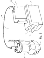
- das Grundgerät der Fig. 1, jedoch mit einer aufgesetzten coulometrischen Adaptereinheit und beigestellter Titrierzelle,
- Fig. 3
- das Grundgerät mit integrierter coulometrischer Einrichtung sowie mit beigestellter coulometrischer Titrierzelle,
- Fig. 4
- einen Längsschnitt durch das Grundgerät in schematischer Darstellung und
- Fig. 5
- eine Frontansicht des Grundgeräts.
- Fig. 1
- a titration device, on the basic device of which a volumetric metering unit is arranged and a titration vessel provided,
- Fig. 2
- 1, but with an attached coulometric adapter unit and titration cell provided,
- Fig. 3
- the basic device with integrated coulometric device and with the provided coulometric titration cell,
- Fig. 4
- a longitudinal section through the basic device in a schematic representation and
- Fig. 5
- a front view of the basic unit.
Gemäß Fig. 1 weist die Titriervorrichtung 1 ein Grundgerät 2 auf, das mit Bedienelementen 3 und Anzeigeelementen 4 (Display) versehen ist. Über eine externe, nicht dargestellte Tastatur ist ebenfalls eine Bedienung möglich. Im Inneren des Grundgeräts 2 befindet sich u. a. eine Steuereinrichtung 22 und eine Betätigungseinrichtung 21, die der volumetrischen Zumessung eines Reagenzes zum Zwecke der Bestimmung einer chemischen Substanz dienen. In Figur 5 sind die Steuereinrichtung 22 und die Betätigungseinrichtung 21 schematisch angedeutet.1, the
Auf dem Grundgerät 2 ist eine Wechseleinheit, die als eine volumetrische Dosiereinheit 16 ausgebildet ist, lösbar befestigt. Das Befestigen kann vorzugsweise dadurch erfolgen, daß die volumetrische Dosiereinheit 16 auf die Oberseite des Grundgerätes 2 aufgesetzt wird. Zur Führung weist die Oberseite des Grundgeräts 2 einen eine Aufnahme 24 bildenden Sockel 35 auf, auf den die Dosiereinheit 16 mit einer entsprechenden Aussparung von vorn nach hinten aufgeschoben und dort verrastet wird. Mittels einer Schnittstelleneinrichtung, die sich auf der Oberseite des Grundgerätes 2 befindet, werden Informationen von der volumetrischen Dosiereinheit 16 abgefragt. Die Dosiereinheit 16 weist hierzu an ihrer Unterseite die notwendigen Kennzeichnungselemente auf. Diese können aus Kodierungsmagneten bestehen, die das maximale Dosiervolumen an das Grundgerät 2 melden (z.B. 5 ml, 20 ml, 50 ml). Weiterhin kann als Kennzeichnungselement ein Schalter vorgesehen sein, der sich in einer Rastvertiefung 36 am Sockel 35 befindet. Ferner erfolgt eine mechanische Kupplung einer der Reagenz-Zumessung dienenden Kolben/Zylinder-Einheit 7 der volumetrischen Dosiereinheit 16 mit der sich im Inneren des Grundgerätes 2 befindlichen Betätigungseinrichtung 21. Diese ist als Kolbenantrieb ausgebildet, der über eine Gewindespindel den Kolben der Kolben/Zylinder-Einheit 7 antreibt. Der Kolbenantrieb wird von Steuerimpulsen der Steuereinrichtung 22 angesteuert. Für die Verbindung des Kolbenantriebs mit dem Kolben sind geeignete mechanische Kupplungselemente 37 vorgesehen, die beim Aufsetzen der Dosiereinheit 16 auf das Grundgerät 2 selbsttätig kuppeln. Wie aus den Figuren 3, 4 und 5 ersichtlich, besteht das dem Grundgerät 2 angehörende Kupplungselement 37 aus einem Antriebswellenende 38, das von der Betätigungseinrichtung 21 angetrieben wird und mittels einer Ausnehmung 39 auf den halben Durchmesser abgestuft ist. Dort befindet sich ein Querstift 40. Die Dosiereinheit 16 weist ein entsprechendes Gegenstück auf, das mit einem Loch zur Aufnahme des Querstiftes 40 versehen ist.An exchange unit, which is designed as a
Die volumetrische Dosiereinheit 16 weist ferner eine Aufnahme 8 für ein das entsprechende Reagenz beinhaltendes Behältnis 9 auf.The
Neben dem Grundgerät 2 befindet sich eine Rührvorrichtung, die als separater Rührer 6 ausgebildet ist. Über eine gemeinsame Bodenplatte können Rührer 6 und Grundgerät 2 -nach einem nicht dargestellten Ausführungsbeispiel- auch miteinander verbunden sein. Auf dem Rührer 6 wird ein die zu untersuchende Probe aufnehmendes Titriergefäß 11 abgestellt. Das Reagenz wird über eine geeignete Schlauchleitung zugeführt. Im Innern des Titriergefäßes 11 befindet sich ein magnetisches Rührelement, daß vom Rührer 6 durch magnetische Kupplung antreibbar ist.In addition to the
Vorzugsweise können dem Grundgerät 2 nacheinander verschiedene volumetrische Dosiereinheiten zugeordnet werden, die sich in der Zumeßmenge der Reagenzien und/oder in der Art des in die Aufnahme 8 eingesetzten Reagenzbehältnisses unterscheiden. Je nach Einsatzgebiet ist die gewünschte volumetrische Dosiereinheit 16 aus einem Wechseleinheitensatz auszuwählen und am Grundgerät 2 zu befestigen.Different volumetric dosing units can preferably be assigned to the
Das Ausführungsbeispiel der Fig. 2 zeigt das gleiche Grundgerät 2, das -gemäß Fig. 1- für die volumetrische Bestimmungsmethode geeignet ist. Im Gegensatz zum Ausführungsbeispiel der Fig. 1 ist jedoch anstelle der volumetrischen Dosiereinheit 16, eine coulometrische Adaptereinheit 18 auf dem Grundgerät 2 lösbar befestigt. Diese Adaptereinheit 18 ist ebenfalls als Wechseleinheit 23 ausgebildet. Die coulometrische Dosiereinheit 18 weist eine Schnittstelle 27 auf, von der elektrische Verbindungen 28 zu sich innerhalb einer Titrierzelle 17 befindlichen Generator-Elektroden führen. Beim Aufsetzen und Verrasten der coulometrischen Adaptereinheit 18 auf dem Grundgerät 2 werden über geeignete Schnittstellenelemente (Anschlüsse - Gegenanschlüsse) die erforderlichen Verbindungswege selbsttätig hergestellt. Zusätzlich können elektrische Verbindungen über ein an der Rückseiten des Grundgeräts 2 sowie der coulometrischen Adaptereinheit 18 mittels Steckanschlüsse anschließbares Kabel hergestellt werden. Die Steuereinrichtung 22, die -im Ausführungsbeispiel der Fig. 1- den Antrieb der Kolben/Zylinder-Einheit 7 ansteuerte, dient beim Ausführungsbeispiel der Fig. 2 ebenfalls der Reagenzzumessung, indem sie einem im Inneren der Adaptereinheit 18 befindlichen Stromgenerator ihre Steuerimpulse zuführt, die zur Stromabgabe des Stromgenerators führt. Dieser Strom wird den Elektroden der Titrierzelle 17 zugeführt, die sich auf einem Rührer 41 befindet.The exemplary embodiment in FIG. 2 shows the same
Die Fig. 3 zeigt ein weiteres Ausführungsbeispiel der erfindungsgemäßen Titriervorrichtung 1. Auf das Grundgerät 2 ist keine Titriereinheit aufgeschoben. Im Unterschied zu dem in Fig. 1 und Fig. 2 gezeigten Grundgerät 2 ist hier die für die Coulometrie erforderliche Einrichtung im Grundgerät 2 enthalten. So befindet sich beispielsweise der für die Erzeugung der Stromimpulse erforderliche Stromgenerator im Innern des Grundgerätes 2. Er wird von der Steuereinrichtung 22 -die sich ebenfalls im Grundgerät 2 befindet- angesteuert. Über eine Schnittstellenvorrichtung 29 -vorzugsweise an der Rückseite des Grundgerätes 2- werden mittels geeigneter Verbindungen 28 der Anschluß (u. a. der Generator-Elektroden) zur coulometrischen Titrierzelle 17 hergestellt, die sich auf einem separaten Rührer 41 befindet. Bei dem Grundgerät 2 des Ausführungsbeispiels der Fig. 3 handelt es sich -mit Ausnahme der für die Coulometrie integrierten Einrichtungen- um dasselbe, was bereits in der Fig. 1 beschrieben wurde. Dies bedeutet, daß auf der Oberseite auch eine volumetrische Dosiereinheit 16 aufsetzbar ist, so daß gleichzeitig oder nacheinander sowohl eine coulometrische Messung als auch eine volumetrische Messung möglich ist. Auf der Oberseite des Grundgeräts 2 befindet sich dafür das entsprechende Kupplungselement 37 für die Kolben/Zylinder-Einheit.3 shows a further exemplary embodiment of the
Sowohl für den abwechselnden wie gleichzeitigen Betrieb der volumetrischen und coulometrischen Anordnung ist vorgesehen, die kompletten Titrierzellen inklusive. Rührer, Elektroden und aller Steckverbindungen gleichzeitig zur Verfügung zu stellen. Damit werden Umbau- beziehungsweise Umsteckarbeiten beim Wechsel der Dosierart vermieden. Darüber hinaus ist es möglich, daß beide Dosierarten in einer gemeinsamen Zelle abwechselnd betrieben werden.The complete titration cells are included for the alternating and simultaneous operation of the volumetric and coulometric arrangement. Provide stirrers, electrodes and all plug connections at the same time. This avoids the need to convert or change the position when changing the metering type. In addition, it is possible for both types of metering to be operated alternately in a common cell.
Abschließend sei darauf hingewiesen, daß die Beschreibung und die Figuren nur auf die für die Erfindung notwendigen Elemente eingeht: Weitere technische Einrichtungen, die für die Titration notwendig, jedoch für die Beschreibung der Erfindung nicht wesentlich sind, wurden -der Übersichtlichkeit halber- weggelassen.In conclusion, it should be pointed out that the description and the figures deal only with the elements necessary for the invention: Further technical devices which are necessary for the titration but are not essential for the description of the invention have been omitted for the sake of clarity.
Claims (10)
Priority Applications (6)
| Application Number | Priority Date | Filing Date | Title |
|---|---|---|---|
| EP93105733A EP0619491B1 (en) | 1993-04-07 | 1993-04-07 | Combined titration apparatus |
| DE59308722T DE59308722D1 (en) | 1993-04-07 | 1993-04-07 | Combined titration device |
| AT93105733T ATE167935T1 (en) | 1993-04-07 | 1993-04-07 | COMBINED TITRATION DEVICE |
| JP5161764A JPH06308113A (en) | 1993-04-07 | 1993-06-30 | Combination type titration device |
| CA002100904A CA2100904A1 (en) | 1993-04-07 | 1993-07-20 | Combined titration device |
| US08/095,120 US5296193A (en) | 1993-04-07 | 1993-07-20 | Combined titration apparatus |
Applications Claiming Priority (1)
| Application Number | Priority Date | Filing Date | Title |
|---|---|---|---|
| EP93105733A EP0619491B1 (en) | 1993-04-07 | 1993-04-07 | Combined titration apparatus |
Publications (2)
| Publication Number | Publication Date |
|---|---|
| EP0619491A1 true EP0619491A1 (en) | 1994-10-12 |
| EP0619491B1 EP0619491B1 (en) | 1998-07-01 |
Family
ID=8212790
Family Applications (1)
| Application Number | Title | Priority Date | Filing Date |
|---|---|---|---|
| EP93105733A Expired - Lifetime EP0619491B1 (en) | 1993-04-07 | 1993-04-07 | Combined titration apparatus |
Country Status (6)
| Country | Link |
|---|---|
| US (1) | US5296193A (en) |
| EP (1) | EP0619491B1 (en) |
| JP (1) | JPH06308113A (en) |
| AT (1) | ATE167935T1 (en) |
| CA (1) | CA2100904A1 (en) |
| DE (1) | DE59308722D1 (en) |
Cited By (1)
| Publication number | Priority date | Publication date | Assignee | Title |
|---|---|---|---|---|
| WO2007012508A1 (en) * | 2005-07-29 | 2007-02-01 | Mettler-Toledo Ag | Titration system |
Families Citing this family (10)
| Publication number | Priority date | Publication date | Assignee | Title |
|---|---|---|---|---|
| USD417634S (en) * | 1998-01-30 | 1999-12-14 | Mettler-Tolodo GmbH | Titrating device |
| FR2784606B1 (en) * | 1998-10-15 | 2000-12-08 | Radiometer Analytical Sa | ACCESSORY FOR MEASUREMENT OR DOSAGE, IN PARTICULAR ELECTROCHEMICAL MEASUREMENT SENSOR |
| US20020137219A1 (en) * | 2001-01-19 | 2002-09-26 | Owens Robert Austin | Titration method for aqueous base developer solution |
| WO2002063292A1 (en) * | 2001-02-05 | 2002-08-15 | The University Of Wyoming Research Corporation | Automated flocculation titrimeter system |
| US20070041871A1 (en) * | 2005-08-16 | 2007-02-22 | Frank Lecrone | Gravimetric field titration kit and method of using thereof |
| US8858769B2 (en) | 2011-02-18 | 2014-10-14 | Kyoto Electronics Manufacturing Co., Ltd. | Karl fischer titrator and karl fischer titration method |
| CN102445555A (en) * | 2011-09-21 | 2012-05-09 | 中国科学技术大学 | Anaerobic reactor liquid phase parameter monitoring device and method thereof |
| KR101870050B1 (en) * | 2016-12-22 | 2018-06-21 | 가천대학교 산학협력단 | Method Of Measuring Boron Concentrations And Apparatus Using The Same |
| CN109144122A (en) * | 2018-06-29 | 2019-01-04 | 南京高速齿轮制造有限公司 | The device of on-line automatic prosecution acid base concentration in etch assembly line |
| US11717202B2 (en) | 2019-04-10 | 2023-08-08 | Foothold Labs Inc. | Mobile lab-on-a-chip diagnostic system |
Citations (4)
| Publication number | Priority date | Publication date | Assignee | Title |
|---|---|---|---|---|
| FR1554684A (en) * | 1967-09-08 | 1969-01-24 | ||
| CH534877A (en) * | 1972-02-01 | 1973-03-15 | Mettler Instrumente Ag | Process for automatic titration and device for carrying out the process |
| FR2354562A1 (en) * | 1976-06-09 | 1978-01-06 | Mettler Instrumente Ag | TITRATION DEVICE |
| DE9003629U1 (en) * | 1989-04-04 | 1990-06-13 | Mettler-Toledo Ag, Greifensee, Ch |
Family Cites Families (2)
| Publication number | Priority date | Publication date | Assignee | Title |
|---|---|---|---|---|
| US4244800A (en) * | 1979-08-23 | 1981-01-13 | The United States Of America As Represented By The United States Department Of Energy | Apparatus for use in rapid and accurate controlled-potential coulometric analysis |
| IL82131A0 (en) * | 1987-04-07 | 1987-10-30 | Univ Ramot | Coulometric assay system |
-
1993
- 1993-04-07 AT AT93105733T patent/ATE167935T1/en not_active IP Right Cessation
- 1993-04-07 EP EP93105733A patent/EP0619491B1/en not_active Expired - Lifetime
- 1993-04-07 DE DE59308722T patent/DE59308722D1/en not_active Expired - Fee Related
- 1993-06-30 JP JP5161764A patent/JPH06308113A/en active Pending
- 1993-07-20 US US08/095,120 patent/US5296193A/en not_active Expired - Fee Related
- 1993-07-20 CA CA002100904A patent/CA2100904A1/en not_active Abandoned
Patent Citations (4)
| Publication number | Priority date | Publication date | Assignee | Title |
|---|---|---|---|---|
| FR1554684A (en) * | 1967-09-08 | 1969-01-24 | ||
| CH534877A (en) * | 1972-02-01 | 1973-03-15 | Mettler Instrumente Ag | Process for automatic titration and device for carrying out the process |
| FR2354562A1 (en) * | 1976-06-09 | 1978-01-06 | Mettler Instrumente Ag | TITRATION DEVICE |
| DE9003629U1 (en) * | 1989-04-04 | 1990-06-13 | Mettler-Toledo Ag, Greifensee, Ch |
Cited By (1)
| Publication number | Priority date | Publication date | Assignee | Title |
|---|---|---|---|---|
| WO2007012508A1 (en) * | 2005-07-29 | 2007-02-01 | Mettler-Toledo Ag | Titration system |
Also Published As
| Publication number | Publication date |
|---|---|
| CA2100904A1 (en) | 1994-10-08 |
| US5296193A (en) | 1994-03-22 |
| JPH06308113A (en) | 1994-11-04 |
| EP0619491B1 (en) | 1998-07-01 |
| DE59308722D1 (en) | 1998-08-06 |
| ATE167935T1 (en) | 1998-07-15 |
Similar Documents
| Publication | Publication Date | Title |
|---|---|---|
| DE2402166C3 (en) | Arrangement for the automatic analysis of liquid samples | |
| DE69737052T2 (en) | Automated device for performing biochemical analyzes | |
| DE4310808C2 (en) | Liquid dosing system | |
| DE2804881A1 (en) | EVALUATION DEVICE FOR THE AUTOMATIC PHOTOMETRIC ANALYSIS OF LIQUID SAMPLES | |
| DE2842241A1 (en) | DILUTION / DISTRIBUTION DEVICE AND METHOD FOR DETERMINING THE SUCTION OF A PRE-DETERMINED VOLUME OF LIQUID IN SUCH DILUTION / DISTRIBUTION DEVICE | |
| EP0619491B1 (en) | Combined titration apparatus | |
| DE102008050092A1 (en) | Mobile water analysis arrangement | |
| EP0152610A2 (en) | Analysis method and rack for carrying out the method | |
| DE69925210T2 (en) | Tip for a suction device | |
| DE3641593A1 (en) | DOUBLE PIPETTE DEVICE | |
| DE3504955A1 (en) | AUTOMATIC CHEMICAL ANALYZER | |
| WO1992005449A1 (en) | Device for the simultaneous measurement of various physical and chemical parameters of a liquid | |
| DE1816226C3 (en) | Reaction vessel | |
| EP1240944A2 (en) | Assay system for biological samples | |
| DE2610808B2 (en) | REACTION DEVICE FOR AN AUTOMATIC ANALYZER | |
| DE2540969A1 (en) | AUTOMATIC SAMPLE PREPARATION DEVICE | |
| DE2436984C3 (en) | Device for the quantitative determination of the alcohol content of the human breath | |
| DE3913632C2 (en) | Titration device | |
| DE3335641A1 (en) | THINNING PIPETTING DEVICE | |
| DE2308881C2 (en) | Apparatus and method for measuring the carbon dioxide content in a blood sample | |
| DE3623052A1 (en) | Fluorescence analyser | |
| DE3807414C2 (en) | ||
| DE3844105A1 (en) | TEST CARRIER ANALYSIS SYSTEM | |
| DE2445409C3 (en) | Multiple application device for the preparation and application of a large number of electrophoresis analysis samples | |
| DE3151807A1 (en) | PROBE FOR A SYSTEM FOR COULOMETRICALLY MEASURING THE THICKNESS OF A METAL LAYER |
Legal Events
| Date | Code | Title | Description |
|---|---|---|---|
| PUAI | Public reference made under article 153(3) epc to a published international application that has entered the european phase |
Free format text: ORIGINAL CODE: 0009012 |
|
| 17P | Request for examination filed |
Effective date: 19931007 |
|
| AK | Designated contracting states |
Kind code of ref document: A1 Designated state(s): AT BE CH DE DK ES FR GB GR IE IT LI LU MC NL PT SE |
|
| 17Q | First examination report despatched |
Effective date: 19960409 |
|
| GRAG | Despatch of communication of intention to grant |
Free format text: ORIGINAL CODE: EPIDOS AGRA |
|
| GRAG | Despatch of communication of intention to grant |
Free format text: ORIGINAL CODE: EPIDOS AGRA |
|
| GRAH | Despatch of communication of intention to grant a patent |
Free format text: ORIGINAL CODE: EPIDOS IGRA |
|
| GRAH | Despatch of communication of intention to grant a patent |
Free format text: ORIGINAL CODE: EPIDOS IGRA |
|
| GRAA | (expected) grant |
Free format text: ORIGINAL CODE: 0009210 |
|
| AK | Designated contracting states |
Kind code of ref document: B1 Designated state(s): AT BE CH DE DK ES FR GB GR IE IT LI LU MC NL PT SE |
|
| PG25 | Lapsed in a contracting state [announced via postgrant information from national office to epo] |
Ref country code: NL Free format text: LAPSE BECAUSE OF FAILURE TO SUBMIT A TRANSLATION OF THE DESCRIPTION OR TO PAY THE FEE WITHIN THE PRESCRIBED TIME-LIMIT Effective date: 19980701 Ref country code: IT Free format text: LAPSE BECAUSE OF FAILURE TO SUBMIT A TRANSLATION OF THE DESCRIPTION OR TO PAY THE FEE WITHIN THE PRESCRIBED TIME-LIMIT;WARNING: LAPSES OF ITALIAN PATENTS WITH EFFECTIVE DATE BEFORE 2007 MAY HAVE OCCURRED AT ANY TIME BEFORE 2007. THE CORRECT EFFECTIVE DATE MAY BE DIFFERENT FROM THE ONE RECORDED. Effective date: 19980701 Ref country code: GR Free format text: LAPSE BECAUSE OF NON-PAYMENT OF DUE FEES Effective date: 19980701 Ref country code: GB Free format text: LAPSE BECAUSE OF FAILURE TO SUBMIT A TRANSLATION OF THE DESCRIPTION OR TO PAY THE FEE WITHIN THE PRESCRIBED TIME-LIMIT Effective date: 19980701 Ref country code: FR Free format text: LAPSE BECAUSE OF FAILURE TO SUBMIT A TRANSLATION OF THE DESCRIPTION OR TO PAY THE FEE WITHIN THE PRESCRIBED TIME-LIMIT Effective date: 19980701 Ref country code: ES Free format text: THE PATENT HAS BEEN ANNULLED BY A DECISION OF A NATIONAL AUTHORITY Effective date: 19980701 |
|
| REF | Corresponds to: |
Ref document number: 167935 Country of ref document: AT Date of ref document: 19980715 Kind code of ref document: T |
|
| REG | Reference to a national code |
Ref country code: CH Ref legal event code: EP |
|
| REF | Corresponds to: |
Ref document number: 59308722 Country of ref document: DE Date of ref document: 19980806 |
|
| PG25 | Lapsed in a contracting state [announced via postgrant information from national office to epo] |
Ref country code: SE Free format text: LAPSE BECAUSE OF FAILURE TO SUBMIT A TRANSLATION OF THE DESCRIPTION OR TO PAY THE FEE WITHIN THE PRESCRIBED TIME-LIMIT Effective date: 19981001 Ref country code: PT Free format text: LAPSE BECAUSE OF FAILURE TO SUBMIT A TRANSLATION OF THE DESCRIPTION OR TO PAY THE FEE WITHIN THE PRESCRIBED TIME-LIMIT Effective date: 19981001 Ref country code: DK Free format text: LAPSE BECAUSE OF FAILURE TO SUBMIT A TRANSLATION OF THE DESCRIPTION OR TO PAY THE FEE WITHIN THE PRESCRIBED TIME-LIMIT Effective date: 19981001 |
|
| REG | Reference to a national code |
Ref country code: IE Ref legal event code: FG4D Free format text: GERMAN |
|
| EN | Fr: translation not filed | ||
| NLV1 | Nl: lapsed or annulled due to failure to fulfill the requirements of art. 29p and 29m of the patents act | ||
| GBV | Gb: ep patent (uk) treated as always having been void in accordance with gb section 77(7)/1977 [no translation filed] |
Effective date: 19980701 |
|
| PG25 | Lapsed in a contracting state [announced via postgrant information from national office to epo] |
Ref country code: IE Free format text: LAPSE BECAUSE OF NON-PAYMENT OF DUE FEES Effective date: 19990219 |
|
| REG | Reference to a national code |
Ref country code: IE Ref legal event code: FD4D |
|
| PG25 | Lapsed in a contracting state [announced via postgrant information from national office to epo] |
Ref country code: LU Free format text: LAPSE BECAUSE OF NON-PAYMENT OF DUE FEES Effective date: 19990407 Ref country code: AT Free format text: LAPSE BECAUSE OF NON-PAYMENT OF DUE FEES Effective date: 19990407 |
|
| PG25 | Lapsed in a contracting state [announced via postgrant information from national office to epo] |
Ref country code: LI Free format text: LAPSE BECAUSE OF NON-PAYMENT OF DUE FEES Effective date: 19990430 Ref country code: CH Free format text: LAPSE BECAUSE OF NON-PAYMENT OF DUE FEES Effective date: 19990430 Ref country code: BE Free format text: LAPSE BECAUSE OF NON-PAYMENT OF DUE FEES Effective date: 19990430 |
|
| PLBE | No opposition filed within time limit |
Free format text: ORIGINAL CODE: 0009261 |
|
| STAA | Information on the status of an ep patent application or granted ep patent |
Free format text: STATUS: NO OPPOSITION FILED WITHIN TIME LIMIT |
|
| 26N | No opposition filed | ||
| BERE | Be: lapsed |
Owner name: DEUTSCHE METROHM G.M.B.H. & CO. ELEKTRONISCHE MES Effective date: 19990430 |
|
| PG25 | Lapsed in a contracting state [announced via postgrant information from national office to epo] |
Ref country code: MC Free format text: LAPSE BECAUSE OF NON-PAYMENT OF DUE FEES Effective date: 19991031 |
|
| REG | Reference to a national code |
Ref country code: CH Ref legal event code: PL |
|
| PGFP | Annual fee paid to national office [announced via postgrant information from national office to epo] |
Ref country code: DE Payment date: 20030502 Year of fee payment: 11 |
|
| PG25 | Lapsed in a contracting state [announced via postgrant information from national office to epo] |
Ref country code: DE Free format text: LAPSE BECAUSE OF NON-PAYMENT OF DUE FEES Effective date: 20041103 |