EP0618413A1 - Method and apparatus for prechilling tap water in ice machines - Google Patents
Method and apparatus for prechilling tap water in ice machines Download PDFInfo
- Publication number
- EP0618413A1 EP0618413A1 EP94104931A EP94104931A EP0618413A1 EP 0618413 A1 EP0618413 A1 EP 0618413A1 EP 94104931 A EP94104931 A EP 94104931A EP 94104931 A EP94104931 A EP 94104931A EP 0618413 A1 EP0618413 A1 EP 0618413A1
- Authority
- EP
- European Patent Office
- Prior art keywords
- tap water
- straight tube
- tubing
- waste water
- coil
- Prior art date
- Legal status (The legal status is an assumption and is not a legal conclusion. Google has not performed a legal analysis and makes no representation as to the accuracy of the status listed.)
- Granted
Links
- 239000008399 tap water Substances 0.000 title claims abstract description 60
- 235000020679 tap water Nutrition 0.000 title claims abstract description 60
- 238000000034 method Methods 0.000 title claims abstract description 8
- 239000002351 wastewater Substances 0.000 claims abstract description 42
- RYGMFSIKBFXOCR-UHFFFAOYSA-N Copper Chemical compound [Cu] RYGMFSIKBFXOCR-UHFFFAOYSA-N 0.000 claims abstract description 17
- 229910052802 copper Inorganic materials 0.000 claims abstract description 17
- 239000010949 copper Substances 0.000 claims abstract description 17
- 230000008878 coupling Effects 0.000 claims description 9
- 238000010168 coupling process Methods 0.000 claims description 9
- 238000005859 coupling reaction Methods 0.000 claims description 9
- 230000003247 decreasing effect Effects 0.000 claims description 3
- 238000007710 freezing Methods 0.000 claims description 3
- 230000008014 freezing Effects 0.000 claims description 3
- 230000008569 process Effects 0.000 abstract description 2
- 239000012530 fluid Substances 0.000 abstract 1
- XLYOFNOQVPJJNP-UHFFFAOYSA-N water Substances O XLYOFNOQVPJJNP-UHFFFAOYSA-N 0.000 description 9
- POIUWJQBRNEFGX-XAMSXPGMSA-N cathelicidin Chemical compound C([C@@H](C(=O)N[C@@H](CCCNC(N)=N)C(=O)N[C@@H](CCCCN)C(=O)N[C@@H](CO)C(=O)N[C@@H](CCCCN)C(=O)N[C@@H](CCC(O)=O)C(=O)N[C@@H](CCCCN)C(=O)N[C@@H]([C@@H](C)CC)C(=O)NCC(=O)N[C@@H](CCCCN)C(=O)N[C@@H](CCC(O)=O)C(=O)N[C@@H](CC=1C=CC=CC=1)C(=O)N[C@@H](CCCCN)C(=O)N[C@@H](CCCNC(N)=N)C(=O)N[C@@H]([C@@H](C)CC)C(=O)N[C@@H](C(C)C)C(=O)N[C@@H](CCC(N)=O)C(=O)N[C@@H](CCCNC(N)=N)C(=O)N[C@@H]([C@@H](C)CC)C(=O)N[C@@H](CCCCN)C(=O)N[C@@H](CC(O)=O)C(=O)N[C@@H](CC=1C=CC=CC=1)C(=O)N[C@@H](CC(C)C)C(=O)N[C@@H](CCCNC(N)=N)C(=O)N[C@@H](CC(N)=O)C(=O)N[C@@H](CC(C)C)C(=O)N[C@@H](C(C)C)C(=O)N1[C@@H](CCC1)C(=O)N[C@@H](CCCNC(N)=N)C(=O)N[C@@H]([C@@H](C)O)C(=O)N[C@@H](CCC(O)=O)C(=O)N[C@@H](CO)C(O)=O)NC(=O)[C@H](CC=1C=CC=CC=1)NC(=O)[C@H](CC(O)=O)NC(=O)CNC(=O)[C@H](CC(C)C)NC(=O)[C@@H](N)CC(C)C)C1=CC=CC=C1 POIUWJQBRNEFGX-XAMSXPGMSA-N 0.000 description 3
- 235000020188 drinking water Nutrition 0.000 description 3
- 239000003651 drinking water Substances 0.000 description 3
- 238000005057 refrigeration Methods 0.000 description 3
- 238000009825 accumulation Methods 0.000 description 2
- 238000001816 cooling Methods 0.000 description 2
- 238000003306 harvesting Methods 0.000 description 2
- 229910052500 inorganic mineral Inorganic materials 0.000 description 2
- 238000009434 installation Methods 0.000 description 2
- 239000011707 mineral Substances 0.000 description 2
- 239000013049 sediment Substances 0.000 description 2
- 239000002470 thermal conductor Substances 0.000 description 2
- 230000004075 alteration Effects 0.000 description 1
- 239000012080 ambient air Substances 0.000 description 1
- 239000006227 byproduct Substances 0.000 description 1
- 230000008859 change Effects 0.000 description 1
- 230000007423 decrease Effects 0.000 description 1
- 238000007599 discharging Methods 0.000 description 1
- 230000035622 drinking Effects 0.000 description 1
- 238000009413 insulation Methods 0.000 description 1
- 239000007788 liquid Substances 0.000 description 1
- 238000012423 maintenance Methods 0.000 description 1
- 238000004519 manufacturing process Methods 0.000 description 1
- 239000000463 material Substances 0.000 description 1
- 230000000750 progressive effect Effects 0.000 description 1
Images
Classifications
-
- F—MECHANICAL ENGINEERING; LIGHTING; HEATING; WEAPONS; BLASTING
- F25—REFRIGERATION OR COOLING; COMBINED HEATING AND REFRIGERATION SYSTEMS; HEAT PUMP SYSTEMS; MANUFACTURE OR STORAGE OF ICE; LIQUEFACTION SOLIDIFICATION OF GASES
- F25C—PRODUCING, WORKING OR HANDLING ICE
- F25C1/00—Producing ice
-
- F—MECHANICAL ENGINEERING; LIGHTING; HEATING; WEAPONS; BLASTING
- F28—HEAT EXCHANGE IN GENERAL
- F28D—HEAT-EXCHANGE APPARATUS, NOT PROVIDED FOR IN ANOTHER SUBCLASS, IN WHICH THE HEAT-EXCHANGE MEDIA DO NOT COME INTO DIRECT CONTACT
- F28D7/00—Heat-exchange apparatus having stationary tubular conduit assemblies for both heat-exchange media, the media being in contact with different sides of a conduit wall
- F28D7/02—Heat-exchange apparatus having stationary tubular conduit assemblies for both heat-exchange media, the media being in contact with different sides of a conduit wall the conduits being helically coiled
- F28D7/024—Heat-exchange apparatus having stationary tubular conduit assemblies for both heat-exchange media, the media being in contact with different sides of a conduit wall the conduits being helically coiled the conduits of only one medium being helically coiled tubes, the coils having a cylindrical configuration
Definitions
- This invention relates generally to a method and apparatus for prechilling the warm drinking (tap) water, fed into an ice maker machine to make ice cubes and the like, with the near freezing waste water ejected by the machine.
- Ice making machines ace now widely used, especially in warm climates. They consume considerable energy some of which is unnecessarily and needlessly wasted.
- U.S. patent 4,338,794 shows an ice maker which prechills the tap water as well as the freon using two copper coils within two chambers of a casing.
- the tap water flows through one coil in one chamber, and the freon flows in the other coil in an adjacent chamber.
- Cold waste water flows through both chambers.
- U.S. patent 2,403,272 shows a water cooler having a refrigeration system using freon, a compressor and evaporator for cooling drinking water.
- the evaporator consists of a tank 1 in which a first coil 9 surrounds a second coil 8.
- Coil 8 is inside a pipe 11 whose bottom end opens to the interior of tank 1 and whose top end has a cold water outlet 4.
- the tap water fills tank 1 and pipe 11.
- freon flows under pressure through coils 8, 9, it changes from liquid to vapor but remains at the same cold temperature throughout this phase change and prechills the drinking water in tank 1 and in pipe 11. Should a leak occur in the freon piping, the freon will escape therefrom and contaminate the drinking water.
- the other prechiller has a reservoir in a casing containing a heat exchanger in the form of a straight copper pipe.
- the casing has an inlet for receiving the relatively warm tap water, another inlet for receiving the ejected cold waste water from the machine, an outlet for discharging the prechilled tap water, and an overflow tube through which the excess waste water from the reservoir can escape.
- the waste water warms up due to the transfer of heat from the tap water flowing in the straight pipe. As a result, the tap water's temperature flowing through the straight copper pipe decreases.
- prechilling the tap water with the cold waste water from an ice machine is achieved by using an insulated, elongated casing having a top cap.
- the casing encloses a reservoir housing a heat exchanger made of a relatively long tubing of copper or the like to provide a relatively long path of travel for the tap water.
- the heat exchanger is in the form of a coil followed by a substantially straight tube within and surrounded by the coil's turns.
- a hollow member, closed at one end, is spaced from the straight tubing. The coils turns surround the hollow member and the straight tubing.
- the hollow member is heat-insulating and is mounted over and is spaced from the straight tubing to form there between an elongated chamber.
- the tap water flows downwardly in the coil toward the lowest one of the turns, and upwardly through the straight tube to the ice maker.
- the cold waste water flows through the elongated chamber into the reservoir and exits through an overflow outlet, thereby progressively and continuously increasing the temperature of the waste water and correspondingly decreasing the tap water's temperature.
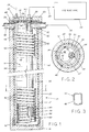
- the prechiller 10 of this invention has an elongated casing 12, preferably upright, which encloses a reservoir 14.
- Casing 12 can be a cylindrical pipe section having a bottom cap 16 and a top cap 18. It is entirely covered with a layer of thermal insulation 20.
- Top cap 18 has a bulkhead connector 22 for receiving tap water from line 24, and a bulkhead connector 26 through which the prechilled tap water flows out into line 28 of an ice machine 30, such as an ice cube maker used in restaurants, bars, hotels, schools, hospitals, etc.
- the side wall of top cap 18 has a socket 32 that receives from machine 30 ice cold waste water 54 on line 34, and a socket 36 which allows excess waste water 54 to escape to drain line 38.
- a heat exchanger 40 having a first stage 42 and a second stage 44, both sharing a single continuous tubing 46 of great length compared to the length of casing 12.
- Tubing 46 is made of a good thermal conductor preferably copper.
- the inlet end 48 of tubing 46 is removably coupled to connector 22, and the outlet end 49 of tubing 46 is removably coupled to connector 26.
- Tubing 46 in stage 42 is wound into a coil 50 having spiral turns 52 that are near to the inner wall of casing 12 (FIG.2), thereby substantially increasing the length of the path of travel for the tap water within the casing.
- the tube's sectional area is purposely altered from circular to substantially rectangular or oval (FIG. 3). It is believed that such an alteration favorably alters the flow and heat exchange dynamics, i.e., the heat exchange surface area relative to the volume of tap water contained within tubing 46.
- tubing 46 in second heat exchanger stage 44 is substantially straight and upright and will hereinafter be also designated by the numeral 44.
- Straight tube 44 is inside of and completely surrounded by turns 52.
- the bottom end of tube 44 merges smoothly with the lowest turn 52'.
- tube 44 is surrounded by a concentric upright conduit 58, having an open end 59 and a closed off top end 60.
- Conduit 58 is made of a poor thermal conductor material.
- tube 44 is outside of and parallel to conduit 58.
- the space between tube 44 and the inner wall of conduit 58 forms an elongated chamber 64 for receiving waste water 54 from line 34 through socket 32 and a coupling 62.
- chamber 64 receives ice cold waste water 54 which flows downwardly through chamber 64, along and around straight tube 44, through open bottom end 59 of chamber 64, which is also the bottom of reservoir 14, and upwardly towards the top of reservoir 14, and along and around the coil's turns 52.
- Conduit 58 thermally isolates the colder waste water 54 in chamber 64 from the warmer waste water 54 within the rest of reservoir 14.
- the inlet 48 of tubing 46 receives from line 24 tap water under pressure which circulates downwardly through turns 52.
- the tap water flows spirally toward the lowest turn 52', thence upwardly within straight tube 44, and through its tap water outlet 49 into feed line 28 of machine 30 for making ice.
- the waste water 54 in reservoir 14 cools the downwardly circulating tap water to progressively lower temperature levels.
- the same tap water is further cooled to progressively lower temperature levels as it flows upwardly in straight tube 44 from the lowest turn 52' of coil 50, because the arriving counter flowing coldest waste water 54 from machine 30 maximally lowers the temperature of the tap water in tube 44 before it flows out through outlet 49 into feed line 28.
- the waste water's temperature progressively increases from its top to the bottom of reservoir 14.
- the waste water's temperature progressively increases from its bottom to its top, thereby resulting in a progressive rise in the temperature of the waste water surrounding tubing 46 from inlet socket 32 to to outlet socket 36, whereat it has its highest temperature, while the tap water has its lowest temperature within tube 44 at the level of socket 32.
- the temperature of the tap water within the entire length of tubing 46 is progressively and continuously lowered from its inlet end 48 to its outlet end 49.
- the changes in the temperature in the waste water 54 per unit of vertical height enhances the heat transfer from the tap water flowing through tubing 46 to the surrounding waste water 54, and generates water currents within reservoir 14 which tend to maintain the surfaces of heat exchanger 40 free of sediment accumulation.
- tubing 46 tends to improve the amount of heat transferred in a unit of time across a unit of surface area of heat exchanger 40, and in a unit of length of tubing 46.
- the heat exchanger's first stage 42 first prechills the fresh tap water with warmed up waste water received from second stage 44, and second stage 44 further prechills the top water received from first stage 42 with fresh ice cold waste water received from line 34 into chamber 64.
- the cooling energy within the waste water discharged from ice machine 30, which would otherwise be wasted, is optimally reclaimed by heat exchanger 40 which removes heat energy from the tap water prior to injecting it into the ice making section of machine 30.
- Prechiller 10 is effective, efficient and compact. Using it with an ice machine will reduce the heat produced by the machine. Less "wear and tear" will be experienced by the machine's s active parts. There will be less time for mineral buildup on its freeze plate, and its bin will fill up faster with ice during peak demands. It will produce more ice in the same amount of time, or the same amount of ice in a shorter time.
- the preferred embodiment for optimum thermal efficiency and adapted for use in most ice maker installations utilized refrigeration grade copper tubing having a 3/8 inch outside diameter (OD) and a wall thickness of .035 inch.
- Casing (12) had a 4 inch OD, a height of 26 inch, and a reservoir (12) whose volume is 1.44 gallon.
- the total length of tubing (46) is 48 feet yielding 54 turns (52), an outside diameter of coil (50) of 3.6 inch, an inside diameter of coil (50) of 2.9 inch, and a length of straight tube (44) of 25.5 inch.
- the coil should use between 4 and 23 feet of copper tubing per linear foot of casing (12).
- the volume of the reservoir (14) with the tubing (46) is about 1.13 gal.
- the present invention may be carried out in various ways and is not limited to the specific way described above, which is at present the best mode contemplated for accomplishing the objectives previously enumerated, as well as other objectives which will become apparent to those skilled in the art.
- the prechiller 10 will function with the casing 12 in an inclined or horizontal position but at a sacrifice in thermal heat exchange efficiency between the warm tap water and the cold waste water.
Landscapes
- Engineering & Computer Science (AREA)
- Physics & Mathematics (AREA)
- Mechanical Engineering (AREA)
- Thermal Sciences (AREA)
- General Engineering & Computer Science (AREA)
- Devices That Are Associated With Refrigeration Equipment (AREA)
- Beverage Vending Machines With Cups, And Gas Or Electricity Vending Machines (AREA)
- Heat-Exchange Devices With Radiators And Conduit Assemblies (AREA)
Abstract
Description
- This invention relates generally to a method and apparatus for prechilling the warm drinking (tap) water, fed into an ice maker machine to make ice cubes and the like, with the near freezing waste water ejected by the machine.
- Ice making machines ace now widely used, especially in warm climates. They consume considerable energy some of which is unnecessarily and needlessly wasted.
- In the U.S.A., ice makers ace certified and rated in accordance with American Refrigeration Institute (ARI) Standard 810-91. Test conditions for standard ratings are 90oF ambient air, 70oF tap water, and about 30 psig water inlet pressure.
- In most ice makers, and as a byproduct of the ice making process, a considerable volume of unused nearly 1oC cold waste water is now being dumped into the sewer, even though it had long been suggested to use this cold waste water for prechilling the tap water flowing into the machine, as will now be described in more detail.
- The lower the tap water's temperature is, the higher will be the output (harvest) of ice from the machine during each cycle of ice production.
- Lowering tap water's temperature by about 10oC can considerably increase the machine's ice output. A drop of 15oC in the summer would be most desirable and would produce benefits including; savings on the amount of required floor space for the ice maker, on its cost and installation, and on its operating and maintenance expenses.
- Workers in this ice making art had striven to arrive at practical water chilling methods and devices.
- U.S. patent 2,775,100, issued on Dec. 25, 1956, very briefly suggests to prechill the tap water with the cold waste water. "As the water is discharged from the tank, it proceeds to a
receiver 40 where it is passed in heat exchange relation with the water being supplied" by pipe 11 (Col. 4, lns. 26-29). - U.S. patent 4,338,794 shows an ice maker which prechills the tap water as well as the freon using two copper coils within two chambers of a casing. The tap water flows through one coil in one chamber, and the freon flows in the other coil in an adjacent chamber. Cold waste water flows through both chambers.
- U.S. patent 2,403,272 shows a water cooler having a refrigeration system using freon, a compressor and evaporator for cooling drinking water. The evaporator consists of a tank 1 in which a first coil 9 surrounds a second coil 8. Coil 8 is inside a pipe 11 whose bottom end opens to the interior of tank 1 and whose top end has a cold water outlet 4. The tap water fills tank 1 and pipe 11. As the freon flows under pressure through coils 8, 9, it changes from liquid to vapor but remains at the same cold temperature throughout this phase change and prechills the drinking water in tank 1 and in pipe 11. Should a leak occur in the freon piping, the freon will escape therefrom and contaminate the drinking water.
- Applicant was told of two tap water prechiller devices that had been introduced to the market. One proposed a copper pipe inside a plastic pipe. The tap water flowed in the copper pipe, and the cold waste water in the annular space between the two pipes. Occlusion of the annular space could be expected due to mineral sediment accumulation. The other prechiller has a reservoir in a casing containing a heat exchanger in the form of a straight copper pipe. The casing has an inlet for receiving the relatively warm tap water, another inlet for receiving the ejected cold waste water from the machine, an outlet for discharging the prechilled tap water, and an overflow tube through which the excess waste water from the reservoir can escape. The waste water warms up due to the transfer of heat from the tap water flowing in the straight pipe. As a result, the tap water's temperature flowing through the straight copper pipe decreases.
- It is a general object of this invention to provide an effective, efficient and compact tap water prechiller, which can be adapted for use on a wide range of ice makers from small to large sizes, and which substantially enhances the amount of heat transferred in a unit of time across a unit of surface area of the copper tubing, thereby optimally lowering the tap water's temperature per unit of casing volume.
- According to the present invention, prechilling the tap water with the cold waste water from an ice machine is achieved by using an insulated, elongated casing having a top cap. The casing encloses a reservoir housing a heat exchanger made of a relatively long tubing of copper or the like to provide a relatively long path of travel for the tap water. The heat exchanger is in the form of a coil followed by a substantially straight tube within and surrounded by the coil's turns. A hollow member, closed at one end, is spaced from the straight tubing. The coils turns surround the hollow member and the straight tubing.
- Preferably, the hollow member is heat-insulating and is mounted over and is spaced from the straight tubing to form there between an elongated chamber. In use, the tap water flows downwardly in the coil toward the lowest one of the turns, and upwardly through the straight tube to the ice maker. The cold waste water flows through the elongated chamber into the reservoir and exits through an overflow outlet, thereby progressively and continuously increasing the temperature of the waste water and correspondingly decreasing the tap water's temperature.
- Specific embodiments of the invention will be described, by way of example only, in connection with the accompanying drawings, wherein:
- FIG. 1 is a longitudinal sectional view of a preferred embodiment of the prechiller of the present invention;
- FIG. 2 is a sectional view of the prechiller taken on line 2-2 of FIG. 1; and
- FIG. 3 is a sectional view on line 3-3 of FIG. 2 of the long tubing from which the heat exchanger is made.
- In its preferred embodiment and with reference to FIGS. 1-2, the
prechiller 10 of this invention has anelongated casing 12, preferably upright, which encloses areservoir 14.Casing 12 can be a cylindrical pipe section having a bottom cap 16 and atop cap 18. It is entirely covered with a layer ofthermal insulation 20. -
Top cap 18 has abulkhead connector 22 for receiving tap water fromline 24, and abulkhead connector 26 through which the prechilled tap water flows out intoline 28 of anice machine 30, such as an ice cube maker used in restaurants, bars, hotels, schools, hospitals, etc. The side wall oftop cap 18 has asocket 32 that receives frommachine 30 icecold waste water 54 online 34, and asocket 36 which allowsexcess waste water 54 to escape todrain line 38. - Within
reservoir 14 is aheat exchanger 40 having afirst stage 42 and asecond stage 44, both sharing a singlecontinuous tubing 46 of great length compared to the length ofcasing 12. Tubing 46 is made of a good thermal conductor preferably copper. - The
inlet end 48 oftubing 46 is removably coupled toconnector 22, and theoutlet end 49 oftubing 46 is removably coupled toconnector 26. -
Tubing 46 instage 42 is wound into acoil 50 having spiral turns 52 that are near to the inner wall of casing 12 (FIG.2), thereby substantially increasing the length of the path of travel for the tap water within the casing. - In such coiling, the tube's sectional area is purposely altered from circular to substantially rectangular or oval (FIG. 3). It is believed that such an alteration favorably alters the flow and heat exchange dynamics, i.e., the heat exchange surface area relative to the volume of tap water contained within
tubing 46. - The portion of
tubing 46 in secondheat exchanger stage 44 is substantially straight and upright and will hereinafter be also designated by thenumeral 44.Straight tube 44 is inside of and completely surrounded byturns 52. The bottom end oftube 44 merges smoothly with the lowest turn 52'. - In the preferred embodiment, along substantially its entire length,
tube 44 is surrounded by a concentricupright conduit 58, having anopen end 59 and a closed offtop end 60.Conduit 58 is made of a poor thermal conductor material. In a less preferred embodiment (not shown),tube 44 is outside of and parallel toconduit 58. - The space between
tube 44 and the inner wall ofconduit 58 forms anelongated chamber 64 for receivingwaste water 54 fromline 34 throughsocket 32 and acoupling 62. - In the first ice harvest cycle, from
line 34 ofice maker 30chamber 64 receives icecold waste water 54 which flows downwardly throughchamber 64, along and aroundstraight tube 44, throughopen bottom end 59 ofchamber 64, which is also the bottom ofreservoir 14, and upwardly towards the top ofreservoir 14, and along and around the coil's turns 52. -
Conduit 58 thermally isolates thecolder waste water 54 inchamber 64 from thewarmer waste water 54 within the rest ofreservoir 14. - The
inlet 48 oftubing 46 receives fromline 24 tap water under pressure which circulates downwardly throughturns 52. The tap water flows spirally toward the lowest turn 52', thence upwardly withinstraight tube 44, and through itstap water outlet 49 intofeed line 28 ofmachine 30 for making ice. - The
waste water 54 inreservoir 14 cools the downwardly circulating tap water to progressively lower temperature levels. - The same tap water is further cooled to progressively lower temperature levels as it flows upwardly in
straight tube 44 from the lowest turn 52' ofcoil 50, because the arriving counter flowingcoldest waste water 54 frommachine 30 maximally lowers the temperature of the tap water intube 44 before it flows out throughoutlet 49 intofeed line 28. - In
chamber 64 the waste water's temperature progressively increases from its top to the bottom ofreservoir 14. Inreservoir 14 the waste water's temperature progressively increases from its bottom to its top, thereby resulting in a progressive rise in the temperature of the wastewater surrounding tubing 46 frominlet socket 32 to tooutlet socket 36, whereat it has its highest temperature, while the tap water has its lowest temperature withintube 44 at the level ofsocket 32. - As a result, the temperature of the tap water within the entire length of
tubing 46 is progressively and continuously lowered from itsinlet end 48 to itsoutlet end 49. - The changes in the temperature in the
waste water 54 per unit of vertical height enhances the heat transfer from the tap water flowing throughtubing 46 to the surroundingwaste water 54, and generates water currents withinreservoir 14 which tend to maintain the surfaces ofheat exchanger 40 free of sediment accumulation. - It is also believed that the substantially rectangular sectional area of
tubing 46 tends to improve the amount of heat transferred in a unit of time across a unit of surface area ofheat exchanger 40, and in a unit of length oftubing 46. - In summary, the heat exchanger's
first stage 42 first prechills the fresh tap water with warmed up waste water received fromsecond stage 44, andsecond stage 44 further prechills the top water received fromfirst stage 42 with fresh ice cold waste water received fromline 34 intochamber 64. - Hence, the cooling energy within the waste water discharged from
ice machine 30, which would otherwise be wasted, is optimally reclaimed byheat exchanger 40 which removes heat energy from the tap water prior to injecting it into the ice making section ofmachine 30. -
Prechiller 10 is effective, efficient and compact. Using it with an ice machine will reduce the heat produced by the machine. Less "wear and tear" will be experienced by the machine's s active parts. There will be less time for mineral buildup on its freeze plate, and its bin will fill up faster with ice during peak demands. It will produce more ice in the same amount of time, or the same amount of ice in a shorter time. - The preferred embodiment for optimum thermal efficiency and adapted for use in most ice maker installations, utilized refrigeration grade copper tubing having a 3/8 inch outside diameter (OD) and a wall thickness of .035 inch. Casing (12) had a 4 inch OD, a height of 26 inch, and a reservoir (12) whose volume is 1.44 gallon.
- For smaller machines, four feet of copper tubing per linear foot of
casing 12 is adequate. - However, for use on a wide range of ice makers from small to large sizes and for optimum thermal efficiency, about 23 feet of copper tubing per linear foot of
casing 12 is preferred. In this case, the total length of tubing (46) is 48 feet yielding 54 turns (52), an outside diameter of coil (50) of 3.6 inch, an inside diameter of coil (50) of 2.9 inch, and a length of straight tube (44) of 25.5 inch. Thus, in the universal 4 inch OD cylindrical casing (12), the coil should use between 4 and 23 feet of copper tubing per linear foot of casing (12). The volume of the reservoir (14) with the tubing (46) is about 1.13 gal. - Other preferred dimensions include:
caps 16 and 18 4 inch in diameter hollow member 461 inch OD 23 inch in length bulkhead connectors 3/8 to 3/8 inch - The present invention may be carried out in various ways and is not limited to the specific way described above, which is at present the best mode contemplated for accomplishing the objectives previously enumerated, as well as other objectives which will become apparent to those skilled in the art.
- For example, while it is preferred for casing 12 to remain upright, in use, the
prechiller 10 will function with thecasing 12 in an inclined or horizontal position but at a sacrifice in thermal heat exchange efficiency between the warm tap water and the cold waste water.
Claims (11)
- A method for prechilling the warm tap water, fed into an ice maker machine (10) to make ice cubes and the like, with the near freezing waste water (54) ejected by the machine after one or more ice making cycles; said prechilling using an insulated, elongated casing (12) having top and bottom ends (18,16) forming there between a closed reservoir (14) housing a heat exchanger (40) made of copper tubing (46) or the like, said casing having a waste water inlet (32), a tap water inlet (48), a waste water overflow outlet (36), and a tap water outlet (49), characterized in that the method comprises
forming said heat exchanger (40) in the form of a coil (50) having a plurality of spiral turns (52) for maximum heat transfer and followed by a substantially straight tube (44) within and surrounded by said turns;
mounting a hollow member (58), which is closed at one end (60), and spacing member (58) from said straight tube (44) so as to be surrounded by said turns (52) to form between said hollow member and said straight tube an elongated chamber (64) whose bottom (59) is open to the interior of said reservoir (14); and
fluidly coupling (62) said chamber to said waste water inlet (32), fluidly coupling (22) said coil to said tap water inlet, and fluidly coupling (26) said straight tube to said tap water outlet, whereby in use said warm tap water flows under pressure spirally toward the lowest one (52') of said turns, thence within said straight tube and through said tap water outlet into said machine for making ice, and said cold waste water (54) flows through said chamber, along and around said straight tube, into the interior of said reservoir along and around said turns, and exiting through said overflow outlet , thereby progressively and continuously increasing the temperature of said waste water after it is received from said machine and progressively and continuously decreasing the temperature of said incoming tap water until it reaches said tap water outlet, whereat it has its lowest temperature. - The method according to claim 1, characterized in that
mounting said hollow member over and spacing it from said straight tube to form there between said elongated chamber; and
said hollow member being heat-insulating to reduce heat transfer between said chamber and said reservoir. - An apparatus for prechilling the warm tap water, fed into an ice maker machine (10) to make ice cubes and the like, with the near freezing waste water (54) ejected by the machine after one or more ice making cycles, comprising an insulated, elongated casing (12) having top and bottom ends (18,16) forming there between a closed reservoir (14) housing a heat exchanger (40) made of copper tubing (46) or the like, said casing having a waste water inlet (32), a tap water inlet (48), a waste water over flow outlet (36), and a tap water outlet (49), characterized in that said heat exchanger (40) includes a coil (50) having a plurality of spiral turns (52) for maximum heat transfer and said coil is followed by a substantially straight tube (44) within and surrounded by said turns;
a hollow member (58), which is closed at one end (60), is spaced from said straight tube (44) so as to be surrounded by said turns (52) to form between said hollow member and said straight tube an elongated chamber (64) whose bottom (59) is open to the interior of said reservoir (14); and
means (62) for fluidly coupling said chamber to said waste water inlet (32), means (22) for fluidly coupling said coil to said tap water inlet, and means (26) for fluidly coupling said straight tube to said tap water outlet, whereby in use said warm tap water flows under pressure spirally toward the lowest one (52') of said turns, thence within said straight tube and through said tap water outlet into said machine for making ice, and said cold waste water (54) flows through said chamber, along and around said straight tube, into the interior of said reservoir along and around said turns, and exiting through said overflow outlet, thereby progressively and continuously increasing the temperature of said waste water after it is received from said machine and progressively and continuously decreasing the temperature of said incoming tap water until it reaches said tap water outlet, whereat it has its lowest temperature. - The apparatus according to claim 3, characterized in that
said hollow member (58) is mounted over and spaced from said straight tubing to form there between said elongated chamber (64); and
said hollow member is heat-insulating to reduce heat transfer between said chamber (64) and said reservoir (14). - The apparatus according to claims 3 and 4, characterized in that
said casing is cylindrical in shape; and
said copper tubing (46) has about 3/8 inch OD, the volume of said reservoir without said tubing is about 1.44 gal. and with said tubing about 1.13 gal. for about 23 feet of tubing per linear foot of said casing whose outside diameter is about 4 inch and whose height is about 26 in. - The apparatus according to claims 3 and 4, characterized in that
said casing is cylindrical in shape; and
said copper tubing has about 3/8 inch outside diameter and a range of about 4 feet of tubing per linear foot to about 23 feet of tubing per linear foot when said casing has about 4 inch outside diameter. - The apparatus according to claims 3 through 6, characterized in that
the individual walls of said turns 52 of said coil (50) are near the inner wall of said casing (12) thereby increasing the length of the path of tap water travel within said casing. - The apparatus according to claims 3 through 7, characterized in that
the sectional area of said tubing (46) in said in said coil (50) is non circular. - The apparatus according to claims 3 through 7, characterized in that
the sectional area of said tubing (46) in said in said coil (50) is substantially rectangular in shape. - The apparatus according to claims 3 through 7, characterized in that
the sectional area of said tubing (46) in said in said coil (50) is substantially oval in shape. - The apparatus according to claims 3 through 10, characterized in that
said means for fluidly coupling said coil to said tap water inlet is a bulkhead connector (22), and said means for fluidly coupling said straight tube to said tap water outlet is a bulkhead connector (26).
Applications Claiming Priority (2)
| Application Number | Priority Date | Filing Date | Title |
|---|---|---|---|
| US3984493A | 1993-03-30 | 1993-03-30 | |
| US39844 | 1993-03-30 |
Publications (2)
| Publication Number | Publication Date |
|---|---|
| EP0618413A1 true EP0618413A1 (en) | 1994-10-05 |
| EP0618413B1 EP0618413B1 (en) | 1997-01-02 |
Family
ID=21907623
Family Applications (1)
| Application Number | Title | Priority Date | Filing Date |
|---|---|---|---|
| EP94104931A Expired - Lifetime EP0618413B1 (en) | 1993-03-30 | 1994-03-29 | Method and apparatus for prechilling tap water in ice machines |
Country Status (8)
| Country | Link |
|---|---|
| US (1) | US5379603A (en) |
| EP (1) | EP0618413B1 (en) |
| AT (1) | ATE147152T1 (en) |
| AU (1) | AU669263B2 (en) |
| CA (1) | CA2120110C (en) |
| DE (1) | DE69401290T2 (en) |
| ES (1) | ES2098810T3 (en) |
| GR (1) | GR3022967T3 (en) |
Cited By (5)
| Publication number | Priority date | Publication date | Assignee | Title |
|---|---|---|---|---|
| WO1998034078A1 (en) * | 1997-02-04 | 1998-08-06 | Integrated Biosystems | Freezing and thawing vessel with thermal bridges |
| US6196296B1 (en) | 1997-02-04 | 2001-03-06 | Integrated Biosystems, Inc. | Freezing and thawing vessel with thermal bridge formed between container and heat exchange member |
| US6635414B2 (en) | 2001-05-22 | 2003-10-21 | Integrated Biosystems, Inc. | Cryopreservation system with controlled dendritic freezing front velocity |
| CN105928390A (en) * | 2016-06-08 | 2016-09-07 | 佛山市顺德区拓球明新空调热泵实业有限公司 | Pressure-resistant efficient heat exchanging device |
| ES2685456R1 (en) * | 2015-12-10 | 2018-10-10 | Abr Ingenieros, S.L. | PRE-COOLING WATER SHIRT FOR VERTICAL-MULTITUBULAR TYPE ICE MANUFACTURER |
Families Citing this family (4)
| Publication number | Priority date | Publication date | Assignee | Title |
|---|---|---|---|---|
| PT876183E (en) * | 1995-11-20 | 2002-11-29 | Unilever Nv | A PROCESS FOR OVERFLOWING |
| AU672355B3 (en) * | 1996-06-12 | 1996-09-26 | Sepak Systems Pty Ltd | Underbar chiller system |
| DE102007062878A1 (en) * | 2007-12-28 | 2009-11-12 | BSH Bosch und Siemens Hausgeräte GmbH | Device for cooling drinking water |
| US20110023522A1 (en) * | 2009-07-30 | 2011-02-03 | Hoshizaki Denki Kabushiki Kaisha | Evaporator for a drum type ice making machine and method for manufacturing the evaporator |
Citations (9)
| Publication number | Priority date | Publication date | Assignee | Title |
|---|---|---|---|---|
| US2648956A (en) * | 1950-01-19 | 1953-08-18 | Carrier Corp | Ice maker |
| US2775100A (en) * | 1953-11-20 | 1956-12-25 | Carrier Corp | Ice making apparatus |
| GB1362538A (en) * | 1972-10-06 | 1974-08-07 | Paveley A J | Heat exchange systems |
| US3871444A (en) * | 1971-08-02 | 1975-03-18 | Beckman Instruments Inc | Water quality analysis system with multicircuit single shell heat exchanger |
| FR2243408A1 (en) * | 1973-09-07 | 1975-04-04 | Bertrams Ag | Steam heated calorifier - having elements with change from circular to rectangular to improve heat transfer from condensate |
| FR2476296A1 (en) * | 1980-02-16 | 1981-08-21 | Jaga Nv | Water heater heat exchanger - has heating medium flowing through tube inside insulated open-ended water tube within water reservoir |
| DE3012881A1 (en) * | 1980-04-02 | 1981-10-08 | Günter 2391 Janneby Friedrich | Boiler waste heat utilisation equipment - is complete assembly with unions of flue gas duct, water pipe, and insulation |
| JPS5886386A (en) * | 1981-11-18 | 1983-05-23 | Hitachi Ltd | Heat exchanger for air conditioner |
| US4848102A (en) * | 1988-02-29 | 1989-07-18 | Insta-Chill, Inc. | Ice making apparatus |
Family Cites Families (6)
| Publication number | Priority date | Publication date | Assignee | Title |
|---|---|---|---|---|
| US2403272A (en) * | 1944-12-28 | 1946-07-02 | Halsey W Taylor Company | Water cooling apparatus |
| US2921447A (en) * | 1954-01-12 | 1960-01-19 | Carrier Corp | Ice making apparatus |
| DE2935626A1 (en) * | 1979-09-04 | 1981-03-19 | Jürgen 5140 Erkelenz Gerlach | HEAT EXCHANGER |
| US4338794A (en) * | 1980-03-17 | 1982-07-13 | Haasis Jr Hans | High efficiency ice-making system |
| US4798061A (en) * | 1988-03-15 | 1989-01-17 | Laconte Dennis B | Pre-cooler apparatus and method for increasing ice maker output |
| US4881378A (en) * | 1988-05-13 | 1989-11-21 | Bryant Jimmy L | High speed icemaker |
-
1994
- 1994-03-28 US US08/218,348 patent/US5379603A/en not_active Expired - Lifetime
- 1994-03-28 CA CA002120110A patent/CA2120110C/en not_active Expired - Fee Related
- 1994-03-29 EP EP94104931A patent/EP0618413B1/en not_active Expired - Lifetime
- 1994-03-29 ES ES94104931T patent/ES2098810T3/en not_active Expired - Lifetime
- 1994-03-29 AT AT94104931T patent/ATE147152T1/en not_active IP Right Cessation
- 1994-03-29 AU AU59100/94A patent/AU669263B2/en not_active Expired
- 1994-03-29 DE DE69401290T patent/DE69401290T2/en not_active Expired - Fee Related
-
1997
- 1997-03-28 GR GR970400644T patent/GR3022967T3/en unknown
Patent Citations (9)
| Publication number | Priority date | Publication date | Assignee | Title |
|---|---|---|---|---|
| US2648956A (en) * | 1950-01-19 | 1953-08-18 | Carrier Corp | Ice maker |
| US2775100A (en) * | 1953-11-20 | 1956-12-25 | Carrier Corp | Ice making apparatus |
| US3871444A (en) * | 1971-08-02 | 1975-03-18 | Beckman Instruments Inc | Water quality analysis system with multicircuit single shell heat exchanger |
| GB1362538A (en) * | 1972-10-06 | 1974-08-07 | Paveley A J | Heat exchange systems |
| FR2243408A1 (en) * | 1973-09-07 | 1975-04-04 | Bertrams Ag | Steam heated calorifier - having elements with change from circular to rectangular to improve heat transfer from condensate |
| FR2476296A1 (en) * | 1980-02-16 | 1981-08-21 | Jaga Nv | Water heater heat exchanger - has heating medium flowing through tube inside insulated open-ended water tube within water reservoir |
| DE3012881A1 (en) * | 1980-04-02 | 1981-10-08 | Günter 2391 Janneby Friedrich | Boiler waste heat utilisation equipment - is complete assembly with unions of flue gas duct, water pipe, and insulation |
| JPS5886386A (en) * | 1981-11-18 | 1983-05-23 | Hitachi Ltd | Heat exchanger for air conditioner |
| US4848102A (en) * | 1988-02-29 | 1989-07-18 | Insta-Chill, Inc. | Ice making apparatus |
Non-Patent Citations (1)
| Title |
|---|
| PATENT ABSTRACTS OF JAPAN vol. 7, no. 187 (M - 236) 16 August 1983 (1983-08-16) * |
Cited By (6)
| Publication number | Priority date | Publication date | Assignee | Title |
|---|---|---|---|---|
| WO1998034078A1 (en) * | 1997-02-04 | 1998-08-06 | Integrated Biosystems | Freezing and thawing vessel with thermal bridges |
| US6196296B1 (en) | 1997-02-04 | 2001-03-06 | Integrated Biosystems, Inc. | Freezing and thawing vessel with thermal bridge formed between container and heat exchange member |
| US6635414B2 (en) | 2001-05-22 | 2003-10-21 | Integrated Biosystems, Inc. | Cryopreservation system with controlled dendritic freezing front velocity |
| ES2685456R1 (en) * | 2015-12-10 | 2018-10-10 | Abr Ingenieros, S.L. | PRE-COOLING WATER SHIRT FOR VERTICAL-MULTITUBULAR TYPE ICE MANUFACTURER |
| CN105928390A (en) * | 2016-06-08 | 2016-09-07 | 佛山市顺德区拓球明新空调热泵实业有限公司 | Pressure-resistant efficient heat exchanging device |
| CN105928390B (en) * | 2016-06-08 | 2018-10-16 | 佛山市顺德区拓球明新空调热泵实业有限公司 | A kind of pressure-resistant high-efficiency heat exchanger |
Also Published As
| Publication number | Publication date |
|---|---|
| GR3022967T3 (en) | 1997-06-30 |
| ATE147152T1 (en) | 1997-01-15 |
| ES2098810T3 (en) | 1997-05-01 |
| AU5910094A (en) | 1994-10-06 |
| CA2120110A1 (en) | 1994-10-01 |
| EP0618413B1 (en) | 1997-01-02 |
| DE69401290D1 (en) | 1997-02-13 |
| DE69401290T2 (en) | 1997-07-10 |
| CA2120110C (en) | 1998-06-16 |
| US5379603A (en) | 1995-01-10 |
| AU669263B2 (en) | 1996-05-30 |
Similar Documents
| Publication | Publication Date | Title |
|---|---|---|
| US5987900A (en) | Method and system for prechilling ambient waters for beverage dispensing machines and ice machines | |
| US5090207A (en) | Ice building, chilled water system and method | |
| US5072596A (en) | Ice building chilled water system and method | |
| US5168724A (en) | Ice building, chilled water system | |
| CN105020978A (en) | A beverage cooler, a refrigerator comprising such a beverage cooler and a method for cooling beverage | |
| RU2493509C2 (en) | Rack-mounted column, pouring device and temperature control method of drink | |
| AU599558B2 (en) | Thermal storage unit with coil extension during melt | |
| US8695359B2 (en) | Water circulation and drainage system for an icemaker | |
| US4656836A (en) | Pressurized, ice-storing chilled water system | |
| EP0618413A1 (en) | Method and apparatus for prechilling tap water in ice machines | |
| US4928493A (en) | Ice building, chilled water system and method | |
| US4856678A (en) | Beverage dispenser with ice water precooler | |
| CN101363680B (en) | Fast-cooling device for bottle-packaged, can-packaged and box-packaged drinks | |
| RU2006107564A (en) | DRINKING DRINK SYSTEM | |
| US5555734A (en) | Method for reducing sediment precipitation on heat exchangers such as water prechillers for ice machines | |
| US3464228A (en) | Water keg icer | |
| RU2458292C1 (en) | Device for cooling fluid | |
| RU2367857C1 (en) | Method of drinking water cooling for automated beverage tapping machine and device and drinking water cooling | |
| CN219141173U (en) | Refrigerating device and water dispenser | |
| CN211823470U (en) | Evaporation assembly of water chiller | |
| US20080229775A1 (en) | Apparatus for Controlling the Temperature of a Liquid | |
| US5237834A (en) | Pre-chiller for ice maker | |
| CN215176241U (en) | Multifunctional ice maker | |
| RU77671U1 (en) | DRINKING WATER COOLING PLANT FOR AUTOMATIC DRINKED BEVERAGE SPILL | |
| RU2197081C1 (en) | Apparatus for cooling milk with natural cold |
Legal Events
| Date | Code | Title | Description |
|---|---|---|---|
| PUAI | Public reference made under article 153(3) epc to a published international application that has entered the european phase |
Free format text: ORIGINAL CODE: 0009012 |
|
| AK | Designated contracting states |
Kind code of ref document: A1 Designated state(s): AT BE CH DE DK ES FR GB GR IE IT LI LU MC NL PT SE |
|
| 17P | Request for examination filed |
Effective date: 19950303 |
|
| 17Q | First examination report despatched |
Effective date: 19951127 |
|
| GRAG | Despatch of communication of intention to grant |
Free format text: ORIGINAL CODE: EPIDOS AGRA |
|
| GRAH | Despatch of communication of intention to grant a patent |
Free format text: ORIGINAL CODE: EPIDOS IGRA |
|
| GRAH | Despatch of communication of intention to grant a patent |
Free format text: ORIGINAL CODE: EPIDOS IGRA |
|
| GRAA | (expected) grant |
Free format text: ORIGINAL CODE: 0009210 |
|
| AK | Designated contracting states |
Kind code of ref document: B1 Designated state(s): AT BE CH DE DK ES FR GB GR IE IT LI LU MC NL PT SE |
|
| PG25 | Lapsed in a contracting state [announced via postgrant information from national office to epo] |
Ref country code: LI Free format text: LAPSE BECAUSE OF FAILURE TO SUBMIT A TRANSLATION OF THE DESCRIPTION OR TO PAY THE FEE WITHIN THE PRESCRIBED TIME-LIMIT Effective date: 19970102 Ref country code: DK Effective date: 19970102 Ref country code: CH Free format text: LAPSE BECAUSE OF FAILURE TO SUBMIT A TRANSLATION OF THE DESCRIPTION OR TO PAY THE FEE WITHIN THE PRESCRIBED TIME-LIMIT Effective date: 19970102 Ref country code: BE Effective date: 19970102 Ref country code: AT Effective date: 19970102 |
|
| REF | Corresponds to: |
Ref document number: 147152 Country of ref document: AT Date of ref document: 19970115 Kind code of ref document: T |
|
| REG | Reference to a national code |
Ref country code: CH Ref legal event code: EP |
|
| REG | Reference to a national code |
Ref country code: IE Ref legal event code: FG4D Free format text: 71355 |
|
| REF | Corresponds to: |
Ref document number: 69401290 Country of ref document: DE Date of ref document: 19970213 |
|
| ITF | It: translation for a ep patent filed | ||
| PG25 | Lapsed in a contracting state [announced via postgrant information from national office to epo] |
Ref country code: LU Free format text: LAPSE BECAUSE OF NON-PAYMENT OF DUE FEES Effective date: 19970331 |
|
| PG25 | Lapsed in a contracting state [announced via postgrant information from national office to epo] |
Ref country code: SE Effective date: 19970402 |
|
| ET | Fr: translation filed | ||
| REG | Reference to a national code |
Ref country code: ES Ref legal event code: FG2A Ref document number: 2098810 Country of ref document: ES Kind code of ref document: T3 |
|
| REG | Reference to a national code |
Ref country code: GR Ref legal event code: FG4A Free format text: 3022967 |
|
| REG | Reference to a national code |
Ref country code: PT Ref legal event code: SC4A Free format text: AVAILABILITY OF NATIONAL TRANSLATION Effective date: 19970327 |
|
| REG | Reference to a national code |
Ref country code: CH Ref legal event code: PL |
|
| PG25 | Lapsed in a contracting state [announced via postgrant information from national office to epo] |
Ref country code: MC Effective date: 19970930 |
|
| PLBE | No opposition filed within time limit |
Free format text: ORIGINAL CODE: 0009261 |
|
| STAA | Information on the status of an ep patent application or granted ep patent |
Free format text: STATUS: NO OPPOSITION FILED WITHIN TIME LIMIT |
|
| 26N | No opposition filed | ||
| ITF | It: translation for a ep patent filed | ||
| REG | Reference to a national code |
Ref country code: GB Ref legal event code: IF02 |
|
| PGFP | Annual fee paid to national office [announced via postgrant information from national office to epo] |
Ref country code: IE Payment date: 20030205 Year of fee payment: 10 |
|
| PGFP | Annual fee paid to national office [announced via postgrant information from national office to epo] |
Ref country code: DE Payment date: 20030221 Year of fee payment: 10 |
|
| PGFP | Annual fee paid to national office [announced via postgrant information from national office to epo] |
Ref country code: GR Payment date: 20030228 Year of fee payment: 10 Ref country code: FR Payment date: 20030228 Year of fee payment: 10 |
|
| PGFP | Annual fee paid to national office [announced via postgrant information from national office to epo] |
Ref country code: NL Payment date: 20030331 Year of fee payment: 10 |
|
| PGFP | Annual fee paid to national office [announced via postgrant information from national office to epo] |
Ref country code: ES Payment date: 20040206 Year of fee payment: 11 |
|
| PGFP | Annual fee paid to national office [announced via postgrant information from national office to epo] |
Ref country code: PT Payment date: 20040218 Year of fee payment: 11 |
|
| PGFP | Annual fee paid to national office [announced via postgrant information from national office to epo] |
Ref country code: GB Payment date: 20040325 Year of fee payment: 11 |
|
| PG25 | Lapsed in a contracting state [announced via postgrant information from national office to epo] |
Ref country code: IE Free format text: LAPSE BECAUSE OF NON-PAYMENT OF DUE FEES Effective date: 20040329 |
|
| PG25 | Lapsed in a contracting state [announced via postgrant information from national office to epo] |
Ref country code: NL Free format text: LAPSE BECAUSE OF NON-PAYMENT OF DUE FEES Effective date: 20041001 Ref country code: DE Free format text: LAPSE BECAUSE OF NON-PAYMENT OF DUE FEES Effective date: 20041001 |
|
| PG25 | Lapsed in a contracting state [announced via postgrant information from national office to epo] |
Ref country code: GR Free format text: LAPSE BECAUSE OF NON-PAYMENT OF DUE FEES Effective date: 20041006 |
|
| PG25 | Lapsed in a contracting state [announced via postgrant information from national office to epo] |
Ref country code: FR Free format text: LAPSE BECAUSE OF NON-PAYMENT OF DUE FEES Effective date: 20041130 |
|
| NLV4 | Nl: lapsed or anulled due to non-payment of the annual fee |
Effective date: 20041001 |
|
| REG | Reference to a national code |
Ref country code: FR Ref legal event code: ST |
|
| REG | Reference to a national code |
Ref country code: IE Ref legal event code: MM4A |
|
| PG25 | Lapsed in a contracting state [announced via postgrant information from national office to epo] |
Ref country code: IT Free format text: LAPSE BECAUSE OF NON-PAYMENT OF DUE FEES;WARNING: LAPSES OF ITALIAN PATENTS WITH EFFECTIVE DATE BEFORE 2007 MAY HAVE OCCURRED AT ANY TIME BEFORE 2007. THE CORRECT EFFECTIVE DATE MAY BE DIFFERENT FROM THE ONE RECORDED. Effective date: 20050329 Ref country code: GB Free format text: LAPSE BECAUSE OF NON-PAYMENT OF DUE FEES Effective date: 20050329 |
|
| PG25 | Lapsed in a contracting state [announced via postgrant information from national office to epo] |
Ref country code: ES Free format text: LAPSE BECAUSE OF NON-PAYMENT OF DUE FEES Effective date: 20050330 |
|
| PG25 | Lapsed in a contracting state [announced via postgrant information from national office to epo] |
Ref country code: PT Free format text: LAPSE BECAUSE OF NON-PAYMENT OF DUE FEES Effective date: 20050929 |
|
| GBPC | Gb: european patent ceased through non-payment of renewal fee |
Effective date: 20050329 |
|
| REG | Reference to a national code |
Ref country code: ES Ref legal event code: FD2A Effective date: 20050330 |