EP0618145A1 - Paper sacks - Google Patents
Paper sacks Download PDFInfo
- Publication number
- EP0618145A1 EP0618145A1 EP94301924A EP94301924A EP0618145A1 EP 0618145 A1 EP0618145 A1 EP 0618145A1 EP 94301924 A EP94301924 A EP 94301924A EP 94301924 A EP94301924 A EP 94301924A EP 0618145 A1 EP0618145 A1 EP 0618145A1
- Authority
- EP
- European Patent Office
- Prior art keywords
- trapezium
- sack
- folds
- shaped
- flaps
- Prior art date
- Legal status (The legal status is an assumption and is not a legal conclusion. Google has not performed a legal analysis and makes no representation as to the accuracy of the status listed.)
- Withdrawn
Links
Images

Classifications
-
- B—PERFORMING OPERATIONS; TRANSPORTING
- B65—CONVEYING; PACKING; STORING; HANDLING THIN OR FILAMENTARY MATERIAL
- B65D—CONTAINERS FOR STORAGE OR TRANSPORT OF ARTICLES OR MATERIALS, e.g. BAGS, BARRELS, BOTTLES, BOXES, CANS, CARTONS, CRATES, DRUMS, JARS, TANKS, HOPPERS, FORWARDING CONTAINERS; ACCESSORIES, CLOSURES, OR FITTINGS THEREFOR; PACKAGING ELEMENTS; PACKAGES
- B65D31/00—Bags or like containers made of paper and having structural provision for thickness of contents
- B65D31/04—Bags or like containers made of paper and having structural provision for thickness of contents with multiple walls
-
- B—PERFORMING OPERATIONS; TRANSPORTING
- B65—CONVEYING; PACKING; STORING; HANDLING THIN OR FILAMENTARY MATERIAL
- B65D—CONTAINERS FOR STORAGE OR TRANSPORT OF ARTICLES OR MATERIALS, e.g. BAGS, BARRELS, BOTTLES, BOXES, CANS, CARTONS, CRATES, DRUMS, JARS, TANKS, HOPPERS, FORWARDING CONTAINERS; ACCESSORIES, CLOSURES, OR FITTINGS THEREFOR; PACKAGING ELEMENTS; PACKAGES
- B65D31/00—Bags or like containers made of paper and having structural provision for thickness of contents
- B65D31/08—Bags or like containers made of paper and having structural provision for thickness of contents with block bottoms
Definitions
- This invention relates to multi-wall paper sacks - a multi-wall paper sack being defined for the purposes of this specification as one having one or more walls.
- the sack embodying the invention is a two-sided sack, made accordingly from a two-sided paper tube A, one side B of which (the "face”, see Fig. 4) is joined directly to the other side C thereof (the "reverse side” or “seamed side", see Figs. 1 - 3) along two side edge folds D and E.
- Figs. 1 - 3 show the seam F of the reverse, or seamed, side C.
- the paper tube A is actually double walled, that is, formed by two separate paper tubes, one slightly smaller than, and inside, the other, but these two separate tubes are not shown as such.
- the drawings depict the double-walled tube A as if it were a single-walled tube.
- the bottom of the tube A is cut straight across with a "flush” cut, that is, with the bottom edges of the inner and outer tubes flush with each other and with the bottom edge G of the face B flush with the bottom edge H of the reverse side C.
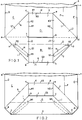
- Conventional paper sack-making machinery (not shown) is used to open-out and fold the paper tube A into the conventional, intermediate form shown in Fig. 1, with two mutually identical, trapezium-shaped flaps J and K.
- the trapezium-shaped flap J is formed (wholly out of a part of the face B) by a trapezium-shaped panel J1, the edges of which extend between points a-b-c-d-g-h-a, and two halves J2 and J3 (those extending between points a-b-h-a and between points d-c-g-d) of two respective triangular panels L1 and L2, defined by points a-b-h-f-a and by points d-c-g-e-d respectively.
- the trapezium-shaped flap K is formed (wholly out of a part of the reverse side C) by a trapezium-shaped panel K1, the edges of which extend between points a-f-e-d-g-h-a, and two halves K2 and K3 (those extending between points a-f-h-a and between points d-e-g-d) of the aforesaid two respective triangular panels L1 and L2.
- the bases a-h-g-d of the two trapezium-shaped flaps J, K are closely adjacent each other.
- panels L1 and L2 adjoin panel J1 along 45° folds i and j respectively and adjoin panel K1 along corresponding 45° folds k and I respectively.
- the top of the tube A is shown in Figs. 1 and 2 as torn off from point m on side edge fold D to point n on side edge fold E. In Figs. 3 and 4 somewhat more is shown torn off between corresponding points m' and n'.
- the two flaps J and K are mutually co-planar and could, unless inhibited, be pivoted about an axis a-h-g-d relative to the part of the tube A that extends up to points m and n from the aforesaid axis a-h-g-d.
- no such pivoting has any chance of occurring in the sack-making machinery as the sack tube proceeds through the successive folding steps described herein.
- edge portions G1-3, H1-3 border a rectangular area, defined by points b-c-g-e-f-h-b, which is actually an inside surface portion Bi of face B and an inside surface portion Ci of reverse side C and is in close contact with the flour when the sack is used; no adhesive must contact the flour, as mentioned earlier.
- the next step is to fold flap J upwardly on fold O, as shown in Fig. 2.
- This brings adhesive strips L and M into effective adhering contact with those parts of triangular panels L1 and L2 which are on the far side of fold O.
- Bottom edge portion G3 is thereby brought closer to bottom edge portion H3, an aperture P being defined by the rectangle defined by points b-c-e-f-b.
- next fold line Q is below bottom edge portion G3 but above points a and d as seen in Fig. 2. It will be observed that the inner ends M1, N1 of adhesive strips M and N project slightly across the fold line Q.
- Figs. 3 and 4 illustrate the sack preform, if it may be called that by this stage, after the flaps J and K have been folded downwardly on fold Q and after a rectangular, fully pasted (i.e. adhesive-coated) paper sheet, or "end label", R has been applied over flap K.
- the 45° folds i and k cross over at point q, whilst the 45° folds j and 1 cross over similarly at point r.
- points a, q, r and d are in alignment with each other.
- the label R is made to have a length q-r (that is, equal to the distance between points q and r) and a width equal to the distance between fold Q and edge portion H3, and is positioned accordingly to just touch points q and r and to be flush with fold Q and edge portion H3.
- the fold Q is in the opposite direction to the fold 0.
- Fig. 4 shows edge portions of flap K and label R projecting just below fold O.
- the only exposed adhesive is on side edge portions R1 and R2 of label R, projecting to the sides of flap K. There is no adhesive on flap K.
- the final step in forming the pasted bottom on the sack is to fold these projecting edge portions around fold O and stick down the side edge label portions R1 and R2.
- Fig. 4 shows the final positions thereof in chain-dot lines, immediately above fold O. Given that the only adhesive is on portions R1, R2, it will be appreciated that a gap exists, or can be easily opened up, along edge portion H3 between points e and f, as shown at S, where one can insert one's hand and pull the edge portions open again to the state shown in full lines in Figs. 3 and 4, allowing the flour to be poured out of outlet aperture P.
- the paper tube A from which the sack is made, is double-walled, so that the sack is also double-walled, the invention may be embodied in a single-walled paper sack or even a paper sack having three, or more, walls.
Abstract
A paper sack to be used for flour (or other granular or particulate material), having single - or multi-ply walls, has a pasted block bottom. The block bottom is designed so that it can be readily torn open to allow the sack contents to be poured out avoiding contamination by adhesive or torn paper fragments.
Two identical tapezium-shaped flaps (J,K) form the block bottom and onto these is pasted a rectangular label (R) leaving an un-pasted gap (S) where one can insert one's hand and pull open the pouring opening (P).
Two identical tapezium-shaped flaps (J,K) form the block bottom and onto these is pasted a rectangular label (R) leaving an un-pasted gap (S) where one can insert one's hand and pull open the pouring opening (P).
Description
- This invention relates to multi-wall paper sacks - a multi-wall paper sack being defined for the purposes of this specification as one having one or more walls.
- It is known for paper sacks to be used for flour (or other granular or particulate material, hereinafter comprised within the term "flour") intended to be used for human consumption. Such sacks commonly have so-called "pasted bottoms", by which is meant that the bottoms of the sacks are stuck down with paste or other adhesive. It is also known for such sacks to be designed so that the bottoms of the sacks can be readily torn open to pour out the flour. It is important for the flour not to be contaminated by the adhesive or by torn paper fragments and for the flour not to come into contact with any foreign thing or object or any part of a person, such as the hands, when the sack is opened..
- It is an object of the invention to provide a paper sack having a pasted bottom and suitable for sacking flour intended for human consumption.
- This is not to be interpreted as excluding other possible uses for the sack.
- According to the invention, there is provided a sack as claimed in claim 1, to which reference is directed.
- The invention will be described by way of example with reference to the drawings, wherein: -
- FIG. 1 illustrates a paper tube after a first, conventional, opening-out-and-folding step has been performed in the conversion of the tube into a sack embodying the invention, and showing where the next fold is to be made in accordance with the invention;
- FIG. 2 shows the tube after the next fold has been made and showing where the fold after that, the penultimate fold, is to be made;
- FIG. 3 shows the tube after the last-mentioned, penultimate, fold has been made and showing a pasted label applied; and
- FIG. 4 is a view corresponding to Fig. 3 from the other side of the sack and showing the position of the final fold.
- Referring to the drawings, the sack embodying the invention is a two-sided sack, made accordingly from a two-sided paper tube A, one side B of which (the "face", see Fig. 4) is joined directly to the other side C thereof (the "reverse side" or "seamed side", see Figs. 1 - 3) along two side edge folds D and E. Figs. 1 - 3 show the seam F of the reverse, or seamed, side C. The paper tube A is actually double walled, that is, formed by two separate paper tubes, one slightly smaller than, and inside, the other, but these two separate tubes are not shown as such. The drawings depict the double-walled tube A as if it were a single-walled tube. The bottom of the tube A is cut straight across with a "flush" cut, that is, with the bottom edges of the inner and outer tubes flush with each other and with the bottom edge G of the face B flush with the bottom edge H of the reverse side C.
- Conventional paper sack-making machinery (not shown) is used to open-out and fold the paper tube A into the conventional, intermediate form shown in Fig. 1, with two mutually identical, trapezium-shaped flaps J and K.
- The trapezium-shaped flap J is formed (wholly out of a part of the face B) by a trapezium-shaped panel J1, the edges of which extend between points a-b-c-d-g-h-a, and two halves J2 and J3 (those extending between points a-b-h-a and between points d-c-g-d) of two respective triangular panels L1 and L2, defined by points a-b-h-f-a and by points d-c-g-e-d respectively.
- The trapezium-shaped flap K is formed (wholly out of a part of the reverse side C) by a trapezium-shaped panel K1, the edges of which extend between points a-f-e-d-g-h-a, and two halves K2 and K3 (those extending between points a-f-h-a and between points d-e-g-d) of the aforesaid two respective triangular panels L1 and L2.
- The bases a-h-g-d of the two trapezium-shaped flaps J, K are closely adjacent each other.
- It will be understood that panels L1 and L2 adjoin panel J1 along 45° folds i and j respectively and adjoin panel K1 along corresponding 45° folds k and I respectively.
- The top of the tube A is shown in Figs. 1 and 2 as torn off from point m on side edge fold D to point n on side edge fold E. In Figs. 3 and 4 somewhat more is shown torn off between corresponding points m' and n'. As is well known in sack-making, the two flaps J and K are mutually co-planar and could, unless inhibited, be pivoted about an axis a-h-g-d relative to the part of the tube A that extends up to points m and n from the aforesaid axis a-h-g-d. However, no such pivoting has any chance of occurring in the sack-making machinery as the sack tube proceeds through the successive folding steps described herein.
- Other points to be mentioned with reference to Fig. 1, before proceeding with the description of subsequent folding with reference to Figs. 2 - 4, are: -
the bottom edges G and H of face B and reverse side C respectively are folded as shown in Fig. 1, where the 45° folds i, j, k and I respectively meet the edges G and H, leaving intermediate portions G3, H3 of the bottom edges G, H parallel to the bases a-h-g-d of the two trapezium-shaped flaps J, K but leaving side portions G1, G2, H1 and H2 perpendicular thereto. These edge portions G1-3, H1-3 border a rectangular area, defined by points b-c-g-e-f-h-b, which is actually an inside surface portion Bi of face B and an inside surface portion Ci of reverse side C and is in close contact with the flour when the sack is used; no adhesive must contact the flour, as mentioned earlier. - Two strips of adhesive paste M and N, each shaped as an elongate trapezium, are put onto the two half-panels J2 and J3 respectively as shown in Fig. 1. Inner ends Ml, Nl of these adhesive strips terminate just short of bottom edge portions G1, G2, to avoid contact with the flour. Outer ends M2, N2 terminate just short of a fold line O, shown by a broken line in Fig. 1, which is the location of the next fold to be made, as will now be described with reference to Fig. 2. Fold line O intercepts fold i (a-b) at point o and fold I (d-e) at point p.
- The next step is to fold flap J upwardly on fold O, as shown in Fig. 2. This brings adhesive strips L and M into effective adhering contact with those parts of triangular panels L1 and L2 which are on the far side of fold O. Bottom edge portion G3 is thereby brought closer to bottom edge portion H3, an aperture P being defined by the rectangle defined by points b-c-e-f-b. Eventually when the flour-filled sack is torn open to empty the flour, the flour will flow out of the sack through the aperture P, which is thus an outlet aperture.
- The next fold line Q is below bottom edge portion G3 but above points a and d as seen in Fig. 2. It will be observed that the inner ends M1, N1 of adhesive strips M and N project slightly across the fold line Q.
- Figs. 3 and 4 illustrate the sack preform, if it may be called that by this stage, after the flaps J and K have been folded downwardly on fold Q and after a rectangular, fully pasted (i.e. adhesive-coated) paper sheet, or "end label", R has been applied over flap K. The 45° folds i and k cross over at point q, whilst the 45° folds j and 1 cross over similarly at point r. Preferably points a, q, r and d are in alignment with each other. The label R is made to have a length q-r (that is, equal to the distance between points q and r) and a width equal to the distance between fold Q and edge portion H3, and is positioned accordingly to just touch points q and r and to be flush with fold Q and edge portion H3.
- The fold Q is in the opposite direction to the
fold 0. - Fig. 4 shows edge portions of flap K and label R projecting just below fold O. The only exposed adhesive is on side edge portions R1 and R2 of label R, projecting to the sides of flap K. There is no adhesive on flap K. The final step in forming the pasted bottom on the sack is to fold these projecting edge portions around fold O and stick down the side edge label portions R1 and R2. Fig. 4 shows the final positions thereof in chain-dot lines, immediately above fold O. Given that the only adhesive is on portions R1, R2, it will be appreciated that a gap exists, or can be easily opened up, along edge portion H3 between points e and f, as shown at S, where one can insert one's hand and pull the edge portions open again to the state shown in full lines in Figs. 3 and 4, allowing the flour to be poured out of outlet aperture P.
- Although the paper tube A, from which the sack is made, is double-walled, so that the sack is also double-walled, the invention may be embodied in a single-walled paper sack or even a paper sack having three, or more, walls.
Claims (4)
- A paper sack having a first side (B) joined directly to a second side (C) along two side edge folds (D, E) and having a pasted bottom formed from first and second trapezium-shaped flaps (J, K) formed by an opening-out and folding step;
the two said flaps (J, K) comprising two respective trapezium-shaped panels (J1, K1) formed, the first one from part of said first side (B) and the second one from part of said second side (C);
each said flap (J, K) also comprising two respective halves (J2, J3; K2, K3) of two triangular panels (L1, L2;) which adjoin said trapezium-shaped panels (J1, K1) along four 45° folds (i, j, k, l);
the bases (a-h-g-d) of the two trapezium-shaped flaps being closely adjacent each other;
a bottom edge (G, H) of each side (B, C) having an intermediate portion (G3, H3) parallel to the bases (a-h-g-d) of the two said flaps (J, K) and two side portions (G1, G2, H1, H2) perpendicular thereto;
the first flap (J) being folded on a first one (O) of three further folds (O, Q, O) to bring the intermediate bottom edge portion (G3) of said first side (B) closer to the intermediate bottom edge portion (H3) of said second side (C);
adhesive (M, N) causing to be adhered together facing portions of said two triangular panels (L1, L2) between said first one (O) and a second one (Q) of said three further folds;
an outlet aperture (P) being defined by a rectangle (b-c-e-f-b) formed by the two intermediate bottom edge portions (G3, H3) and by parts of the two side portions (H1, H2) of the bottom edge (H) of said second side (C);
there being no adhesive in the immediate vicinity of said outlet aperture (P);
the two said flaps then being folded in an opposite direction about the second one (Q) of said three further folds, said second one (O) of said three further folds being between the intermediate bottom edge portion (G3) of said first side (B) and the bases (a-h-g-d) of the two trapezium-shaped flaps (J, K), to bring an edge portion of the second trapezium-shaped flap (K), but no portion of the first trapezium-shaped flap (J), across the first one (O) of said three further folds (O, Q, O);
an adhesive-coated sheet (R) being applied over said second trapezium-shaped flap (K);
and edge portions of said second trapezium-shaped flap (K) and said sheet (R) being folded in the third one (O) of said three further folds about said first one (O) of said folds, in the same direction as the second one (Q) of said folds, stuck down adhesively by side edge portions of said sheet (R). - A paper sack as claimed in claim 1, wherein said first side (B) is a face of the sack and the second side (C) is a seamed side or reverse side of the sack.
- A paper sack as claimed in claim 1 or 2, wherein a small amount of adhesive (M1, N1) is provided on the far side of said second fold (Q) from said first fold (O).
- A paper sack as claimed in any preceding claim, wherein the sack has two or more walls, with flush-cut ends.
Applications Claiming Priority (2)
| Application Number | Priority Date | Filing Date | Title |
|---|---|---|---|
| GB9305556 | 1993-03-18 | ||
| GB9305556A GB2276141B (en) | 1993-03-18 | 1993-03-18 | Paper sacks |
Publications (1)
| Publication Number | Publication Date |
|---|---|
| EP0618145A1 true EP0618145A1 (en) | 1994-10-05 |
Family
ID=10732265
Family Applications (1)
| Application Number | Title | Priority Date | Filing Date |
|---|---|---|---|
| EP94301924A Withdrawn EP0618145A1 (en) | 1993-03-18 | 1994-03-17 | Paper sacks |
Country Status (2)
| Country | Link |
|---|---|
| EP (1) | EP0618145A1 (en) |
| GB (1) | GB2276141B (en) |
Citations (2)
| Publication number | Priority date | Publication date | Assignee | Title |
|---|---|---|---|---|
| GB880250A (en) * | 1959-08-17 | 1961-10-18 | Paper Sacks Ltd | Improvements in and relating to multi-ply paper bags or sacks |
| FR2228680A1 (en) * | 1973-05-10 | 1974-12-06 | Windmoeller & Hoelscher |
-
1993
- 1993-03-18 GB GB9305556A patent/GB2276141B/en not_active Expired - Fee Related
-
1994
- 1994-03-17 EP EP94301924A patent/EP0618145A1/en not_active Withdrawn
Patent Citations (2)
| Publication number | Priority date | Publication date | Assignee | Title |
|---|---|---|---|---|
| GB880250A (en) * | 1959-08-17 | 1961-10-18 | Paper Sacks Ltd | Improvements in and relating to multi-ply paper bags or sacks |
| FR2228680A1 (en) * | 1973-05-10 | 1974-12-06 | Windmoeller & Hoelscher |
Also Published As
| Publication number | Publication date |
|---|---|
| GB2276141B (en) | 1996-07-31 |
| GB2276141A (en) | 1994-09-21 |
| GB9305556D0 (en) | 1993-05-05 |
Similar Documents
| Publication | Publication Date | Title |
|---|---|---|
| US5392589A (en) | Method of constructing a container with unitary spout pull tab | |
| US4953708A (en) | Flexible package with pour spout and handle | |
| US4480752A (en) | Pinch closure bags with opening feature and method of manufacturing them | |
| US4196030A (en) | Method of making extruded construction for bags | |
| JP3068851B2 (en) | Reclosable paperboard box for granules | |
| US3819093A (en) | Slide top dispensing carton | |
| US4691858A (en) | Milk carton blank and milk carton with pour spout | |
| US5918799A (en) | Carton, carton blank and method for forming the carton | |
| US5505374A (en) | Flip-top reclosable carton and method of making the same | |
| US5551938A (en) | Recloseable container with press-bonded collar | |
| US20060034551A1 (en) | Reclosable containers | |
| US20100142858A1 (en) | Plastic bag with pour spout and slide closure | |
| US2903175A (en) | Folding box | |
| CA2522517A1 (en) | Package having reclosable pour spout and method of forming same | |
| MX2010011301A (en) | Bag structures and methods of assembling the same. | |
| US3561669A (en) | Composite leakproof carton | |
| EP0822145A1 (en) | Paperboard carton having a pour spout and blank for forming the same | |
| US3826421A (en) | Severable carton with sterile edge | |
| US3478868A (en) | Sterilizable containers | |
| US4989735A (en) | Dispensing carton | |
| AU2002360132A1 (en) | Resealable flexible package | |
| US5029751A (en) | Pack made from a single-piece board blank | |
| US5680986A (en) | Carton with pour spout formed by liner | |
| CA1171823A (en) | Easy open carton | |
| US5325989A (en) | Box and blank for packaging powdered soap or the like |
Legal Events
| Date | Code | Title | Description |
|---|---|---|---|
| PUAI | Public reference made under article 153(3) epc to a published international application that has entered the european phase |
Free format text: ORIGINAL CODE: 0009012 |
|
| AK | Designated contracting states |
Kind code of ref document: A1 Designated state(s): DE FR GB IT SE |
|
| STAA | Information on the status of an ep patent application or granted ep patent |
Free format text: STATUS: THE APPLICATION IS DEEMED TO BE WITHDRAWN |
|
| 18D | Application deemed to be withdrawn |
Effective date: 19950406 |