EP0618101B1 - Sealing arrangement for a preferably frameless window pane of a motor vehicle - Google Patents
Sealing arrangement for a preferably frameless window pane of a motor vehicle Download PDFInfo
- Publication number
- EP0618101B1 EP0618101B1 EP94102047A EP94102047A EP0618101B1 EP 0618101 B1 EP0618101 B1 EP 0618101B1 EP 94102047 A EP94102047 A EP 94102047A EP 94102047 A EP94102047 A EP 94102047A EP 0618101 B1 EP0618101 B1 EP 0618101B1
- Authority
- EP
- European Patent Office
- Prior art keywords
- sealing device
- roof frame
- window pane
- sealing
- arm
- Prior art date
- Legal status (The legal status is an assumption and is not a legal conclusion. Google has not performed a legal analysis and makes no representation as to the accuracy of the status listed.)
- Expired - Lifetime
Links
Images

Classifications
-
- B—PERFORMING OPERATIONS; TRANSPORTING
- B60—VEHICLES IN GENERAL
- B60J—WINDOWS, WINDSCREENS, NON-FIXED ROOFS, DOORS, OR SIMILAR DEVICES FOR VEHICLES; REMOVABLE EXTERNAL PROTECTIVE COVERINGS SPECIALLY ADAPTED FOR VEHICLES
- B60J10/00—Sealing arrangements
- B60J10/20—Sealing arrangements characterised by the shape
- B60J10/24—Sealing arrangements characterised by the shape having tubular parts
-
- B—PERFORMING OPERATIONS; TRANSPORTING
- B60—VEHICLES IN GENERAL
- B60J—WINDOWS, WINDSCREENS, NON-FIXED ROOFS, DOORS, OR SIMILAR DEVICES FOR VEHICLES; REMOVABLE EXTERNAL PROTECTIVE COVERINGS SPECIALLY ADAPTED FOR VEHICLES
- B60J10/00—Sealing arrangements
- B60J10/30—Sealing arrangements characterised by the fastening means
-
- B—PERFORMING OPERATIONS; TRANSPORTING
- B60—VEHICLES IN GENERAL
- B60J—WINDOWS, WINDSCREENS, NON-FIXED ROOFS, DOORS, OR SIMILAR DEVICES FOR VEHICLES; REMOVABLE EXTERNAL PROTECTIVE COVERINGS SPECIALLY ADAPTED FOR VEHICLES
- B60J10/00—Sealing arrangements
- B60J10/70—Sealing arrangements specially adapted for windows or windscreens
- B60J10/74—Sealing arrangements specially adapted for windows or windscreens for sliding window panes, e.g. sash guides
Definitions
- the invention relates to a sealing device for a preferably frameless window of a motor vehicle according to the preamble of patent claim 1.
- a holding element provided with an undercut receptacle is first attached to the roof frame above by means of screws. Then the sealing body is inserted into the receptacle of the holding element. If you now determine during assembly that the sealing body is not seated correctly in relation to the viewing window, the sealing body must be removed from the holding element again and only then can the position of the holding element be readjusted.
- This arrangement has the disadvantage that the sealing device consists of two separate parts and that the assembly and adjustment of the sealing device is laborious and time-consuming.
- the object of the invention is to develop a sealing device held in position on a roof frame in such a way that it can be fastened to the roof frame quickly and in an assembly-friendly manner with a simple structure.
- the one-piece design of the sealing body on the roof frame enables a simple, inexpensive construction and a substantially improved assembly and adjustment of the sealing body on the roof frame.
- the direct attachment to the roof frame is possible because of a Profile section of the sealing body can be connected to the sealing body via a releasable snap connection. To insert and screw in the screw, the profile section is pivoted into a release position that ensures access to the screw.
- a reinforcing insert connected to the holding section or embedded in it is profiled approximately in a U-shape, a first outer leg serving for the viewing pane to move outward only by a defined amount at relatively high driving speeds and the negative pressure that then arises on the longitudinal sides of the vehicle can.
- the first leg effectively causes the disk to claw with the sealing body.
- the releasable snap connection is provided in the area of the second leg of the reinforcement insert, which ensures simple detachment or connection of the two parts of the sealing body.
- the snap connection is provided between the profile section and the holding section, whereas in a second embodiment the snap connection is formed between the profile section and the reinforcing insert of the sealing body.
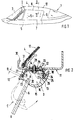
- the motor vehicle 1 formed by a passenger car comprises a frame 2 held in the area shown Windshield 3, a roof 4 and side doors 5 (Fig.1).
- Each door 5 has a height-adjustable viewing window 6, which is displaceably mounted within the door body in guide rails (not shown).
- the lens 6 is frameless above a belt line 7 at least along its approximately horizontal upper edge 8 and a rear vertical boundary 8.
- the roof frame 11 forms the lateral boundary of a folding roof 12.
- the roof frame 11 is part of a removable roof or of a roof that is firmly connected to the body.
- the sealing device 10 comprises a sealing body 13, which is composed essentially of a holding section 14 running adjacent to the roof frame 11 and a profile section 15 which interacts with the lens 6.
- the holding section 14 and the profile section 15 connected to it define at least one internal, closed cavity 16.
- the tubular sealing body 13 is screwed directly onto the roof frame 11 without the interposition of an additional holding element.
- the screw 17 is arranged in a central region of the transverse extent of the sealing body 13. This is made possible by the fact that the profile section 15 cooperating with the lens 6 is detachably connected to the holding section 14 via a snap connection 18.
- the profile section 15 When the sealing device 10 is installed, the profile section 15 is in a release position C shown in dash-dotted lines, in accordance with the delivery state of the sealing body 13, in which the screw 17 is easily accessible. After the screw 17 has been inserted and screwed in, the profile section 15 is folded up and connected in a simple manner to the holding section 14 via the snap connection 18 (end position D).
- the holding section 14 of the sealing body 13 is provided with a reinforcing insert 19 made of metal or plastic, this reinforcing insert 19 according to FIG. 2 being completely embedded in the material of the holding section 14 with the exception of a support area 20 for a washer 21.
- the reinforcing insert 19 is profiled approximately U-shaped.
- a first, outer leg 22 of the reinforcing insert 19 runs approximately parallel to the plane A-A of the viewing window 6, the leg 22 or its casing 23 projecting downward beyond the viewing window 6 by a dimension B.
- the leg 22 can also run at an angle to the viewing plane A-A.
- the second leg 24 of the reinforcing insert 19 is oriented approximately at right angles to the roof frame 11.
- the releasable snap connection 18 is provided in the region of the free end of the leg 24 which is also directed downward.
- the snap connection 18 comprises a barb-shaped element 25 which interacts with a corresponding undercut receptacle 26.
- the snap connection 18 is provided on the leg 24 of the reinforcing insert 19 facing the interior.
- the barb-shaped element 25 is assigned to the holding section 14, whereas the undercut receptacle 26 is formed on the profile section 15. In the area of the receptacle 26, the profile section 15 is divided into two lip sections.
- the two elements of the snap connection 18 can also be designed the other way round.
- the barb-shaped element 25 extends on both sides of the downwardly directed leg 24 and surrounds it on all sides.
- a strip 31 forming a rain gutter 30 is inserted between an external section 29 of the roof frame 11 and the holding section 14 of the sealing body 13, which is held in position with the screw 17 together with the sealing body 13 on the roof frame 11 is.
- the holding section 14 has a plurality of protruding longitudinal grooves 32 on the side facing the bar.
- the bar 31 is additionally fastened to the underside of the section 29 of the roof frame 11 by means of double-sided adhesive tape 33.
- Fig. 3 shows a second embodiment of a sealing device 10, wherein the sealing body 13 'assumes an end position D.
- the sealing body 13 ' is composed of a holding section 14' running adjacent to the roof frame 11 and a profile section 15 'which interacts with the lens 6.
- the reinforcing insert 19 ' is formed by an extruded profile made of metal (aluminum) or plastic, which is firmly connected to the holding section 14' by gluing or vulcanization. The reinforcing insert 19 'lies against the side of the holding section 14' facing away from the roof frame 11 and is fastened thereon.
- the releasable snap connection 18 ' is provided between the profile section 15' and the reinforcing insert 19 'of the sealing body 13'.
- the snap connection 18 ' comprises a barb-shaped element 25' which interacts with a corresponding undercut receptacle 26 '.
- the receptacle 26 ' is formed on the profile section 15, whereas the barb-shaped element 25' is provided on the leg 24 'of the reinforcing insert 19'.
- the barb-shaped element 25 ' is formed by a cross-sectional widening 34 in the region of the free end of the leg 24', the shape of the cross-sectional widening 34 being adapted to the receptacle 26 '.
Description
Die Erfindung betrifft eine Dichtungseinrichtung für eine vorzugsweise rahmenlose Sichtscheibe eines Kraftfahrzeuges gemäß dem Oberbegriff des Patentanspruchs 1.The invention relates to a sealing device for a preferably frameless window of a motor vehicle according to the preamble of patent claim 1.
Bei einer bekannten Dichtungseinrichtung (US-A-40 60 272) wird zuerst ein mit einer hinterschnittenen Aufnahme versehenes Halteelement mittels Schrauben am darüberliegenden Dachrahmen befestigt. Danach wird der Dichtkörper in die Aufnahme des Haltelelemtes eingesetzt. Stellt man nun bei der Montage fest, daß der Dichtkörper nicht lagerichtig zur Sichtscheibe sitzt, so muß der Dichtkörper wieder aus dem Halteelement herausgenommen werden und erst danach kann die Lage des Halteelementes neu eingestellt werden. Dieser Anordnung haftet der Nachteil an, daß die Dichtungseinrichtung aus zwei separaten Teilen besteht und daß die Montage und Einstellung der Dichtungseinrichtung umständlich und zeitaufwendig ist.In a known sealing device (US-A-40 60 272), a holding element provided with an undercut receptacle is first attached to the roof frame above by means of screws. Then the sealing body is inserted into the receptacle of the holding element. If you now determine during assembly that the sealing body is not seated correctly in relation to the viewing window, the sealing body must be removed from the holding element again and only then can the position of the holding element be readjusted. This arrangement has the disadvantage that the sealing device consists of two separate parts and that the assembly and adjustment of the sealing device is laborious and time-consuming.
Aufgabe der Erfindung ist es, eine an einem Dachrahmen in Lage gehaltene Dichtungseinrichtung so weiterzubilden, daß sie bei einfachem Aufbau schnell und montagefreundlich am Dachrahmen befestigbar ist.The object of the invention is to develop a sealing device held in position on a roof frame in such a way that it can be fastened to the roof frame quickly and in an assembly-friendly manner with a simple structure.
Erfindungsgemäß wird dies durch die kennzeichnenden Merkmale des Anspruchs 1 gelöst. Weitere, die Erfindung in vorteilhafter Weise ausgestaltende Merkmale enthalten die Unteransprüche.According to the invention, this is solved by the characterizing features of claim 1. Further features which advantageously design the invention contain the subclaims.
Die mit der Erfindung hauptsächlich erzielten Vorteile sind darin zu sehen, daß durch die einteilige Ausbildung des Dichtkörpers am Dachrahmen ein einfacher kostengünstiger Aufbau und eine wesentlich verbesserte Montage und Einstellung des Dichtkörpers am Dachrahmen ermöglicht wird. Die unmittelbare Befestigung am Dachrahmen ist möglich, da ein Profilabschnitt des Dichtkörpers über eine lösbare Schnappverbindung mit dem Dichtkörper verbindbar ist. Zum Einsetzen und Eindrehen der Schraube wird der Profilabschnitt in eine die Zugänglichkeit zur Schraube gewährende Freigabestellung verschwenkt.The main advantages achieved with the invention can be seen in the fact that the one-piece design of the sealing body on the roof frame enables a simple, inexpensive construction and a substantially improved assembly and adjustment of the sealing body on the roof frame. The direct attachment to the roof frame is possible because of a Profile section of the sealing body can be connected to the sealing body via a releasable snap connection. To insert and screw in the screw, the profile section is pivoted into a release position that ensures access to the screw.
Eine mit dem Halteabschnitt verbundene bzw. in diesen eingebettete Verstärkungseinlage ist etwa U-förmig profiliert, wobei ein erster außenliegender Schenkel dazu dient, daß sich die Sichtscheibe bei relativ hohen Fahrgeschwindigkeiten und dem dann entstehenden Unterdruck an den Fahrzeuglängsseiten nur um einen definierten Betrag nach außen bewegen kann. Der erste Schenkel bewirkt quasi ein Verkrallen der Scheibe mit dem Dichtkörper.A reinforcing insert connected to the holding section or embedded in it is profiled approximately in a U-shape, a first outer leg serving for the viewing pane to move outward only by a defined amount at relatively high driving speeds and the negative pressure that then arises on the longitudinal sides of the vehicle can. The first leg effectively causes the disk to claw with the sealing body.
Im Bereich des zweiten Schenkels der Verstärkungseinlage ist die lösbare Schnappverbindung vorgesehen, die ein einfaches Lösen bzw. Verbinden der beiden Teile des Dichtkörpers gewährleistet. Bei einer ersten Ausführungsform ist die Schnappverbindung zwischen dem Profilabschnitt und dem Halteabschnitt vorgesehen, wogegen bei einer zweiten Ausführungsform die Schnappverbindung zwischen dem Profilabschnitt und der Verstärkungseinlage des Dichtkörpers ausgebildet ist.In the area of the second leg of the reinforcement insert, the releasable snap connection is provided, which ensures simple detachment or connection of the two parts of the sealing body. In a first embodiment, the snap connection is provided between the profile section and the holding section, whereas in a second embodiment the snap connection is formed between the profile section and the reinforcing insert of the sealing body.
Ein Ausführungsbeispiel der Erfindung ist in der Zeichnung dargestellt und wird im folgenden näher erläutert:An embodiment of the invention is shown in the drawing and is explained in more detail below:
Es zeigt
- Fig. 1
- eine Seitenansicht eines Personenwagens
- Fig. 2
- einen Schnitt nach der Linie II-II der Fig. 1 in größerem Maßstab einer ersten Ausführungsform einer Dichtungseinrichtung
- Fig. 3
- einen Schnitt ähnlich Fig. 2 einer zweiten Ausführungsform der Dichtungseinrichtung
- Fig. 1
- a side view of a passenger car
- Fig. 2
- a section along the line II-II of Fig. 1 on a larger scale a first embodiment of a sealing device
- Fig. 3
- a section similar to FIG. 2 of a second embodiment of the sealing device
Das durch einen Personenwagen gebildete Kraftfahrzeug 1 umfaßt im dargestellten Bereich eine von einem Rahmen 2 gehaltene Windschutzscheibe 3, ein Dach 4 sowie seitliche Türen 5 (Fig.1).The motor vehicle 1 formed by a passenger car comprises a
Jede Tür 5 weist eine höhenverstellbare Sichtscheibe 6 auf, die in nicht näher dargestellten Führungsschienen innerhalb des Türkörpers verschiebbar gelagert ist. Die Sichtscheibe 6 ist oberhalb einer Gürtellinie 7 zumindest entlang ihres etwa horizontal verlaufenden oberen Randes 8 und einer hinteren vertikalen Begrenzung 8 rahmenlos ausgebildet.Each
Der obere Rand 8 der Sichtscheibe 6, die durch eine Türfensterscheibe dargestellt ist, wirkt gemäß Fig. 2 mit einer Dichtungseinrichtung 10 zusammen, die an einem seitlichen Dachrahmen 11 des Daches 4 befestigt ist.The
Der Dachrahmen 11 bildet im Ausführungsbeispiel die seitliche Begrenzung eines Faltverdeckes 12. Es besteht aber auch die Möglichkeit, daß der Dachrahmen 11 Teil eines herausnehmbaren Daches oder eines fest mit der Karosserie verbundenen Daches ist.In the exemplary embodiment, the
Die Dichtungseinrichtung 10 umfaßt gemäß einer ersten Ausführungsform (Fig. 2) einen Dichtkörper 13, der sich im wesentlichen aus einem benachbart dem Dachrahmen 11 verlaufenden Halteabschnitt 14 und einem mit der Sichtscheibe 6 zusammenwirkenden Profilabschnitt 15 zusammensetzt. Der Halteabschnitt 14 und der an diesen angeschlossene Profilabschnitt 15 definieren zumindest einen innenliegenden, geschlossenen Hohlraum 16.According to a first embodiment (FIG. 2), the
Erfindungsgemäß ist vorgesehen, daß der schlauchförmige Dichtkörper 13 ohne Zwischenschaltung eines zusätzlichen Halteelementes unmittelbar am Dachrahmen 11 angeschraubt ist. Die Schraube 17 ist in einem mittleren Bereich der Quererstreckung des Dichtkörpers 13 angeordnet. Dies wird dadurch ermöglicht, daß der mit der Sichtscheibe 6 zusammenwirkende Profilabschnitt 15 über eine Schnappverbindung 18 mit dem Halteabschnitt 14 lösbar verbunden ist.According to the invention it is provided that the
Bei der Montage der Dichtungseinrichtung 10 befindet sich der Profilabschnitt 15 entsprechend dem Anlieferungszustand des Dichtkörpers 13 in einer strichpunktiert dargestellten Freigabestellung C, in der eine gute Zugänglichkeit zur Schraube 17 gegeben ist. Nach dem Einsetzen und Eindrehen der Schraube 17 wird der Profilabschnitt 15 nach oben geklappt und über die Schnappverbindung 18 mit dem Halteabschnitt 14 in einfacher Weise verbunden (Endstellung D).When the
Der Halteabschnitt 14 des Dichtkörper 13 ist mit einer Verstärkungseinlage 19 aus Metall oder Kunststoff versehen, wobei diese Verstärkungseinlage 19 gemäß Fig. 2 mit Ausnahme eines Auflagebereiches 20 für eine Unterlegscheibe 21 vollständig in das Material des Halteabschnitts 14 eingebettet ist.The holding section 14 of the sealing
Die Verstärkungseinlage 19 ist etwa U-förmig profiliert. Ein erster, außenliegender Schenkel 22 der Verstärkungseinlage 19 verläuft annähernd parallel zur Ebene A-A der Sichtscheibe 6, wobei der Schenkel 22 bzw. dessen Ummantelung 23 die Sichtscheibe 6 um ein Maß B nach unten hin überragen.The reinforcing
Der Schenkel 22 kann auch unter einem Winkel zur Sichtscheibenebene A-A verlaufen.The
Bei relativ hohen Fahrgeschwindigkeiten tritt an den Fahrzeuglängsseiten ein Unterdruck auf, der insbesondere bei Cabriolets die rahmenlosen Sichtscheiben 6 nach außen bewegt. Dies wird bei der erfindunsgemäßen Ausführung durch den Schenkel 22 und den Profilabschnitt 15, der sich um das freie Ende des Schenkels 22 legt, vermieden.At relatively high driving speeds, a negative pressure occurs on the longitudinal sides of the vehicle, which in particular in the case of convertibles, moves the
Der zweite Schenkel 24 der Verstärkungseinlage 19 ist etwa rechtwinkelig zum Dachrahmen 11 ausgerichtet. Im Bereich des freien Endes des ebenfalls nach unten hin gerichteten Schenkels 24 ist die lösbare Schnappverbindung 18 vorgesehen.The
Die Schnappverbindung 18 umfaßt ein widerhakenförmig ausgebildetes Element 25, das mit einer korrespondierenden hinterschnittenen Aufnahme 26 zusammenwirkt.The
Gemäß Fig. 2 ist die Schnappverbindung 18 an dem dem Innenraum zugekehrten Schenkel 24 der Verstärkungseinlage 19 vorgesehen.2, the
Das widerhakenförmige Element 25 ist dem Halteabschnitt 14 zugeordnet, wogegen die hinterschnittene Aufnahme 26 am Profilabschnitt 15 ausgebildet ist. Im Bereich der Aufnahme 26 teilt sich der Profilabschnitt 15 in zwei Lippenabschnitte auf. Die beiden Elemente der Schnappverbindung 18 können auch umgekehrt ausgebildet sein. Das widerhakenförmige Element 25 erstreckt sich beiderseits des nach unten gerichteten Schenkels 24 und umgibt diesen allseitig.The barb-
Ein etwa parallel zur Unterseite des Dachrahmens 11 verlaufender Verbindungssteg 27 zwischen den beiden Schenkeln 22,24 sowie der Halteabschnitt 14 weisen im Bereich der Schraube 17 eine Durchgangsbohrung 28 auf, die einen wesentlich größeren Durchmesser besitzt als der Durchmesser der Schraube 17. Hierdurch ist eine Einstellmöglichkeit, insbesondere in Fahrzeugquerrichtung, gegeben.An approximately parallel to the underside of the
Gemäß Fig.2 ist zwischen einem außenliegenden, nach oben hin abgesetzten Abschnitt 29 des Dachrahmens 11 und dem Halteabschnitt 14 des Dichtkörpers 13 eine eine Regenrinne 30 bildende Leiste 31 eingeschoben, die mit der Schraube 17 zusammen mit dem Dichtkörper 13 am Dachrahmen 11 in Lage gehalten ist. Der Halteabschnitt 14 weist auf der der Leiste zugekehrten Seite mehrere vorstehende Längsrillen 32 auf.Die Leiste 31 ist zusätzlich über ein doppelseitiges Klebeband 33 an der Unterseite des Abschnitts 29 des Dachrahmens 11 befestigt.According to FIG. 2, a strip 31 forming a
Fig. 3 zeigt eine zweite Ausführungsform einer Dichtungseinrichtung 10, wobei der Dichtkörper 13' eine Endstellung D einnimmt.Fig. 3 shows a second embodiment of a
Der Dichtkörper 13' setzt sich aus einem benachbart dem Dachrahmen 11 verlaufenden Halteabschnitt 14' und einem mit der Sichtscheibe 6 zusammenwirkenden Profilabschnitt 15' zusammen. Bei der zweiten Ausführungsform wird die Verstärkungseinlage 19' durch ein Strangpreßprofil aus Metall (Alu) oder Kunststoff gebildet, das mit dem Halteabschnitt 14' durch Kleben oder Vulkanisieren fest verbunden ist. Die Verstärkungseinlage 19' liegt an der dem Dachrahmen 11 abgekehrten Seite des Halteabschnittes 14' an und ist an diesem befestigt.The sealing body 13 'is composed of a holding section 14' running adjacent to the
Es besteht jedoch auch die Möglichkeit, daß die Verstärkungseinlage 19' zumindest abschnittsweise in den Halteabschnitt 14' eingebettet ist.
Gemäß Fig. 3 ist die lösbare Schnappverbindung 18' zwischen dem Profilabschnitt 15' und der Verstärkungseinlage 19' des Dichtkörpers 13' vorgesehen.
Die Schnappverbindung 18' umfaßt ebenso wie bei der ersten Ausführungsform ein widerhakenförmig ausgebildetes Element 25', das mit einer korrespondierenden hinterschnittenen Aufnahme 26' zusammenwirkt.
Die Aufnahme 26' ist am Profilabschnitt 15 ausgebildet, wogegen das widerhakenförmige Element 25' am Schenkel 24' der Verstärkungseinlage 19' vorgesehen ist. Das widerhakenförmige Element 25' wird durch eine Querschnittserweiterung 34 im Bereich des freien Endes des Schenkels 24' gebildet, wobei die Form der Querschnittserweiterung 34 der Aufnahme 26' angepaßt ist.However, there is also the possibility that the reinforcing insert 19 'is embedded at least in sections in the holding section 14'.
According to FIG. 3, the releasable snap connection 18 'is provided between the profile section 15' and the reinforcing insert 19 'of the sealing body 13'.
As in the first embodiment, the snap connection 18 'comprises a barb-shaped element 25' which interacts with a corresponding undercut receptacle 26 '.
The receptacle 26 'is formed on the
Claims (11)
- A sealing device (10, 10') for a preferably frameless window pane of a motor vehicle, held in position on a lateral roof frame (11) opposite thereto by means of screws (17) and provided with a sealing member (13, 13') which comprises a retaining portion (14, 14') extending adjacent to the roof frame (11) and a sectioned portion (15, 15') bounding at least one cavity (16, 16') and cooperating with the window pane (6), characterized in that the sealing member (13, 13') is secured directly to the roof frame (11) by means of screws (17) without the interposition of an additional retaining member, wherein the sectioned portion (15, 15') cooperating with the window pane (6) occupies a release position C directed downwards for the insertion and tightening of the screw (17), and the sectioned portion (15, 15') can be releasably connected to the sealing member (13, 13') by way of a snap fastening (18, 18').
- A sealing device according to Claim 1, characterized in that a reinforcement inlay (19, 19') is provided in the retaining portion (14, 14') facing the roof frame (11).
- A sealing device according to Claims 1 and 2, characterized in that the reinforcement inlay (19, 19') connected to the retaining portion (14, 14') or embedded therein has a substantially U-shaped section.
- A sealing device according to Claim 3, characterized in that a first external arm (22, 22') of the reinforcement inlay (19, 19') is orientated substantially parallel to the plane A-A of the window pane (6), wherein the said arm (22, 22') or the covering (23) thereof projects downwards by an amount B beyond the window pane (6).
- A sealing device according to one of Claims 1 to 3, characterized in that the second arm (24, 24') of the reinforcement inlay (19, 19') is orientated substantially at a right angle to the roof frame (11), and the releasable snap fastening (18, 18') is provided in the region of the second arm (24, 24').
- A sealing device according to Claims 1 to 5, characterized in that the sectioned portion (15) can be releasably connected to the retaining portion (14) of the sealing member (13) by way of the snap fastening (18).
- A sealing device according to Claims 1 and 6, characterized in that the snap fastening (18) comprises a barb-shaped member (25) which cooperates with a corresponding undercut receiving means (26).
- A sealing device according to Claim 7, characterized in that the barb-shaped member (25) is formed on the retaining portion (14) and the receiving means (26) is formed on the sectioned portion (15) of the sealing member (13).
- A sealing device according to one or more of the preceding Claims, characterized in that in the region of a washer (21) for the screw (17) the reinforcement inlay (19) has no covering locally, so that the washer (21) rests directly on the reinforcement inlay (19).
- A sealing device according to one or more of the preceding Claims, characterized in that the sectioned portion (15') can be releasably connected to the reinforcement inlay (19') of the sealing member (13') by way of the snap fastening (18').
- A sealing device according to Claim 10, characterized in that the snap fastening (18') is formed by an undercut receiving means (26') arranged on the sectioned portion (15') and by a barb-shaped member (25') provided on the reinforcement inlay (19'), wherein the member (25') is provided in the region of the free, downwardly directed end of the arm (24') and is formed by a cross-sectional widening (34) of the arm (24').
Applications Claiming Priority (4)
| Application Number | Priority Date | Filing Date | Title |
|---|---|---|---|
| DE4310880 | 1993-04-02 | ||
| DE4310880 | 1993-04-02 | ||
| DE4320330A DE4320330C2 (en) | 1993-04-02 | 1993-06-18 | Sealing device for a frameless window of a motor vehicle |
| DE4320330 | 1993-06-18 |
Publications (3)
| Publication Number | Publication Date |
|---|---|
| EP0618101A2 EP0618101A2 (en) | 1994-10-05 |
| EP0618101A3 EP0618101A3 (en) | 1995-03-15 |
| EP0618101B1 true EP0618101B1 (en) | 1997-04-16 |
Family
ID=25924613
Family Applications (1)
| Application Number | Title | Priority Date | Filing Date |
|---|---|---|---|
| EP94102047A Expired - Lifetime EP0618101B1 (en) | 1993-04-02 | 1994-02-10 | Sealing arrangement for a preferably frameless window pane of a motor vehicle |
Country Status (1)
| Country | Link |
|---|---|
| EP (1) | EP0618101B1 (en) |
Cited By (1)
| Publication number | Priority date | Publication date | Assignee | Title |
|---|---|---|---|---|
| US11485209B2 (en) | 2020-06-29 | 2022-11-01 | Ford Global Technologies, Llc | Adjustable glass track systems for vehicles with frameless doors |
Families Citing this family (10)
| Publication number | Priority date | Publication date | Assignee | Title |
|---|---|---|---|---|
| DE4442458C1 (en) * | 1994-11-29 | 1996-02-22 | Bayerische Motoren Werke Ag | Water run=off device for convertible or similar vehicle |
| DE19801870C2 (en) | 1998-01-20 | 2001-09-27 | Porsche Ag | Sealing device for at least one frameless window of a motor vehicle |
| US6205712B1 (en) | 1998-07-29 | 2001-03-27 | Decoma Exterior Trim Inc. | Decorative molding assembly for a vehicle door frame |
| DE19928724C2 (en) * | 1999-06-23 | 2002-08-14 | Daimler Chrysler Ag | Sealing device in an opening which can be closed by a displaceable part, in particular a frameless pane of a motor vehicle |
| DE29916383U1 (en) * | 1999-09-17 | 2000-10-26 | Baedje K H Meteor Gummiwerke | Window sealing profile for a convertible |
| DE60102465T2 (en) | 2000-04-27 | 2005-01-27 | Asahi Glass Co., Ltd. | Mounting structure for a window glass and removal method for a window glass |
| DE10024567A1 (en) * | 2000-05-19 | 2001-11-29 | Saar Gummiwerk Gmbh | Fastening system for strand-like elastic sealing elements |
| DE10131774C1 (en) * | 2001-07-03 | 2002-06-20 | Cts Fahrzeug Dachsysteme Gmbh | Sealing element for movable component of vehicle has carrier body divided into at least two sectors by integral hinge |
| DE20111998U1 (en) * | 2001-07-19 | 2002-08-29 | Baedje K H Meteor Gummiwerke | Window sealing profile for a convertible |
| DE102005043264A1 (en) | 2005-09-09 | 2007-03-15 | Wilhelm Karmann Gmbh | Cabriolet vehicle with a soft top |
Family Cites Families (2)
| Publication number | Priority date | Publication date | Assignee | Title |
|---|---|---|---|---|
| JPS5066323U (en) * | 1973-10-19 | 1975-06-14 | ||
| DE3836687C2 (en) * | 1988-10-28 | 1995-11-09 | Audi Ag | Roof molding for a motor vehicle |
-
1994
- 1994-02-10 EP EP94102047A patent/EP0618101B1/en not_active Expired - Lifetime
Cited By (1)
| Publication number | Priority date | Publication date | Assignee | Title |
|---|---|---|---|---|
| US11485209B2 (en) | 2020-06-29 | 2022-11-01 | Ford Global Technologies, Llc | Adjustable glass track systems for vehicles with frameless doors |
Also Published As
| Publication number | Publication date |
|---|---|
| EP0618101A3 (en) | 1995-03-15 |
| EP0618101A2 (en) | 1994-10-05 |
Similar Documents
| Publication | Publication Date | Title |
|---|---|---|
| DE69634309T2 (en) | Device for closing a vehicle opening, with sliding window | |
| DE69930208T2 (en) | Profilteilbefestigung for the load carrier of a motor vehicle | |
| DE69924734T2 (en) | SUNROOF DESIGN FOR VEHICLES, AND VEHICLES WITH SUNROOF CONSTRUCTION | |
| DE3415361A1 (en) | WIND DEFLECTOR ARRANGEMENT FOR A MOTOR VEHICLE ROOF | |
| DE3416480C2 (en) | Fastening device for window panes | |
| EP0618101B1 (en) | Sealing arrangement for a preferably frameless window pane of a motor vehicle | |
| DE4441671C1 (en) | Folding hood for passenger vehicle | |
| DE3426995C2 (en) | ||
| EP1036688A2 (en) | Motor vehicle, particularly passenger vehicle | |
| DE19648330B4 (en) | Automotive body | |
| DE10144166A1 (en) | Lock for vehicle door has lock housing and lock cover formed in one piece therewith through film hinge or similar | |
| DE19911450B4 (en) | Construction for installing a dashboard | |
| EP1348585B1 (en) | Displaceable panel for vehicle roof and sliding roof module | |
| DE3809196A1 (en) | Vehicle roof, especially for cars | |
| DE3209912A1 (en) | Vehicle roof, in particular motor vehicle roof | |
| DE4440730C1 (en) | Roof construction for motor vehicle with moveable roof section | |
| EP1669245A1 (en) | Roof module for a vehicle | |
| DE4320330C2 (en) | Sealing device for a frameless window of a motor vehicle | |
| DE3151404A1 (en) | Vehicle roof, in particular for passenger vehicles | |
| DE3301413C2 (en) | Device for fastening a roof rack, ski rack or the like on a vehicle roof | |
| DE102019114304A1 (en) | Vehicle with a sealing arrangement | |
| DE19524506A1 (en) | Front wing reinforcing structure in vehicle body | |
| DE3136592A1 (en) | Dirt deflector for motor vehicles | |
| DE3124103C2 (en) | Cover strip for lateral rain gutters of motor vehicle roofs, in particular of passenger cars | |
| DE19832379C2 (en) | Sunroof for a motor vehicle |
Legal Events
| Date | Code | Title | Description |
|---|---|---|---|
| PUAI | Public reference made under article 153(3) epc to a published international application that has entered the european phase |
Free format text: ORIGINAL CODE: 0009012 |
|
| AK | Designated contracting states |
Kind code of ref document: A2 Designated state(s): DE FR GB IT |
|
| PUAL | Search report despatched |
Free format text: ORIGINAL CODE: 0009013 |
|
| AK | Designated contracting states |
Kind code of ref document: A3 Designated state(s): DE FR GB IT |
|
| RIN1 | Information on inventor provided before grant (corrected) |
Inventor name: SCHLACHTER, REIMUND Inventor name: RAISCH, DIETER Inventor name: BEIERL, DOMINIK |
|
| K1C1 | Correction of patent application (title page) published |
Effective date: 19941005 |
|
| 17P | Request for examination filed |
Effective date: 19950728 |
|
| GRAG | Despatch of communication of intention to grant |
Free format text: ORIGINAL CODE: EPIDOS AGRA |
|
| GRAH | Despatch of communication of intention to grant a patent |
Free format text: ORIGINAL CODE: EPIDOS IGRA |
|
| 17Q | First examination report despatched |
Effective date: 19960802 |
|
| ITF | It: translation for a ep patent filed |
Owner name: DE DOMINICIS & MAYER S.R.L. |
|
| GRAH | Despatch of communication of intention to grant a patent |
Free format text: ORIGINAL CODE: EPIDOS IGRA |
|
| GRAA | (expected) grant |
Free format text: ORIGINAL CODE: 0009210 |
|
| AK | Designated contracting states |
Kind code of ref document: B1 Designated state(s): DE FR GB IT |
|
| GBT | Gb: translation of ep patent filed (gb section 77(6)(a)/1977) |
Effective date: 19970422 |
|
| REF | Corresponds to: |
Ref document number: 59402414 Country of ref document: DE Date of ref document: 19970522 |
|
| ET | Fr: translation filed | ||
| PLBE | No opposition filed within time limit |
Free format text: ORIGINAL CODE: 0009261 |
|
| STAA | Information on the status of an ep patent application or granted ep patent |
Free format text: STATUS: NO OPPOSITION FILED WITHIN TIME LIMIT |
|
| 26N | No opposition filed | ||
| REG | Reference to a national code |
Ref country code: GB Ref legal event code: IF02 |
|
| PGFP | Annual fee paid to national office [announced via postgrant information from national office to epo] |
Ref country code: DE Payment date: 20090126 Year of fee payment: 16 |
|
| PGFP | Annual fee paid to national office [announced via postgrant information from national office to epo] |
Ref country code: GB Payment date: 20090219 Year of fee payment: 16 |
|
| REG | Reference to a national code |
Ref country code: FR Ref legal event code: TP |
|
| PGFP | Annual fee paid to national office [announced via postgrant information from national office to epo] |
Ref country code: IT Payment date: 20090221 Year of fee payment: 16 |
|
| PGFP | Annual fee paid to national office [announced via postgrant information from national office to epo] |
Ref country code: FR Payment date: 20090213 Year of fee payment: 16 |
|
| REG | Reference to a national code |
Ref country code: FR Ref legal event code: CD |
|
| GBPC | Gb: european patent ceased through non-payment of renewal fee |
Effective date: 20100210 |
|
| REG | Reference to a national code |
Ref country code: FR Ref legal event code: ST Effective date: 20101029 |
|
| PG25 | Lapsed in a contracting state [announced via postgrant information from national office to epo] |
Ref country code: FR Free format text: LAPSE BECAUSE OF NON-PAYMENT OF DUE FEES Effective date: 20100301 |
|
| PG25 | Lapsed in a contracting state [announced via postgrant information from national office to epo] |
Ref country code: DE Free format text: LAPSE BECAUSE OF NON-PAYMENT OF DUE FEES Effective date: 20100901 |
|
| PG25 | Lapsed in a contracting state [announced via postgrant information from national office to epo] |
Ref country code: IT Free format text: LAPSE BECAUSE OF NON-PAYMENT OF DUE FEES Effective date: 20100210 Ref country code: GB Free format text: LAPSE BECAUSE OF NON-PAYMENT OF DUE FEES Effective date: 20100210 |