EP0618061A2 - Method for crimping a thermoplastic resin member and assembly including a thus crimped thermoplastic resin member - Google Patents
Method for crimping a thermoplastic resin member and assembly including a thus crimped thermoplastic resin member Download PDFInfo
- Publication number
- EP0618061A2 EP0618061A2 EP94302046A EP94302046A EP0618061A2 EP 0618061 A2 EP0618061 A2 EP 0618061A2 EP 94302046 A EP94302046 A EP 94302046A EP 94302046 A EP94302046 A EP 94302046A EP 0618061 A2 EP0618061 A2 EP 0618061A2
- Authority
- EP
- European Patent Office
- Prior art keywords
- crimping
- crimped
- projection
- thermoplastic resin
- die
- Prior art date
- Legal status (The legal status is an assumption and is not a legal conclusion. Google has not performed a legal analysis and makes no representation as to the accuracy of the status listed.)
- Granted
Links
Images


Classifications
-
- B—PERFORMING OPERATIONS; TRANSPORTING
- B29—WORKING OF PLASTICS; WORKING OF SUBSTANCES IN A PLASTIC STATE IN GENERAL
- B29C—SHAPING OR JOINING OF PLASTICS; SHAPING OF MATERIAL IN A PLASTIC STATE, NOT OTHERWISE PROVIDED FOR; AFTER-TREATMENT OF THE SHAPED PRODUCTS, e.g. REPAIRING
- B29C65/00—Joining or sealing of preformed parts, e.g. welding of plastics materials; Apparatus therefor
- B29C65/56—Joining or sealing of preformed parts, e.g. welding of plastics materials; Apparatus therefor using mechanical means or mechanical connections, e.g. form-fits
- B29C65/60—Riveting or staking
- B29C65/606—Riveting or staking the rivets being integral with one of the parts to be joined, i.e. staking
-
- B—PERFORMING OPERATIONS; TRANSPORTING
- B29—WORKING OF PLASTICS; WORKING OF SUBSTANCES IN A PLASTIC STATE IN GENERAL
- B29C—SHAPING OR JOINING OF PLASTICS; SHAPING OF MATERIAL IN A PLASTIC STATE, NOT OTHERWISE PROVIDED FOR; AFTER-TREATMENT OF THE SHAPED PRODUCTS, e.g. REPAIRING
- B29C65/00—Joining or sealing of preformed parts, e.g. welding of plastics materials; Apparatus therefor
- B29C65/02—Joining or sealing of preformed parts, e.g. welding of plastics materials; Apparatus therefor by heating, with or without pressure
- B29C65/14—Joining or sealing of preformed parts, e.g. welding of plastics materials; Apparatus therefor by heating, with or without pressure using wave energy, i.e. electromagnetic radiation, or particle radiation
- B29C65/1403—Joining or sealing of preformed parts, e.g. welding of plastics materials; Apparatus therefor by heating, with or without pressure using wave energy, i.e. electromagnetic radiation, or particle radiation characterised by the type of electromagnetic or particle radiation
- B29C65/1412—Infrared [IR] radiation
-
- B—PERFORMING OPERATIONS; TRANSPORTING
- B29—WORKING OF PLASTICS; WORKING OF SUBSTANCES IN A PLASTIC STATE IN GENERAL
- B29C—SHAPING OR JOINING OF PLASTICS; SHAPING OF MATERIAL IN A PLASTIC STATE, NOT OTHERWISE PROVIDED FOR; AFTER-TREATMENT OF THE SHAPED PRODUCTS, e.g. REPAIRING
- B29C65/00—Joining or sealing of preformed parts, e.g. welding of plastics materials; Apparatus therefor
- B29C65/56—Joining or sealing of preformed parts, e.g. welding of plastics materials; Apparatus therefor using mechanical means or mechanical connections, e.g. form-fits
- B29C65/567—Joining or sealing of preformed parts, e.g. welding of plastics materials; Apparatus therefor using mechanical means or mechanical connections, e.g. form-fits using a tamping or a swaging operation, i.e. at least partially deforming the edge or the rim of a first part to be joined to clamp a second part to be joined
-
- B—PERFORMING OPERATIONS; TRANSPORTING
- B29—WORKING OF PLASTICS; WORKING OF SUBSTANCES IN A PLASTIC STATE IN GENERAL
- B29C—SHAPING OR JOINING OF PLASTICS; SHAPING OF MATERIAL IN A PLASTIC STATE, NOT OTHERWISE PROVIDED FOR; AFTER-TREATMENT OF THE SHAPED PRODUCTS, e.g. REPAIRING
- B29C65/00—Joining or sealing of preformed parts, e.g. welding of plastics materials; Apparatus therefor
- B29C65/56—Joining or sealing of preformed parts, e.g. welding of plastics materials; Apparatus therefor using mechanical means or mechanical connections, e.g. form-fits
- B29C65/60—Riveting or staking
- B29C65/606—Riveting or staking the rivets being integral with one of the parts to be joined, i.e. staking
- B29C65/607—Riveting or staking the rivets being integral with one of the parts to be joined, i.e. staking the integral rivets being hollow
-
- B—PERFORMING OPERATIONS; TRANSPORTING
- B29—WORKING OF PLASTICS; WORKING OF SUBSTANCES IN A PLASTIC STATE IN GENERAL
- B29C—SHAPING OR JOINING OF PLASTICS; SHAPING OF MATERIAL IN A PLASTIC STATE, NOT OTHERWISE PROVIDED FOR; AFTER-TREATMENT OF THE SHAPED PRODUCTS, e.g. REPAIRING
- B29C65/00—Joining or sealing of preformed parts, e.g. welding of plastics materials; Apparatus therefor
- B29C65/82—Testing the joint
- B29C65/8207—Testing the joint by mechanical methods
- B29C65/8215—Tensile tests
-
- B—PERFORMING OPERATIONS; TRANSPORTING
- B29—WORKING OF PLASTICS; WORKING OF SUBSTANCES IN A PLASTIC STATE IN GENERAL
- B29C—SHAPING OR JOINING OF PLASTICS; SHAPING OF MATERIAL IN A PLASTIC STATE, NOT OTHERWISE PROVIDED FOR; AFTER-TREATMENT OF THE SHAPED PRODUCTS, e.g. REPAIRING
- B29C66/00—General aspects of processes or apparatus for joining preformed parts
- B29C66/01—General aspects dealing with the joint area or with the area to be joined
- B29C66/05—Particular design of joint configurations
- B29C66/20—Particular design of joint configurations particular design of the joint lines, e.g. of the weld lines
- B29C66/21—Particular design of joint configurations particular design of the joint lines, e.g. of the weld lines said joint lines being formed by a single dot or dash or by several dots or dashes, i.e. spot joining or spot welding
-
- B—PERFORMING OPERATIONS; TRANSPORTING
- B29—WORKING OF PLASTICS; WORKING OF SUBSTANCES IN A PLASTIC STATE IN GENERAL
- B29C—SHAPING OR JOINING OF PLASTICS; SHAPING OF MATERIAL IN A PLASTIC STATE, NOT OTHERWISE PROVIDED FOR; AFTER-TREATMENT OF THE SHAPED PRODUCTS, e.g. REPAIRING
- B29C66/00—General aspects of processes or apparatus for joining preformed parts
- B29C66/01—General aspects dealing with the joint area or with the area to be joined
- B29C66/05—Particular design of joint configurations
- B29C66/20—Particular design of joint configurations particular design of the joint lines, e.g. of the weld lines
- B29C66/24—Particular design of joint configurations particular design of the joint lines, e.g. of the weld lines said joint lines being closed or non-straight
- B29C66/242—Particular design of joint configurations particular design of the joint lines, e.g. of the weld lines said joint lines being closed or non-straight said joint lines being closed, i.e. forming closed contours
- B29C66/2424—Particular design of joint configurations particular design of the joint lines, e.g. of the weld lines said joint lines being closed or non-straight said joint lines being closed, i.e. forming closed contours being a closed polygonal chain
- B29C66/24243—Particular design of joint configurations particular design of the joint lines, e.g. of the weld lines said joint lines being closed or non-straight said joint lines being closed, i.e. forming closed contours being a closed polygonal chain forming a quadrilateral
- B29C66/24244—Particular design of joint configurations particular design of the joint lines, e.g. of the weld lines said joint lines being closed or non-straight said joint lines being closed, i.e. forming closed contours being a closed polygonal chain forming a quadrilateral forming a rectangle
-
- B—PERFORMING OPERATIONS; TRANSPORTING
- B29—WORKING OF PLASTICS; WORKING OF SUBSTANCES IN A PLASTIC STATE IN GENERAL
- B29C—SHAPING OR JOINING OF PLASTICS; SHAPING OF MATERIAL IN A PLASTIC STATE, NOT OTHERWISE PROVIDED FOR; AFTER-TREATMENT OF THE SHAPED PRODUCTS, e.g. REPAIRING
- B29C66/00—General aspects of processes or apparatus for joining preformed parts
- B29C66/50—General aspects of joining tubular articles; General aspects of joining long products, i.e. bars or profiled elements; General aspects of joining single elements to tubular articles, hollow articles or bars; General aspects of joining several hollow-preforms to form hollow or tubular articles
- B29C66/51—Joining tubular articles, profiled elements or bars; Joining single elements to tubular articles, hollow articles or bars; Joining several hollow-preforms to form hollow or tubular articles
- B29C66/53—Joining single elements to tubular articles, hollow articles or bars
- B29C66/534—Joining single elements to open ends of tubular or hollow articles or to the ends of bars
- B29C66/5346—Joining single elements to open ends of tubular or hollow articles or to the ends of bars said single elements being substantially flat
- B29C66/53461—Joining single elements to open ends of tubular or hollow articles or to the ends of bars said single elements being substantially flat joining substantially flat covers and/or substantially flat bottoms to open ends of container bodies
-
- B—PERFORMING OPERATIONS; TRANSPORTING
- B29—WORKING OF PLASTICS; WORKING OF SUBSTANCES IN A PLASTIC STATE IN GENERAL
- B29C—SHAPING OR JOINING OF PLASTICS; SHAPING OF MATERIAL IN A PLASTIC STATE, NOT OTHERWISE PROVIDED FOR; AFTER-TREATMENT OF THE SHAPED PRODUCTS, e.g. REPAIRING
- B29C66/00—General aspects of processes or apparatus for joining preformed parts
- B29C66/50—General aspects of joining tubular articles; General aspects of joining long products, i.e. bars or profiled elements; General aspects of joining single elements to tubular articles, hollow articles or bars; General aspects of joining several hollow-preforms to form hollow or tubular articles
- B29C66/51—Joining tubular articles, profiled elements or bars; Joining single elements to tubular articles, hollow articles or bars; Joining several hollow-preforms to form hollow or tubular articles
- B29C66/55—Joining tubular articles, profiled elements or bars; Joining single elements to tubular articles, hollow articles or bars; Joining several hollow-preforms to form hollow or tubular articles sealing elements being incorporated into the joints, e.g. gaskets
-
- B—PERFORMING OPERATIONS; TRANSPORTING
- B29—WORKING OF PLASTICS; WORKING OF SUBSTANCES IN A PLASTIC STATE IN GENERAL
- B29C—SHAPING OR JOINING OF PLASTICS; SHAPING OF MATERIAL IN A PLASTIC STATE, NOT OTHERWISE PROVIDED FOR; AFTER-TREATMENT OF THE SHAPED PRODUCTS, e.g. REPAIRING
- B29C66/00—General aspects of processes or apparatus for joining preformed parts
- B29C66/80—General aspects of machine operations or constructions and parts thereof
- B29C66/81—General aspects of the pressing elements, i.e. the elements applying pressure on the parts to be joined in the area to be joined, e.g. the welding jaws or clamps
- B29C66/814—General aspects of the pressing elements, i.e. the elements applying pressure on the parts to be joined in the area to be joined, e.g. the welding jaws or clamps characterised by the design of the pressing elements, e.g. of the welding jaws or clamps
- B29C66/8141—General aspects of the pressing elements, i.e. the elements applying pressure on the parts to be joined in the area to be joined, e.g. the welding jaws or clamps characterised by the design of the pressing elements, e.g. of the welding jaws or clamps characterised by the surface geometry of the part of the pressing elements, e.g. welding jaws or clamps, coming into contact with the parts to be joined
- B29C66/81431—General aspects of the pressing elements, i.e. the elements applying pressure on the parts to be joined in the area to be joined, e.g. the welding jaws or clamps characterised by the design of the pressing elements, e.g. of the welding jaws or clamps characterised by the surface geometry of the part of the pressing elements, e.g. welding jaws or clamps, coming into contact with the parts to be joined comprising a single cavity, e.g. a groove
-
- B—PERFORMING OPERATIONS; TRANSPORTING
- B29—WORKING OF PLASTICS; WORKING OF SUBSTANCES IN A PLASTIC STATE IN GENERAL
- B29C—SHAPING OR JOINING OF PLASTICS; SHAPING OF MATERIAL IN A PLASTIC STATE, NOT OTHERWISE PROVIDED FOR; AFTER-TREATMENT OF THE SHAPED PRODUCTS, e.g. REPAIRING
- B29C66/00—General aspects of processes or apparatus for joining preformed parts
- B29C66/80—General aspects of machine operations or constructions and parts thereof
- B29C66/81—General aspects of the pressing elements, i.e. the elements applying pressure on the parts to be joined in the area to be joined, e.g. the welding jaws or clamps
- B29C66/818—General aspects of the pressing elements, i.e. the elements applying pressure on the parts to be joined in the area to be joined, e.g. the welding jaws or clamps characterised by the cooling constructional aspects, or by the thermal or electrical insulating or conducting constructional aspects of the welding jaws or of the clamps ; comprising means for compensating for the thermal expansion of the welding jaws or of the clamps
- B29C66/8182—General aspects of the pressing elements, i.e. the elements applying pressure on the parts to be joined in the area to be joined, e.g. the welding jaws or clamps characterised by the cooling constructional aspects, or by the thermal or electrical insulating or conducting constructional aspects of the welding jaws or of the clamps ; comprising means for compensating for the thermal expansion of the welding jaws or of the clamps characterised by the thermal insulating constructional aspects
- B29C66/81821—General aspects of the pressing elements, i.e. the elements applying pressure on the parts to be joined in the area to be joined, e.g. the welding jaws or clamps characterised by the cooling constructional aspects, or by the thermal or electrical insulating or conducting constructional aspects of the welding jaws or of the clamps ; comprising means for compensating for the thermal expansion of the welding jaws or of the clamps characterised by the thermal insulating constructional aspects of the welding jaws
-
- B—PERFORMING OPERATIONS; TRANSPORTING
- B29—WORKING OF PLASTICS; WORKING OF SUBSTANCES IN A PLASTIC STATE IN GENERAL
- B29C—SHAPING OR JOINING OF PLASTICS; SHAPING OF MATERIAL IN A PLASTIC STATE, NOT OTHERWISE PROVIDED FOR; AFTER-TREATMENT OF THE SHAPED PRODUCTS, e.g. REPAIRING
- B29C66/00—General aspects of processes or apparatus for joining preformed parts
- B29C66/80—General aspects of machine operations or constructions and parts thereof
- B29C66/82—Pressure application arrangements, e.g. transmission or actuating mechanisms for joining tools or clamps
- B29C66/824—Actuating mechanisms
- B29C66/8242—Pneumatic or hydraulic drives
-
- B—PERFORMING OPERATIONS; TRANSPORTING
- B29—WORKING OF PLASTICS; WORKING OF SUBSTANCES IN A PLASTIC STATE IN GENERAL
- B29C—SHAPING OR JOINING OF PLASTICS; SHAPING OF MATERIAL IN A PLASTIC STATE, NOT OTHERWISE PROVIDED FOR; AFTER-TREATMENT OF THE SHAPED PRODUCTS, e.g. REPAIRING
- B29C66/00—General aspects of processes or apparatus for joining preformed parts
- B29C66/80—General aspects of machine operations or constructions and parts thereof
- B29C66/83—General aspects of machine operations or constructions and parts thereof characterised by the movement of the joining or pressing tools
- B29C66/832—Reciprocating joining or pressing tools
- B29C66/8322—Joining or pressing tools reciprocating along one axis
-
- B—PERFORMING OPERATIONS; TRANSPORTING
- B29—WORKING OF PLASTICS; WORKING OF SUBSTANCES IN A PLASTIC STATE IN GENERAL
- B29C—SHAPING OR JOINING OF PLASTICS; SHAPING OF MATERIAL IN A PLASTIC STATE, NOT OTHERWISE PROVIDED FOR; AFTER-TREATMENT OF THE SHAPED PRODUCTS, e.g. REPAIRING
- B29C65/00—Joining or sealing of preformed parts, e.g. welding of plastics materials; Apparatus therefor
- B29C65/02—Joining or sealing of preformed parts, e.g. welding of plastics materials; Apparatus therefor by heating, with or without pressure
- B29C65/08—Joining or sealing of preformed parts, e.g. welding of plastics materials; Apparatus therefor by heating, with or without pressure using ultrasonic vibrations
-
- B—PERFORMING OPERATIONS; TRANSPORTING
- B29—WORKING OF PLASTICS; WORKING OF SUBSTANCES IN A PLASTIC STATE IN GENERAL
- B29C—SHAPING OR JOINING OF PLASTICS; SHAPING OF MATERIAL IN A PLASTIC STATE, NOT OTHERWISE PROVIDED FOR; AFTER-TREATMENT OF THE SHAPED PRODUCTS, e.g. REPAIRING
- B29C65/00—Joining or sealing of preformed parts, e.g. welding of plastics materials; Apparatus therefor
- B29C65/02—Joining or sealing of preformed parts, e.g. welding of plastics materials; Apparatus therefor by heating, with or without pressure
- B29C65/10—Joining or sealing of preformed parts, e.g. welding of plastics materials; Apparatus therefor by heating, with or without pressure using hot gases (e.g. combustion gases) or flames coming in contact with at least one of the parts to be joined
-
- B—PERFORMING OPERATIONS; TRANSPORTING
- B29—WORKING OF PLASTICS; WORKING OF SUBSTANCES IN A PLASTIC STATE IN GENERAL
- B29C—SHAPING OR JOINING OF PLASTICS; SHAPING OF MATERIAL IN A PLASTIC STATE, NOT OTHERWISE PROVIDED FOR; AFTER-TREATMENT OF THE SHAPED PRODUCTS, e.g. REPAIRING
- B29C65/00—Joining or sealing of preformed parts, e.g. welding of plastics materials; Apparatus therefor
- B29C65/02—Joining or sealing of preformed parts, e.g. welding of plastics materials; Apparatus therefor by heating, with or without pressure
- B29C65/14—Joining or sealing of preformed parts, e.g. welding of plastics materials; Apparatus therefor by heating, with or without pressure using wave energy, i.e. electromagnetic radiation, or particle radiation
- B29C65/1403—Joining or sealing of preformed parts, e.g. welding of plastics materials; Apparatus therefor by heating, with or without pressure using wave energy, i.e. electromagnetic radiation, or particle radiation characterised by the type of electromagnetic or particle radiation
- B29C65/1412—Infrared [IR] radiation
- B29C65/1422—Far-infrared radiation [FIR]
-
- B—PERFORMING OPERATIONS; TRANSPORTING
- B29—WORKING OF PLASTICS; WORKING OF SUBSTANCES IN A PLASTIC STATE IN GENERAL
- B29C—SHAPING OR JOINING OF PLASTICS; SHAPING OF MATERIAL IN A PLASTIC STATE, NOT OTHERWISE PROVIDED FOR; AFTER-TREATMENT OF THE SHAPED PRODUCTS, e.g. REPAIRING
- B29C66/00—General aspects of processes or apparatus for joining preformed parts
- B29C66/01—General aspects dealing with the joint area or with the area to be joined
- B29C66/02—Preparation of the material, in the area to be joined, prior to joining or welding
- B29C66/024—Thermal pre-treatments
- B29C66/0242—Heating, or preheating, e.g. drying
-
- B—PERFORMING OPERATIONS; TRANSPORTING
- B29—WORKING OF PLASTICS; WORKING OF SUBSTANCES IN A PLASTIC STATE IN GENERAL
- B29C—SHAPING OR JOINING OF PLASTICS; SHAPING OF MATERIAL IN A PLASTIC STATE, NOT OTHERWISE PROVIDED FOR; AFTER-TREATMENT OF THE SHAPED PRODUCTS, e.g. REPAIRING
- B29C66/00—General aspects of processes or apparatus for joining preformed parts
- B29C66/70—General aspects of processes or apparatus for joining preformed parts characterised by the composition, physical properties or the structure of the material of the parts to be joined; Joining with non-plastics material
- B29C66/71—General aspects of processes or apparatus for joining preformed parts characterised by the composition, physical properties or the structure of the material of the parts to be joined; Joining with non-plastics material characterised by the composition of the plastics material of the parts to be joined
-
- B—PERFORMING OPERATIONS; TRANSPORTING
- B29—WORKING OF PLASTICS; WORKING OF SUBSTANCES IN A PLASTIC STATE IN GENERAL
- B29C—SHAPING OR JOINING OF PLASTICS; SHAPING OF MATERIAL IN A PLASTIC STATE, NOT OTHERWISE PROVIDED FOR; AFTER-TREATMENT OF THE SHAPED PRODUCTS, e.g. REPAIRING
- B29C66/00—General aspects of processes or apparatus for joining preformed parts
- B29C66/90—Measuring or controlling the joining process
- B29C66/91—Measuring or controlling the joining process by measuring or controlling the temperature, the heat or the thermal flux
- B29C66/919—Measuring or controlling the joining process by measuring or controlling the temperature, the heat or the thermal flux characterised by specific temperature, heat or thermal flux values or ranges
-
- B—PERFORMING OPERATIONS; TRANSPORTING
- B29—WORKING OF PLASTICS; WORKING OF SUBSTANCES IN A PLASTIC STATE IN GENERAL
- B29C—SHAPING OR JOINING OF PLASTICS; SHAPING OF MATERIAL IN A PLASTIC STATE, NOT OTHERWISE PROVIDED FOR; AFTER-TREATMENT OF THE SHAPED PRODUCTS, e.g. REPAIRING
- B29C66/00—General aspects of processes or apparatus for joining preformed parts
- B29C66/90—Measuring or controlling the joining process
- B29C66/92—Measuring or controlling the joining process by measuring or controlling the pressure, the force, the mechanical power or the displacement of the joining tools
- B29C66/929—Measuring or controlling the joining process by measuring or controlling the pressure, the force, the mechanical power or the displacement of the joining tools characterized by specific pressure, force, mechanical power or displacement values or ranges
-
- B—PERFORMING OPERATIONS; TRANSPORTING
- B29—WORKING OF PLASTICS; WORKING OF SUBSTANCES IN A PLASTIC STATE IN GENERAL
- B29C—SHAPING OR JOINING OF PLASTICS; SHAPING OF MATERIAL IN A PLASTIC STATE, NOT OTHERWISE PROVIDED FOR; AFTER-TREATMENT OF THE SHAPED PRODUCTS, e.g. REPAIRING
- B29C66/00—General aspects of processes or apparatus for joining preformed parts
- B29C66/90—Measuring or controlling the joining process
- B29C66/94—Measuring or controlling the joining process by measuring or controlling the time
- B29C66/949—Measuring or controlling the joining process by measuring or controlling the time characterised by specific time values or ranges
Definitions
- the present invention relates to a method for mounting a member made of thermoplastic resin on another member by crimping a part of the thermoplastic resin member, and an assembly made by this method.
- thermoplastic resin member made of thermoplastic resin
- mount a member made of thermoplastic resin on another member by crimping a part of the thermoplastic resin member, for instance, for mounting a ball seat made of plastic material on a housing in a ball joint assembly, attaching a clip seat made of plastic material to a sheet spring clip, embedding a metallic electrode in a molded member, and securing a reinforcement plate to a flange of a molded member.
- a cylindrical projection 1a provided at the longitudinal end of the solid cylindrical member 1 and having a reduced diameter so as to serve as a portion to be crimped is fitted into a hole 2a provided in the plate member 2, and a crimping die 3 is pressed against this cylindrical projection lain the direction indicated by arrowAsothatthe cylindrical projection 1a a is deformed so as to conform to a recess 3a of the crimping die 3 and thus form a crimped head portion 1a'.
- the method of injection molding was tested.
- a plate member 2 was placed in a metallic die for injection molding and molten resin under pressure was injected into the cavity of this metallic die for securely attaching the molded resin member onto the metallic plate upon completion of the process of injection molding.
- This method is normally called as insert molding, and is not normally considered as a method of crimping.
- the method of insert molding is treated as a method of crimping. According to the test, the obtained tensile strength was 68 to 74 kgf which is approximately 90% of the theoretical strength. This owes to the fact that the resin material was completely melted during the process of molding, and the resulted resin member had a uniform internal structure.
- this method may not be suitable when the other member (target member) on which the thermoplastic resin member in question is to be crimped is not suitable to be placed in the metallic die due to its material or other reasons attributed to yet other members associated with it. Furthermore, if there are any dimensional fluctuations in the target member, the molten resin may be filled into the gap between the target member and the metallic die, and this may create unacceptably large burrs or flashes. Depending on the shape and dimensions of the target member, the number of the pieces forming the metallic die for insert molding and the number of fabrication steps may increase to such an extent that the reduction in production efficiency and the increase in the fabrication cost may become unacceptably high.
- the method of cold crimping was tested. While the cylindrical member 1 and the plate member 2 shown in Figure 10 were both at the room temperature or below the melting point of the resin material, the projection la was deformed by the pressure applied by a crimping die 3 which is also lower in temperature than the melting point of the member 1. As shown in Table 1, a gap of approximately 0.5 mm was produced between the crimped head 1a' and the plate member 2, and the tensile strength was only approximately 15 to 31 kgf which is only approximately 30% of the theoretical strength. Furthermore, there were other problems such as noises due to the existence of plays in the finished assembly, and reduced durability.
- the gap was produced between the crimped head 1a' and the plate member 2 because some residual stress was produced inside the resin member 1 as a result of the plastic deformation which took place under normal temperature, and this caused an elastic spring back. Additionally, excessive strain during the plastic deformation may have caused internal defects such as cracks in the crimped head, and this may also have reduced the tensile rupture strength.
- the method of hot crimping was tested.
- the cylindrical member 1 was entirely placed in a temperature controlled oven as a preliminary heating step, and was thereafter promptly combined with the plate member 2 as illustrated in Figure 10.
- the resin member 1 was at a high temperature when thermally deforming the projection 1 a with a low temperature crimping die 3, the internal stress produced during the plastic deformation was minimal.
- a gap of approximately 0.3 mm was produced between the crimped head portion 1a' and the plate member 2, and the tensile rupture strength was only approximately 35% of the theoretical value as shown in Table 2.
- the method of thermal crimping was tested. While both the cylindrical member 1 and the target member 2 were either at the room temperature or a temperature lower than the melting point of the resin, the projection 1 a was melted and deformed by a crimping die 3 at a temperature higher than the melting point of the member 1. As shown in Table 3, there was a gap of approximately 0.2 mm between the crimped head portion 1a' and the plate member 2, and the tensile rupture strength was approximately 45% of the theoretical value, a slight improvement over the method of hot crimping.
- the crimped head portion 1a' thus formed is shown in the enlarged sectional view of Figure 14.
- the final crimped form may deviate from the intended design, and a part of the resin material may adhere to the crimping die, thereby pulling a filament out of the resin material.
- this approach will waste a substantial amount of time and thereby will increase the fabrication cost because the cooling and reheating of the crimping die will mean a substantial added time period on top of the time period required for keeping the crimping die applied.
- the method of ultrasonic crimping is not different from the method of thermal crimping in that the resin melts in the interface between the projection 1a and the crimping die 3, and, therefore, cannot produce any better result.
- a primary object of the present invention is to provide a method of crimping a thermoplastic member which allows a thermoplastic member to be mounted onto another member with a high mechanical strength.
- a second object of the present invention is to provide a method of crimping which allows a secure connection to be made substantially without any play.
- a third object of the present invention is to provide a method of crimping which would not complicate the work involved and would not lower the production efficiency.
- a method for mounting a first member made of thermoplastic resin on a second member by crimping a part of the first member comprising the steps of: selectively heating the part of the first member that is to be crimped until the part to be crimped is substantially entirely melted or softened; and applying a crimping die having a die surface which is at a temperature lower than a melting point of the thermoplastic resin onto the part to to be crimped.
- the part to be crimped is selectively heated by placing a heating tool adjacent to the part to be crimped.
- the melted and deformed part attains a uniform structure without any internal defects such as cracks and interfaces, and the inner part, which is relatively hot as compared to the surface which is in contact with the crimping die during the crimping process, is given with a certain pattern of internal stress which opposes the internal stress produced in the surface region during the cooling process.
- a high mechanical strength can be ensured to the crimped portion.
- the crimping die is provided with a cavity for molding the part to be crimped into an enlarged head portion so that the thus crimped head portion is always provided with a same configuration, and the designed mechanical strength may be ensured at all times.
- the cavity is provided with a piston received in the cavity so as to be slidable into and out of the cavity, the crimped head portion can be formed as designed even when the second member has some dimensional errors.
- a heat insulating member may be placed on the second member to protect the second member from the heat of the heating tool.
- the method comprises the steps of: passing a projection provided on a first member made of thermoplastic resin through a hole provided in a second member; heating the projection with a heating tool placed close to the projection until the projection is softened or melted without substantially heating other parts of the first member; and applying a crimping die having a die surface which is at a temperature lower than a melting point of the thermoplastic-resin onto the projection.
- Figures 1 and 2 show a sectional view of a crimping device given as a first embodiment of the present invention. This embodiment is applied to the situation in which an end portion of a cylindrical member 1 made of thermoplastic resin material is to be crimped onto a plate member 2 as was the case in the example shown in Figure 10.
- This cylindrical member 1 An end surface of this cylindrical member 1 is provided with a cylindrical projection 1a of a reduced diameter, and the plate member 2 is provided with a hole 2a for receiving this cylindrical projection 1a.
- the projection 1a a measured 4 mm in diameter, and was intended to be formed with a crimped head 1a' 6 mm in outer diameter and 1.5 mm in height.
- the cylindrical member 1 was made of polyacetal copolymer thermoplastic resin
- the plate member 2 was made of a steel plate having a sufficient rigidity.
- thermoplastic member 1 onto the target member 2 by using the method of crimping according to the present invention is described in the following.
- a heating tool 5 provided with a cavity 5a conforming to the shape of the projection 1a a is heated to a temperature higher than the melting point of the resin (polyacetal copolymer) of the thermoplastic resin member 1, and is placed as close to the projection 1a a as possible without contacting it (with a radial gap of 0.3 mm in this embodiment) so that the projection 1a may be entirely heated by thermal radiation from the heating tool 5. It is also possible to use hot air or far infrared radiation for heating the projection 1a as a preliminary heating step. It is also possible to simply soften the projection 1a instead of completely melting it.
- the projection 1a After heating the projection 1a without substantially changing its shape, the projection 1a is pressed in the direction indicated by arrow A and deformed by using a crimping die 3 at the room temperature or a temperature lower than the melting point of the resin as illustrated in Figure 2 so that a crimped head 1a' of a desired shape may be obtained. Because the temperature of the crimping die 3 is low and the resin material of the projections 1a rapidly solidifies, there is no need to keep the crimping die 3 applied for any extended period of time.
- Table 5 shows the results of the test conducted on the thus crimped specimen to determine the tensile rupture strength of the crimped head portion 1a' when the cylindrical member 1 is pulled in the direction indicated by arrow B while the plate member 2 is fixed. There was a slight gap between the crimped head portion 1 a' deformed from the projection 1a and the plate member 2, but was mostly below the lower limit of the measurable range. The tensile rupture strength was more than 70% of the theoretical value, a significant improvement over the conventional methods of crimping. The thus produced crimped head 1a' is shown in the enlarged sectional view of Figure 5.
- the entire projection 1a melts and is thereafter upsetted as opposed to the conventional methods, there is no interface between the melted and unmelted parts, and a stable mounting strength can be obtained.
- the crimping die 3 is lower in temperature than the melting point of the resin material, the surface of the crimped head portion 1 a' solidifies before the interior thereof solidifies, there is no warping as opposed to the method of thermal crimping, and, instead, a pattern of internal stress is produced which tends to contract the projection 1 a. Therefore, the plate member 2 is secured from two sides, and the two members can be joined together substantially without any gap between them.
- a certain time period for preliminary heating is required, but, in practice, because the heating tool is not required to be brought into contact with the member 1, it is possible to reduce the production cycle time by providing a plurality of stations each having a similar heating tool and heating each projection sequentially in these stations.
- an insulating member 6 may be placed between the heating tool 5 and the plate member 2 as shown in Figure 1.
- Figures 3 and 4 are sectional views similarto Figures 1 and 2 showing a second embodiment of the present invention.
- a cavity 7a having a slightly larger diameter (with a radial gap of 0.3 mm in this experiment) than the resin projection 1a is centrally provided in the crimping die 7, and a piston 8 is slidably received in this cavity 7a.
- This crimping die 7 is otherwise similar to the crimping die 3 of the first embodiment.
- thermoplastic member 1 onto the target member 2 by using the method of crimping according to this embodiment is described in the following.
- the entire projection 1a is heated and melted with the thermal radiation from the heating tool 7.
- the projection 1 a is inserted in the cavity 7a of the crimping die 7 at the room temperature or a temperature lower than the melting point of the resin material, and the piston 8 is moved in the direction indicated by arrow A so that the projection 1a is pressurized and deformed into the prescribed crimped shape.
- This embodiment is suitable for achieving a higher mechanical strength than the first embodiment.
- the cavity 7a of the crimping die 7 controls the direction of the flow of the resin in the direction indicated by arrow E with the result that a lower part of the projection 1a expands radially.
- Table 6 shows the results of the test conducted on the thus crimped specimen to determine the tensile rupture strength of the crimped head portion 1a' when the cylindrical member 1 is pulled in the direction indicated by arrow B while the plate member 2 is fixed.
- the gap between the crimped head portion 1a' deformed from the projection 1a and the plate member 2 was below the measurable range, and the tensile rupture strength was more than 80% of the theoretical value, which is comparable to the result obtained by insert molding.
- Figure 6 showing the thus produced crimped head 1a' in an enlarged sectional view, there were substantially no internal defects.
- the pressurization by the crimping die 3 stops when it comes into contact with the target member (plate member), but the present embodiment allows the crimping process to be carried out with the pressure by the piston 8 kept constant without regard to the fluctuations in the volume of the projection 1a. Therefore, generations of burrs or flashes can be avoided, and any incomplete crimping can be prevented. Thus, even in mass production, the mechanical strength can be easily controlled within an acceptable range.
- the shape of the resin material to be crimped may take other forms such as annular shapes as illustrated in Figures 7, 8 and 9.
- numeral 11 denotes a thermoplastic resin member
- numeral 12 denotes a target member or a plate member
- numeral 16 denotes a crimping die
- numeral 18 denotes a pressurization piston slidably received inside the crimping die
- numeral 11a denotes a projection for crimping
- numeral 11a' denotes a crimped head portion after the molten resin has flown as indicated by arrow F.
- FIGS 8(a) and 8(b) show a third embodiment of the present invention in which a metallic plate (second member) 19 is mounted on a rectangular box-shaped thermoplastic resin member (first member) having an open upper end.
- Numeral 21 denotes a seal member received in an annular recess 20a provided in the upper peripheral surface of the first member 20.
- the first member 20 is provided with four projections 22a on its upper surface.
- the metallic plate 19 is subjected to a load directed as indicated by arrow C, and the seal member 21 is pressed into the recess 20a as shown in Figure 9 so as to achieve an air-tight chamber inside the first member 20.
- the portion is deformed and crimped by using a crimping die having a die surface which is at a temperature lower the melting point of the thermoplastic resin. Therefore, the deformed portion is given with a uniform internal structure free from internal defects such as cracks and interfaces. Because the interior of the crimped portion remains to be hot as compared to the surface portion which is in contact with the crimping die during the crimping process, a certain pattern of internal stress is produced in the internal part which opposes the internal stress of the surface portion as the deformed portion cools and contracts. Therefore, warping of the crimped portion can be avoided, and the thermoplastic resin member can be mounted on the target member at a high mounting strength without complicating the fabrication process and without causing any reduction in the production efficiency.
Landscapes
- Engineering & Computer Science (AREA)
- Mechanical Engineering (AREA)
- Physics & Mathematics (AREA)
- Electromagnetism (AREA)
- Fluid Mechanics (AREA)
- Health & Medical Sciences (AREA)
- Toxicology (AREA)
- Thermal Sciences (AREA)
- Lining Or Joining Of Plastics Or The Like (AREA)
- Connection Of Plates (AREA)
Abstract
Description
- The present invention relates to a method for mounting a member made of thermoplastic resin on another member by crimping a part of the thermoplastic resin member, and an assembly made by this method.
- It has been conventionally known to mount a member made of thermoplastic resin on another member by crimping a part of the thermoplastic resin member, for instance, for mounting a ball seat made of plastic material on a housing in a ball joint assembly, attaching a clip seat made of plastic material to a sheet spring clip, embedding a metallic electrode in a molded member, and securing a reinforcement plate to a flange of a molded member.
- For instance, as illustrated in Figure 10, when mounting a solid
cylindrical member 1 made of thermoplastic resin material on aplate member 2 at one of its longitudinal ends, acylindrical projection 1a provided at the longitudinal end of the solidcylindrical member 1 and having a reduced diameter so as to serve as a portion to be crimped is fitted into ahole 2a provided in theplate member 2, and acrimping die 3 is pressed against this cylindrical projection lain the direction indicated by arrowAsothatthecylindrical projection 1a a is deformed so as to conform to arecess 3a of thecrimping die 3 and thus form a crimpedhead portion 1a'. - Referring to Figure 10, various methods of crimping (insert molding, cold crimping, hot crimping, thermal crimping, and ultrasonic crimping) were tested by using a
cylindrical member 1 made of polyacetal copolymer thermoplastic resin having aprojection 1a 4 mm in diameter which is intended to be formed with ahead portion 1 a' 6 mm in outer diameter and 1.5 mm in height, in combination with aplate member 2 made of a steel plate having a sufficient rigidity. The results of the test are given in the following. - When the
plate member 2 is fixedly secured and thecylindrical member 1 is pulled in the direction indicated by arrow B as illustrated in Figure 10, the mechanical strength of the crimped portion (tensile rupture strength) can be theoretically given by the smaller one the values given by the following two equations.

- Because the actual mechanical strength is normally less than the theoretical value due to stress concentration and other reasons, it is anticipated that the part having the diameter of 4 mm wi rupture when a tensile load of slightly less than 78 kgf is applied.
- The method of injection molding was tested. A
plate member 2 was placed in a metallic die for injection molding and molten resin under pressure was injected into the cavity of this metallic die for securely attaching the molded resin member onto the metallic plate upon completion of the process of injection molding. This method is normally called as insert molding, and is not normally considered as a method of crimping. However, in this disclosure, the method of insert molding is treated as a method of crimping. According to the test, the obtained tensile strength was 68 to 74 kgf which is approximately 90% of the theoretical strength. This owes to the fact that the resin material was completely melted during the process of molding, and the resulted resin member had a uniform internal structure. - However, this method may not be suitable when the other member (target member) on which the thermoplastic resin member in question is to be crimped is not suitable to be placed in the metallic die due to its material or other reasons attributed to yet other members associated with it. Furthermore, if there are any dimensional fluctuations in the target member, the molten resin may be filled into the gap between the target member and the metallic die, and this may create unacceptably large burrs or flashes. Depending on the shape and dimensions of the target member, the number of the pieces forming the metallic die for insert molding and the number of fabrication steps may increase to such an extent that the reduction in production efficiency and the increase in the fabrication cost may become unacceptably high.
- The method of cold crimping was tested. While the
cylindrical member 1 and theplate member 2 shown in Figure 10 were both at the room temperature or below the melting point of the resin material, the projection la was deformed by the pressure applied by acrimping die 3 which is also lower in temperature than the melting point of themember 1. As shown in Table 1, a gap of approximately 0.5 mm was produced between the crimpedhead 1a' and theplate member 2, and the tensile strength was only approximately 15 to 31 kgf which is only approximately 30% of the theoretical strength. Furthermore, there were other problems such as noises due to the existence of plays in the finished assembly, and reduced durability. - It is believed that the gap was produced between the crimped
head 1a' and theplate member 2 because some residual stress was produced inside theresin member 1 as a result of the plastic deformation which took place under normal temperature, and this caused an elastic spring back. Additionally, excessive strain during the plastic deformation may have caused internal defects such as cracks in the crimped head, and this may also have reduced the tensile rupture strength. - The method of hot crimping was tested. The
cylindrical member 1 was entirely placed in a temperature controlled oven as a preliminary heating step, and was thereafter promptly combined with theplate member 2 as illustrated in Figure 10. According to this method, because theresin member 1 was at a high temperature when thermally deforming theprojection 1 a with a lowtemperature crimping die 3, the internal stress produced during the plastic deformation was minimal. However, in reality, a gap of approximately 0.3 mm was produced between the crimpedhead portion 1a' and theplate member 2, and the tensile rupture strength was only approximately 35% of the theoretical value as shown in Table 2. Thus, there was no substantial improvement over the method of cold crimping.

- A better result might be expected if the temperature of the preliminary heating step were raised close to the melting point of the resin member (approximately 160 °C in the case of polyacetal copolymer), but raising the temperature of the entire molded member may cause undesirable deformation of other parts of the cylindrical member during the step of preliminary heating and during the step of combining it with other members.
- The method of thermal crimping was tested. While both the
cylindrical member 1 and thetarget member 2 were either at the room temperature or a temperature lower than the melting point of the resin, theprojection 1 a was melted and deformed by acrimping die 3 at a temperature higher than the melting point of themember 1. As shown in Table 3, there was a gap of approximately 0.2 mm between the crimpedhead portion 1a' and theplate member 2, and the tensile rupture strength was approximately 45% of the theoretical value, a slight improvement over the method of hot crimping. - The crimped
head portion 1a' thus formed is shown in the enlarged sectional view of Figure 14. - However, according to the thermal crimping, as illustrated in Figure 11, applying a heated crimping die 3 onto the
projection 1a causes the material of theprojection 1a to melt at acontact surface 1 b between theprojection 1a and thecrimping die 3, and to start to flow downwards and outwards. Because the melting of the material is limited to the area of contact between theprojection 1 a and thecrimping die 3, there will be an interface 1c between the melted part and the unmelted part of theprojection 1a as illustrated in Figures 12 and 14. Thus, when thecylindrical member 1 is subjected to a load in the direction indicated by arrow B, the barely connected part 1d will readily rupture, thereby reducing the mechanical strength to a level substantially below the theoretical value. - It is conceivable to eliminate this interface 1c by keeping the
crimping die 3 applied for a sufficiently long time to melt theprojection 1a all the way into its interior. However, when subjected to such a heat over an extended time period, the material of theprojection 1a may be chemically affected, and there will be a problem in avoiding adverse consequences. Furthermore, the heat will be transmitted also to the target member, and even the target member may be adversely affected by the heat depending on its composition and surface conditions. Keeping the crimping die applied for an extended period of time will slow down the fabrication process, and it will increase the fabrication cost. When thecrimping die 3 is removed after theentire projection 1a has been melted, due to the friction between the side surface of thehead portion 1a' and thecrimping die 3 or the vacuum which may be created therebetween, the final crimped form may deviate from the intended design, and a part of the resin material may adhere to the crimping die, thereby pulling a filament out of the resin material. To avoid the last mentioned problem, it is possible to cool the crimping die after completely melting the projection, and remove it only after the resin material has fully solidified. However, this approach will waste a substantial amount of time and thereby will increase the fabrication cost because the cooling and reheating of the crimping die will mean a substantial added time period on top of the time period required for keeping the crimping die applied. - When the
crimping die 3 at a high temperature is removed in Figure 12, the crimpedhead portion 1a' is still at a high temperature on its surface but at a low temperature inside. Because a thermoplastic resin has a tendency to shrink upon cooling, the surface of the crimped head portion will be subjected to tensile stress as the crimped portion is cooled to the room temperature. As a result, as shown by arrows C and D in Figure 13, the peripheral part of the crimpedportion 1a' is pulled toward the central part and thereby caused to warp upward, and it will produce a gap between theplate member 2 and the crimpedportion 1a'. Thus, it can be seen that it would be quite impossible to achieve a thermal crimping without involving gaps unless the above mentioned process involving the steps of complete melting and heating are employed. - The method of ultrasonic crimping was tested. While both the
cylindrical member 1 and theplate member 2 of Figure 10 were at the room temperature, acrimping die 3 attached to the horn of an ultrasonic welder is applied to theprojection 1a, and the ultrasonic welder was activated. The heat generated by the friction resulting from ultrasonic oscillation causes theprojection 1a to locally melt and deform. As shown in Table 4, this method did not demonstrate any advantage over the thermal crimping in terms of the gap between the crimpedhead portion 1a' and theplate member 2, and the tensile rupture strength.

- The method of ultrasonic crimping is not different from the method of thermal crimping in that the resin melts in the interface between the
projection 1a and thecrimping die 3, and, therefore, cannot produce any better result. - In view of such problems of the prior art, a primary object of the present invention is to provide a method of crimping a thermoplastic member which allows a thermoplastic member to be mounted onto another member with a high mechanical strength.
- A second object of the present invention is to provide a method of crimping which allows a secure connection to be made substantially without any play.
- A third object of the present invention is to provide a method of crimping which would not complicate the work involved and would not lower the production efficiency.
- These and other objects of the present invention can be accomplished by providing a method for mounting a first member made of thermoplastic resin on a second member by crimping a part of the first member, comprising the steps of: selectively heating the part of the first member that is to be crimped until the part to be crimped is substantially entirely melted or softened; and applying a crimping die having a die surface which is at a temperature lower than a melting point of the thermoplastic resin onto the part to to be crimped. Typically, the part to be crimped is selectively heated by placing a heating tool adjacent to the part to be crimped.
- According to this method, the melted and deformed part attains a uniform structure without any internal defects such as cracks and interfaces, and the inner part, which is relatively hot as compared to the surface which is in contact with the crimping die during the crimping process, is given with a certain pattern of internal stress which opposes the internal stress produced in the surface region during the cooling process. Thus, a high mechanical strength can be ensured to the crimped portion.
- According to a preferred embodiment of the present invention, the crimping die is provided with a cavity for molding the part to be crimped into an enlarged head portion so that the thus crimped head portion is always provided with a same configuration, and the designed mechanical strength may be ensured at all times. In particular, if the cavity is provided with a piston received in the cavity so as to be slidable into and out of the cavity, the crimped head portion can be formed as designed even when the second member has some dimensional errors.
- If the second member is required to be protected from the heat of the heating tool, a heat insulating member may be placed on the second member to protect the second member from the heat of the heating tool.
- According to a particularly preferred embodiment of the present invention, the method comprises the steps of: passing a projection provided on a first member made of thermoplastic resin through a hole provided in a second member; heating the projection with a heating tool placed close to the projection until the projection is softened or melted without substantially heating other parts of the first member; and applying a crimping die having a die surface which is at a temperature lower than a melting point of the thermoplastic-resin onto the projection.
- Now the present invention is described in the following with reference to the appended drawings, in which:
- Figure 1 is a sectional view of a heating device in a first embodiment of the present invention;
- Figure 2 is a view showing the procedure of crimping according to the first embodiment of the present invention;
- Figure 3 is a sectional view of a crimping die in a second embodiment of the present invention;
- Figure 4 is a view similar to Figure 3 showing the procedure of crimping according to the second embodiment of the present invention;
- Figure 5 is an enlarged sectional view of the crimped portion upon completion of crimping according to the first embodiment of the present invention;
- Figure 6 is an enlarged sectional view of the crimped portion upon completion of crimping according to the second embodiment of the present invention;
- Figure 7 is a view similar to Figure 3 showing a modification of the second embodiment of the present invention;
- Figures 8 (a) and (b) are a plan view and an exploded perspective view showing a third embodiment of the present invention;
- Figure 9 is a sectional view taken along line IX-IX of Figure 8(a);
- Figure 10 is a sectional view of a conventional crimping device;
- Figures 11 through 13 are views similar to Figure 8 showing different steps of the conventional procedure for crimping; and
- Figure 14 is an enlarged sectional view of the crimped portion upon completion of crimping according to the conventional method of crimping.
- Now the preferred embodiments of the present invention are described in the following with reference to the appended drawings.
- Figures 1 and 2 show a sectional view of a crimping device given as a first embodiment of the present invention. This embodiment is applied to the situation in which an end portion of a
cylindrical member 1 made of thermoplastic resin material is to be crimped onto aplate member 2 as was the case in the example shown in Figure 10. - An end surface of this
cylindrical member 1 is provided with acylindrical projection 1a of a reduced diameter, and theplate member 2 is provided with ahole 2a for receiving thiscylindrical projection 1a. - For the purpose of comparing with the conventional methods of crimping, the
projection 1a a measured 4 mm in diameter, and was intended to be formed with acrimped head 1a' 6 mm in outer diameter and 1.5 mm in height. Thecylindrical member 1 was made of polyacetal copolymer thermoplastic resin, and theplate member 2 was made of a steel plate having a sufficient rigidity. - Now the procedure for mounting the
thermoplastic member 1 onto thetarget member 2 by using the method of crimping according to the present invention is described in the following. - First of all, with the
projection 1a of thethermoplastic resin member 1 passed through thehole 2a of thetarget member 2, aheating tool 5 provided with acavity 5a conforming to the shape of theprojection 1a a is heated to a temperature higher than the melting point of the resin (polyacetal copolymer) of thethermoplastic resin member 1, and is placed as close to theprojection 1a a as possible without contacting it (with a radial gap of 0.3 mm in this embodiment) so that theprojection 1a may be entirely heated by thermal radiation from theheating tool 5. It is also possible to use hot air or far infrared radiation for heating theprojection 1a as a preliminary heating step. It is also possible to simply soften theprojection 1a instead of completely melting it. - After heating the
projection 1a without substantially changing its shape, theprojection 1a is pressed in the direction indicated by arrow A and deformed by using a crimpingdie 3 at the room temperature or a temperature lower than the melting point of the resin as illustrated in Figure 2 so that acrimped head 1a' of a desired shape may be obtained. Because the temperature of the crimpingdie 3 is low and the resin material of theprojections 1a rapidly solidifies, there is no need to keep the crimpingdie 3 applied for any extended period of time. - Table 5 shows the results of the test conducted on the thus crimped specimen to determine the tensile rupture strength of the crimped
head portion 1a' when thecylindrical member 1 is pulled in the direction indicated by arrow B while theplate member 2 is fixed. There was a slight gap between thecrimped head portion 1 a' deformed from theprojection 1a and theplate member 2, but was mostly below the lower limit of the measurable range. The tensile rupture strength was more than 70% of the theoretical value, a significant improvement over the conventional methods of crimping. The thus produced crimpedhead 1a' is shown in the enlarged sectional view of Figure 5.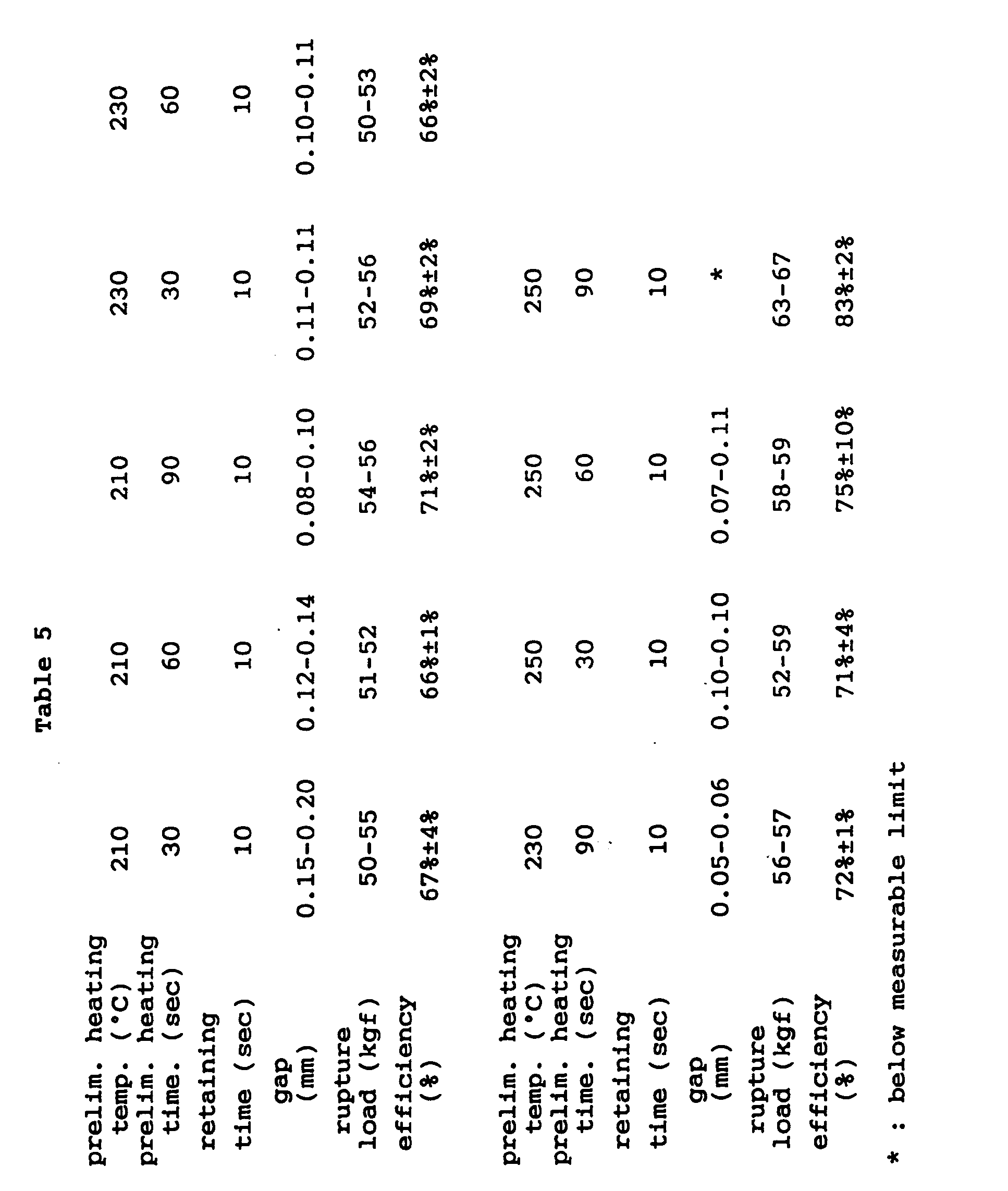
- According to this embodiment, because the
entire projection 1a melts and is thereafter upsetted as opposed to the conventional methods, there is no interface between the melted and unmelted parts, and a stable mounting strength can be obtained. Because the crimpingdie 3 is lower in temperature than the melting point of the resin material, the surface of the crimpedhead portion 1 a' solidifies before the interior thereof solidifies, there is no warping as opposed to the method of thermal crimping, and, instead, a pattern of internal stress is produced which tends to contract theprojection 1 a. Therefore, theplate member 2 is secured from two sides, and the two members can be joined together substantially without any gap between them. - According to this embodiment, a certain time period for preliminary heating is required, but, in practice, because the heating tool is not required to be brought into contact with the
member 1, it is possible to reduce the production cycle time by providing a plurality of stations each having a similar heating tool and heating each projection sequentially in these stations. - When the
plate member 2 is desired to be kept away from the influence of heat, an insulatingmember 6 may be placed between theheating tool 5 and theplate member 2 as shown in Figure 1. - Figures 3 and 4 are sectional views similarto Figures 1 and 2 showing a second embodiment of the present invention. In this embodiment, a
cavity 7a having a slightly larger diameter (with a radial gap of 0.3 mm in this experiment) than theresin projection 1a is centrally provided in the crimpingdie 7, and apiston 8 is slidably received in thiscavity 7a. This crimpingdie 7 is otherwise similar to the crimpingdie 3 of the first embodiment. - Now the procedure for mounting the
thermoplastic member 1 onto thetarget member 2 by using the method of crimping according to this embodiment is described in the following. First of all, in a similar manner as the first embodiment, with theprojection 1a of thethermoplastic resin member 1 passed through thehole 2a of thetarget member 2, theentire projection 1a is heated and melted with the thermal radiation from theheating tool 7. Then, as illustrated in Figure 3, theprojection 1 a is inserted in thecavity 7a of the crimpingdie 7 at the room temperature or a temperature lower than the melting point of the resin material, and thepiston 8 is moved in the direction indicated by arrow A so that theprojection 1a is pressurized and deformed into the prescribed crimped shape. - This embodiment is suitable for achieving a higher mechanical strength than the first embodiment. The
cavity 7a of the crimpingdie 7 controls the direction of the flow of the resin in the direction indicated by arrow E with the result that a lower part of theprojection 1a expands radially. - Table 6 shows the results of the test conducted on the thus crimped specimen to determine the tensile rupture strength of the crimped
head portion 1a' when thecylindrical member 1 is pulled in the direction indicated by arrow B while theplate member 2 is fixed. The gap between thecrimped head portion 1a' deformed from theprojection 1a and theplate member 2 was below the measurable range, and the tensile rupture strength was more than 80% of the theoretical value, which is comparable to the result obtained by insert molding. As can be seen from Figure 6 showing the thus produced crimpedhead 1a' in an enlarged sectional view, there were substantially no internal defects.
- According to the first embodiment using the crimping
die 3 not equipped with a piston, the pressurization by the crimpingdie 3 stops when it comes into contact with the target member (plate member), but the present embodiment allows the crimping process to be carried out with the pressure by thepiston 8 kept constant without regard to the fluctuations in the volume of theprojection 1a. Therefore, generations of burrs or flashes can be avoided, and any incomplete crimping can be prevented. Thus, even in mass production, the mechanical strength can be easily controlled within an acceptable range. - It is obvious that the shape of the resin material to be crimped may take other forms such as annular shapes as illustrated in Figures 7, 8 and 9. In Figure 7, numeral 11 denotes a thermoplastic resin member, numeral 12 denotes a target member or a plate member, numeral 16 denotes a crimping die, numeral 18 denotes a pressurization piston slidably received inside the crimping die, numeral 11a denotes a projection for crimping, and numeral 11a' denotes a crimped head portion after the molten resin has flown as indicated by arrow F.
- Figures 8(a) and 8(b) show a third embodiment of the present invention in which a metallic plate (second member) 19 is mounted on a rectangular box-shaped thermoplastic resin member (first member) having an open upper end.
Numeral 21 denotes a seal member received in anannular recess 20a provided in the upper peripheral surface of thefirst member 20. Thefirst member 20 is provided with fourprojections 22a on its upper surface. By crimping theseprojection 22a, by using a suitable heating tool and a crimping die, into the crimpedhead portions 22b according to the method of the present invention, themetallic plate 19 is subjected to a load directed as indicated by arrow C, and theseal member 21 is pressed into therecess 20a as shown in Figure 9 so as to achieve an air-tight chamber inside thefirst member 20. - As can be understood from the above description, according to the method of crimping of the present invention, after an entire portion of the thermoplastic resin member that is to be crimped is thermally melted or softened, the portion is deformed and crimped by using a crimping die having a die surface which is at a temperature lower the melting point of the thermoplastic resin. Therefore, the deformed portion is given with a uniform internal structure free from internal defects such as cracks and interfaces. Because the interior of the crimped portion remains to be hot as compared to the surface portion which is in contact with the crimping die during the crimping process, a certain pattern of internal stress is produced in the internal part which opposes the internal stress of the surface portion as the deformed portion cools and contracts. Therefore, warping of the crimped portion can be avoided, and the thermoplastic resin member can be mounted on the target member at a high mounting strength without complicating the fabrication process and without causing any reduction in the production efficiency.
- Although the present invention has been described in terms of preferred embodiments thereof, it is obvious to a person skilled in the art that various alterations and modifications are possible without departing from the scope of the present invention which is set forth in the appended claims.
Claims (7)
Applications Claiming Priority (2)
| Application Number | Priority Date | Filing Date | Title |
|---|---|---|---|
| JP90930/93 | 1993-03-24 | ||
| JP09093093A JP3421075B2 (en) | 1993-03-24 | 1993-03-24 | Method for caulking thermoplastic resin member and fastener |
Publications (3)
| Publication Number | Publication Date |
|---|---|
| EP0618061A2 true EP0618061A2 (en) | 1994-10-05 |
| EP0618061A3 EP0618061A3 (en) | 1995-02-22 |
| EP0618061B1 EP0618061B1 (en) | 1997-07-23 |
Family
ID=14012167
Family Applications (1)
| Application Number | Title | Priority Date | Filing Date |
|---|---|---|---|
| EP94302046A Expired - Lifetime EP0618061B1 (en) | 1993-03-24 | 1994-03-22 | Method for crimping a thermoplastic resin member and assembly including a thus crimped thermoplastic resin member |
Country Status (6)
| Country | Link |
|---|---|
| US (1) | US5695704A (en) |
| EP (1) | EP0618061B1 (en) |
| JP (1) | JP3421075B2 (en) |
| KR (1) | KR0184305B1 (en) |
| DE (1) | DE69404351T2 (en) |
| ES (1) | ES2105511T3 (en) |
Cited By (3)
| Publication number | Priority date | Publication date | Assignee | Title |
|---|---|---|---|---|
| EP0795925A2 (en) * | 1996-03-11 | 1997-09-17 | Nec Corporation | Patch antenna and method for making the same |
| EP0965400A2 (en) * | 1998-06-16 | 1999-12-22 | Emilio Pujadas Rabasso | Method and apparatus for riveting plastics parts |
| EP3103620A4 (en) * | 2014-07-11 | 2017-10-25 | Gunyang Itt Co., Ltd. | Vehicle door trim bonding device |
Families Citing this family (14)
| Publication number | Priority date | Publication date | Assignee | Title |
|---|---|---|---|---|
| US5980230A (en) * | 1997-04-11 | 1999-11-09 | Velcro Industries B.V. | Forming fastener products |
| KR20020062493A (en) * | 2001-01-22 | 2002-07-26 | 주식회사 센트랄 | Manufacturing method of ball joint for vehicle |
| DE60223225T2 (en) * | 2001-12-28 | 2008-07-31 | NGK Spark Plug Co., Ltd., Nagoya | Spark plug and method of manufacturing the spark plug |
| FR2854606B1 (en) * | 2003-05-06 | 2006-06-16 | Valeo Vision | ARRANGEMENT AND METHOD FOR COLD-RIDING ASSEMBLY OF TWO ELEMENTS OF A MOTOR VEHICLE LIGHTING EQUIPMENT |
| US6966109B2 (en) * | 2003-07-31 | 2005-11-22 | Eaton Corporation | Method for attaching and for ensuring orientation of components |
| JP5507408B2 (en) * | 2010-10-18 | 2014-05-28 | 小島プレス工業株式会社 | Cowl louver seal structure |
| JP5762028B2 (en) * | 2011-02-03 | 2015-08-12 | キヤノン株式会社 | Method for manufacturing liquid cartridge |
| AT513292B1 (en) * | 2012-09-03 | 2015-05-15 | Zizala Lichtsysteme Gmbh | Method for producing a positive connection |
| JP2014223770A (en) * | 2013-05-17 | 2014-12-04 | アイシン精機株式会社 | Heat caulking device and heat caulking method |
| JP6349573B2 (en) * | 2013-12-27 | 2018-07-04 | 三井金属アクト株式会社 | Striker |
| CN106573134B (en) * | 2014-06-20 | 2021-04-06 | 美德斯普瑞公司 | Spraying device and method for producing a spraying device and associated device |
| JP6222003B2 (en) | 2014-08-22 | 2017-11-01 | トヨタ自動車株式会社 | Part-to-part connecting structure and part-to-part connecting method |
| WO2018136090A1 (en) * | 2017-01-23 | 2018-07-26 | Hewlett-Packard Development Company, L.P. | Casings of electronic devices |
| DE102018002085A1 (en) * | 2018-03-15 | 2019-09-19 | bdtronic GmbH | Method and device for riveting components |
Citations (9)
| Publication number | Priority date | Publication date | Assignee | Title |
|---|---|---|---|---|
| GB555151A (en) * | 1942-02-02 | 1943-08-06 | Sidney John Henry Dex | Improvements relating to riveting |
| DE1479389A1 (en) * | 1965-10-30 | 1969-05-14 | Kalle Ag | Welding process and device for the production of continuous longitudinal weld seams in biaxially stretched film |
| GB1407213A (en) * | 1972-09-06 | 1975-09-24 | Chen Fung Woo | Welding heat fusible materials |
| DE3109500A1 (en) * | 1981-03-12 | 1982-10-07 | Repa Feinstanzwerk Gmbh, 7071 Alfdorf | Process and die for the plastic deformation of material which is deformable by pressure and heat |
| US4456451A (en) * | 1982-09-29 | 1984-06-26 | Vosper George W | Apparatus for shaping rope ends |
| GB2173139A (en) * | 1985-03-18 | 1986-10-08 | Ladney M Jr | Method and apparatus for staking |
| US5018957A (en) * | 1990-05-25 | 1991-05-28 | J R Automation Technologies, Inc. | Hot staking machine |
| US5095606A (en) * | 1990-08-13 | 1992-03-17 | Hewlett-Packard Company | Device and method for heat and pressure forming stakes |
| US5187863A (en) * | 1991-03-27 | 1993-02-23 | E. I. Du Pont De Nemours And Company | Method and device for connecting a connector to a board |
Family Cites Families (13)
| Publication number | Priority date | Publication date | Assignee | Title |
|---|---|---|---|---|
| US3754319A (en) * | 1972-02-18 | 1973-08-28 | Camillus Cutlery Co | Method of fabricating a knife handle |
| US4130623A (en) * | 1976-04-12 | 1978-12-19 | General Motors Corporation | Method of embossing |
| FR2409802A1 (en) * | 1977-11-28 | 1979-06-22 | Socapex | DEVICE FOR CRIMPING THE END OF OPTICAL FIBER BEAMS |
| US4340560A (en) * | 1980-01-04 | 1982-07-20 | Timex Corporation | Method for making a rotor assembly |
| DE3612518A1 (en) * | 1986-04-14 | 1987-10-15 | Rxs Schrumpftech Garnituren | METHOD FOR PRODUCING A PLASTIC PART WITH MOLDED MEMORY, AND DEVICE FOR CARRYING OUT THIS METHOD, AND PLASTIC PARTS MANUFACTURED BY THIS METHOD |
| JPH01215515A (en) * | 1988-02-24 | 1989-08-29 | Polyplastics Co | Manufacture of rack gear of thermoplastic resin and manufacturing device thereof |
| CA1328158C (en) * | 1988-05-11 | 1994-04-05 | Toshiyuki Kanai | Multi-injection molded body, a method of molding for the same, and a multi-injection molding machine |
| US4859378A (en) * | 1988-10-28 | 1989-08-22 | Branson Ultrasonics Corporation | Method of ultrasonically assembling workpieces |
| US5106566A (en) * | 1988-10-31 | 1992-04-21 | Dowbrands Inc. | Forming a reclosable closure for a thermoplastic container |
| DE3911746A1 (en) * | 1989-04-11 | 1990-10-18 | Philips Patentverwaltung | TECHNICAL DEVICE, IN PARTICULAR ELECTROMECHANICAL DRIVE FOR MOVING INFORMATION CARRIERS, AND METHOD FOR PRODUCING FUNCTIONAL PARTS ON A SUPPORTING PLATE OF THE DEVICE |
| FR2665119A1 (en) * | 1990-07-30 | 1992-01-31 | Cebal | Method of obtaining recessed marks or outlines on a plastic or metal-plastic tubular sheet or part and its use in the manufacture of a flexible tube |
| JPH0741675B2 (en) * | 1990-10-04 | 1995-05-10 | 三菱電機エンジニアリング株式会社 | Heat staking device |
| GB9103378D0 (en) * | 1991-02-19 | 1991-04-03 | British Aerospace | Progressive moulding and curing of composite materials |
-
1993
- 1993-03-24 JP JP09093093A patent/JP3421075B2/en not_active Expired - Lifetime
-
1994
- 1994-03-17 KR KR1019940005363A patent/KR0184305B1/en not_active IP Right Cessation
- 1994-03-22 ES ES94302046T patent/ES2105511T3/en not_active Expired - Lifetime
- 1994-03-22 DE DE69404351T patent/DE69404351T2/en not_active Expired - Lifetime
- 1994-03-22 EP EP94302046A patent/EP0618061B1/en not_active Expired - Lifetime
-
1996
- 1996-03-04 US US08/610,767 patent/US5695704A/en not_active Expired - Lifetime
Patent Citations (9)
| Publication number | Priority date | Publication date | Assignee | Title |
|---|---|---|---|---|
| GB555151A (en) * | 1942-02-02 | 1943-08-06 | Sidney John Henry Dex | Improvements relating to riveting |
| DE1479389A1 (en) * | 1965-10-30 | 1969-05-14 | Kalle Ag | Welding process and device for the production of continuous longitudinal weld seams in biaxially stretched film |
| GB1407213A (en) * | 1972-09-06 | 1975-09-24 | Chen Fung Woo | Welding heat fusible materials |
| DE3109500A1 (en) * | 1981-03-12 | 1982-10-07 | Repa Feinstanzwerk Gmbh, 7071 Alfdorf | Process and die for the plastic deformation of material which is deformable by pressure and heat |
| US4456451A (en) * | 1982-09-29 | 1984-06-26 | Vosper George W | Apparatus for shaping rope ends |
| GB2173139A (en) * | 1985-03-18 | 1986-10-08 | Ladney M Jr | Method and apparatus for staking |
| US5018957A (en) * | 1990-05-25 | 1991-05-28 | J R Automation Technologies, Inc. | Hot staking machine |
| US5095606A (en) * | 1990-08-13 | 1992-03-17 | Hewlett-Packard Company | Device and method for heat and pressure forming stakes |
| US5187863A (en) * | 1991-03-27 | 1993-02-23 | E. I. Du Pont De Nemours And Company | Method and device for connecting a connector to a board |
Non-Patent Citations (1)
| Title |
|---|
| PATENT ABSTRACTS OF JAPAN vol. 16, no. 422 (M-1305) 4 September 1992 & JP-A-04 142 919 (SAITO TATSUYA) * |
Cited By (7)
| Publication number | Priority date | Publication date | Assignee | Title |
|---|---|---|---|---|
| EP0795925A2 (en) * | 1996-03-11 | 1997-09-17 | Nec Corporation | Patch antenna and method for making the same |
| EP0795925A3 (en) * | 1996-03-11 | 1998-01-14 | Nec Corporation | Patch antenna and method for making the same |
| US5977710A (en) * | 1996-03-11 | 1999-11-02 | Nec Corporation | Patch antenna and method for making the same |
| AU726672B2 (en) * | 1996-03-11 | 2000-11-16 | Nec Corporation | Patch antenna and method for making the same |
| EP0965400A2 (en) * | 1998-06-16 | 1999-12-22 | Emilio Pujadas Rabasso | Method and apparatus for riveting plastics parts |
| EP0965400A3 (en) * | 1998-06-16 | 2000-11-22 | Emilio Pujadas Rabasso | Method and apparatus for riveting plastics parts |
| EP3103620A4 (en) * | 2014-07-11 | 2017-10-25 | Gunyang Itt Co., Ltd. | Vehicle door trim bonding device |
Also Published As
| Publication number | Publication date |
|---|---|
| US5695704A (en) | 1997-12-09 |
| DE69404351T2 (en) | 1998-01-08 |
| KR0184305B1 (en) | 1999-05-15 |
| EP0618061B1 (en) | 1997-07-23 |
| JPH06270263A (en) | 1994-09-27 |
| KR940021237A (en) | 1994-10-17 |
| JP3421075B2 (en) | 2003-06-30 |
| EP0618061A3 (en) | 1995-02-22 |
| DE69404351D1 (en) | 1997-09-04 |
| ES2105511T3 (en) | 1997-10-16 |
Similar Documents
| Publication | Publication Date | Title |
|---|---|---|
| EP0618061A2 (en) | Method for crimping a thermoplastic resin member and assembly including a thus crimped thermoplastic resin member | |
| US4416716A (en) | Method of producing interior material of corrugated cardboard | |
| US5096525A (en) | Apparatus and method for forming and bonding a thermoplastic part from thermoplastic blanks | |
| US5597523A (en) | Molding apparatus and method in which a mold cavity gasket is deformed by separately applied pressure | |
| JPH07195392A (en) | Production of insert molded form having fluororesin as facing | |
| CN101663156B (en) | Method of fastening first and second thermoplastic parts, and two-part assembly | |
| JP2004058391A (en) | Thermally caulking structure and method for thermally caulking and connecting | |
| US5026267A (en) | Apparatus for forming thermoplastic material | |
| US4072817A (en) | Method of making semi-conductor mounts | |
| JP2000025116A (en) | Hot plate welding method and supporting jig necessary therefor | |
| JPH11201227A (en) | Base isolation rubber body for base isolation device and manufacture thereof | |
| KR102236180B1 (en) | mold for press forming of car interior material and method of forming the same | |
| JPH0212611A (en) | Manufacture of magnetic head | |
| JP3381000B2 (en) | Thermoforming method | |
| JP3141598B2 (en) | Method of manufacturing friction pad for disc brake | |
| JPH05296349A (en) | Manufacture of divided boot for universal joint | |
| JPH0149615B2 (en) | ||
| JPH08132532A (en) | Method and apparatus for caulking plastic member | |
| JPH03106521A (en) | Joining method for two parts | |
| JP2008121899A (en) | Electric welding type plastic pipe joint and manufacturing method for it | |
| JPH01241330A (en) | Blank for superplastic forming | |
| JPS6327573B2 (en) | ||
| JPS6111206A (en) | Compression molding and mold therefor | |
| JPH06254963A (en) | Deposition of plastic part and plastic part | |
| JPS60190653A (en) | Manufacturing method of synthetic resin float for carburetor |
Legal Events
| Date | Code | Title | Description |
|---|---|---|---|
| PUAI | Public reference made under article 153(3) epc to a published international application that has entered the european phase |
Free format text: ORIGINAL CODE: 0009012 |
|
| AK | Designated contracting states |
Kind code of ref document: A2 Designated state(s): DE ES GB |
|
| PUAL | Search report despatched |
Free format text: ORIGINAL CODE: 0009013 |
|
| AK | Designated contracting states |
Kind code of ref document: A3 Designated state(s): DE ES GB |
|
| 17P | Request for examination filed |
Effective date: 19950301 |
|
| 17Q | First examination report despatched |
Effective date: 19960105 |
|
| GRAG | Despatch of communication of intention to grant |
Free format text: ORIGINAL CODE: EPIDOS AGRA |
|
| GRAH | Despatch of communication of intention to grant a patent |
Free format text: ORIGINAL CODE: EPIDOS IGRA |
|
| GRAH | Despatch of communication of intention to grant a patent |
Free format text: ORIGINAL CODE: EPIDOS IGRA |
|
| GRAA | (expected) grant |
Free format text: ORIGINAL CODE: 0009210 |
|
| AK | Designated contracting states |
Kind code of ref document: B1 Designated state(s): DE ES GB |
|
| REF | Corresponds to: |
Ref document number: 69404351 Country of ref document: DE Date of ref document: 19970904 |
|
| REG | Reference to a national code |
Ref country code: ES Ref legal event code: FG2A Ref document number: 2105511 Country of ref document: ES Kind code of ref document: T3 |
|
| PLBE | No opposition filed within time limit |
Free format text: ORIGINAL CODE: 0009261 |
|
| STAA | Information on the status of an ep patent application or granted ep patent |
Free format text: STATUS: NO OPPOSITION FILED WITHIN TIME LIMIT |
|
| 26N | No opposition filed | ||
| REG | Reference to a national code |
Ref country code: GB Ref legal event code: IF02 |
|
| PGFP | Annual fee paid to national office [announced via postgrant information from national office to epo] |
Ref country code: ES Payment date: 20130314 Year of fee payment: 20 Ref country code: GB Payment date: 20130320 Year of fee payment: 20 Ref country code: DE Payment date: 20130320 Year of fee payment: 20 |
|
| REG | Reference to a national code |
Ref country code: DE Ref legal event code: R071 Ref document number: 69404351 Country of ref document: DE |
|
| REG | Reference to a national code |
Ref country code: GB Ref legal event code: PE20 Expiry date: 20140321 |
|
| PG25 | Lapsed in a contracting state [announced via postgrant information from national office to epo] |
Ref country code: GB Free format text: LAPSE BECAUSE OF EXPIRATION OF PROTECTION Effective date: 20140321 Ref country code: DE Free format text: LAPSE BECAUSE OF EXPIRATION OF PROTECTION Effective date: 20140325 |
|
| REG | Reference to a national code |
Ref country code: ES Ref legal event code: FD2A Effective date: 20140926 |
|
| PG25 | Lapsed in a contracting state [announced via postgrant information from national office to epo] |
Ref country code: ES Free format text: LAPSE BECAUSE OF EXPIRATION OF PROTECTION Effective date: 20140323 |