EP0618022A1 - Automatic system for selecting and feeding preoriented rivets to riveting machines - Google Patents
Automatic system for selecting and feeding preoriented rivets to riveting machines Download PDFInfo
- Publication number
- EP0618022A1 EP0618022A1 EP94830116A EP94830116A EP0618022A1 EP 0618022 A1 EP0618022 A1 EP 0618022A1 EP 94830116 A EP94830116 A EP 94830116A EP 94830116 A EP94830116 A EP 94830116A EP 0618022 A1 EP0618022 A1 EP 0618022A1
- Authority
- EP
- European Patent Office
- Prior art keywords
- rivets
- rivet
- magazine
- preoriented
- fasteners
- Prior art date
- Legal status (The legal status is an assumption and is not a legal conclusion. Google has not performed a legal analysis and makes no representation as to the accuracy of the status listed.)
- Ceased
Links
Images


Classifications
-
- B—PERFORMING OPERATIONS; TRANSPORTING
- B23—MACHINE TOOLS; METAL-WORKING NOT OTHERWISE PROVIDED FOR
- B23P—METAL-WORKING NOT OTHERWISE PROVIDED FOR; COMBINED OPERATIONS; UNIVERSAL MACHINE TOOLS
- B23P19/00—Machines for simply fitting together or separating metal parts or objects, or metal and non-metal parts, whether or not involving some deformation; Tools or devices therefor so far as not provided for in other classes
- B23P19/001—Article feeders for assembling machines
-
- B—PERFORMING OPERATIONS; TRANSPORTING
- B21—MECHANICAL METAL-WORKING WITHOUT ESSENTIALLY REMOVING MATERIAL; PUNCHING METAL
- B21J—FORGING; HAMMERING; PRESSING METAL; RIVETING; FORGE FURNACES
- B21J15/00—Riveting
- B21J15/10—Riveting machines
- B21J15/30—Particular elements, e.g. supports; Suspension equipment specially adapted for portable riveters
- B21J15/32—Devices for inserting or holding rivets in position with or without feeding arrangements
-
- Y—GENERAL TAGGING OF NEW TECHNOLOGICAL DEVELOPMENTS; GENERAL TAGGING OF CROSS-SECTIONAL TECHNOLOGIES SPANNING OVER SEVERAL SECTIONS OF THE IPC; TECHNICAL SUBJECTS COVERED BY FORMER USPC CROSS-REFERENCE ART COLLECTIONS [XRACs] AND DIGESTS
- Y10—TECHNICAL SUBJECTS COVERED BY FORMER USPC
- Y10S—TECHNICAL SUBJECTS COVERED BY FORMER USPC CROSS-REFERENCE ART COLLECTIONS [XRACs] AND DIGESTS
- Y10S221/00—Article dispensing
- Y10S221/01—Storage retrieval
Abstract
The system foresees to equip each riveting machine (3) with a buffer magazine (2) comprising a tube bundle (26) inside which each single tube element (29) is containing a certain amount of preoriented rivets or like fasteners one by one quickly deliverable to the riveting machine and to place on the floor, in a stationary position, a feed station (1) in charge to keep refurbished all the buffer magazines (2) connected to it. Each buffer magazine (2) contains the entire inventory of rivet used by the machine and it accomplish the task to quickly satisfay any request from the riveting machine; the floor mounted feed station (1) accomplish the task to maintaining refilled any buffer magazines. The feed station (1) is activated when the rivet level of a tube element (29) inside a buffer (2) reaches the minimum level.
Description
- The present invention relates to an automatic assembly systems and particularly to a system for the selection and the delivery of preoriented rivets or like fasteners to one or more riveting machines.
- The procedure of assembling parts by means of riveting is largely used in the industry; in particular in the aerospace industry. During the evolution of this technology, a large number of automatic riveting machines have been developed, which according to the parts to be assembled, are able to install different kinds of rivets or like festeners and for each kind of them, to finalize the choice of different lengths depending upon the thickness of the sheets to be jointed.
- Rivets or like fasteners are usually supplied from a suitable rivet feeding system capable to select and send, time by time, to the riveting machine the right kind and length of requested rivet.
- With the development of continuous numeric control (CNC) the later automatic riveting machines are capable to assemble a larger number of different parts and, for each of them, to storage the program which assigns the position of each rivet to be installed. The machines are as well able to accurately finalize the correct call of the right kind and length of the rivet to be installed.
- Typically the rivet kind is assigned by the designer and memorized inside the program while the length is chosen upon measuring, time by time, the thickness of the parts to be connected together.
- Rivets are consequently requested with an unpredictable sequence and they must be delivered in a very short time in order to avoid the cycle time to be slowed down.
- Several automatic rivet feed systems are known, in which all rivets of the same kind and same length (identical) are storaged inside a preassigned vibratory bowl which provides orientation and accumulation of the rivets inside a track, usually horizontal, whereby rivets are withdrawn one at a time and pneumatically transferred via tube to the riveting machine.
- In addition to such systems, other automating riveting magazine means are known such as spirals or cassettes or other whereas the different rivets are inserted and preoriented inside a "cartridge-type" magazine. Such magazines feature a certain capacity and usually are mounted close to the riveting machine.
- Both these approaches to the problem of automatically feeding a riveting machine by delivering to it, one by one, a preoriented rivet belonging to a certain inventory of available rivets, suffer several heavy constraints and/or limitations.
- In the solution with vibrating bowl, each bowl is dedicated to a precise kind and length of the rivet and such solution is consequently very expensive and bulky. In fact, it is sufficient to think to a system able to handle five different kinds of rivets and for each of them at least ten different grip lengths to have an idea of costs and size involved. Furthermore, a feed station featuring fifty or more bowls cannot be mounted a board of the machine for problems of weight an size and consequently it needs to lie on the floor and to be connected via tube to the riveting machine with a related performance drop in terms of delivery time.
- The other solutions with "cartridge magazine" are on one hand more compact, but on the other hand they need continuous supervision to replace empty magazines and they involve as well cost aggravation related to the magazine preparation .
- The main object of the present invention is to provide an inexpensive and reliable system for selecting and automatic feeding pre-oriented rivets to the automatic riveting machine.
- Another object of the present invention is to provide a system capable to perform a particularly short average rivet delivery time to the riveting machine, the term "average time" meaning the time from when the machine forwards the rivet call to the instant when the machine receives the desired rivet.
- A further object of the present invention is to provide a system capable to feed several riveting machines simultaneously.
- Still a further object of the present invention is to provide a system extremely compact and efficient even in applications where it is necessary to automatically handle a very large number of different rivets (f.e. one hundred or more).
- More in particular the system for the automatic selection, orientation and feeding of rivets or like fasteners to one or more riveting machines fed from a main feed station operating in a remote and stationary position, comprises:
- a mobile buffer magazine for each riveting machine, intended to receive, one by one, the desired rivet requested from the machine and comprising a plurality of individual magazine means each one intended to contain a plurality of preoriented rivets of the same kind and the same grip length;
- a plurality of rivet orienting means each able to supply in a preoriented and organized manner rivets from an unorganized stack of rivets and supplying them one by one;
- first transporting means for transferring rivets or like fasteners from the main service station to said mobile buffer magazine;
- second transporting means for transferring rivets from the mobile buffer magazines to the related automatic riveting machine;
- first positioning means for positioning the outlet end of each of said first transporting means in coaxial alignment with the inlet end of each individual magazine means belonging to said mobile buffer magazine;
- second positioning means for positioning the inlet end of each of said second transporting means in coaxial alignment with the outlet end of each one of the individual magazine means of said mobile buffer magazine;
- The present invention will now be described in greater detail in connection with a preferred embodiment given by way of an example and in conjunction with the accompanying drawings, in which:
- Fig. 1 is a schematic illustration showing how the system according to the present invention operates;
- Fig. 2 shows a typical family of utilized rivets;
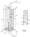
- Fig. 3 is a schematic section of the mobile buffer magazine;
- Fig. 4 is a prospectic view of the device for the selection and interconnection of the tubes according to a preferred embodiment;
- Fig.5 is a schematic top view of the mobile buffer magazine;
- Fig 6 is a cross section of a typical transporting means for rivets or like fasteners;
- Fig. 7 schematically shows the typical arrangement of the main feed station according to the most complete embodiment; and
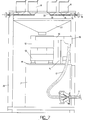
- Fig. 8 shows schematically a typical application of the system.
- In Fig. 1 there are schematically illustrated the
main feed station 1, themobile buffer magazine 2, theautomatic riveting machine 3, the related rivetinghead 4, the rivet transporting means 7,20 and 22 connecting themain service station 1 to thebuffer magazine 2, the control means 5 and thecables 6 connecting the latter to the controlled utilities. The same Figure shows, inside themain feed station 1 is shown a plurality ofhoppers 8 all containing rivets of the same kind but with each separate hopper containing rivets of different grip length, the shuttle valve 9 for the opening and closing of thehoopers 8, the rivet orienting means 11 and thetransfer tube 17. Eachorienting device 11 comprises abowl 12 and arelated vibrating device 13, atrack 14 and therelated vibrating device 15 and anescapement 16 whilenumeral 10 indicates the tubes connecting eachhopper 8 to thesame bowl 12. In the same Figure, the rivet transfer tube connecting theescapement 16 to thedistributor 25 comprises thetube sections booster device 18, aselecting device 19 and deceleratingdevice 21 are interposed. In the same Figure there is shown how theselectors 19 allow theunique service station 1 to be connected to a plurality of mobile buffer magazines, in the Figure the references 27 and 28 indicating the direction oftubes 20 towards two additional buffer magazines (not shown in the Figure). - Still in Figure 1, there are shown the main element of the
buffer magazine 2 and particularly the upper selectingdevice 23 equipped with the mobile transverse 24 anddistributor 25, thetube bundle 26 comprising a plurality ofsingle tubing elements 29 placed in an organized arrangement, the lower selectingdevice 30 equipped with the mobile transverse 31. and adistributor 32. Furthermore Figure 1 shows the rivet receivingunit 34 embodied inside the rivetinghead 4 and thetubes 33 dedicated to transfer the rivets or like fasteners from themobile buffer magazine 2 to the rivetinghead 4. - In Figure 2 two different kinds of
rivets shortest rivet 39, thelongest rivet 43 and allother rivets References rivet kind 36, respectively while for sake of simplicity the intermediate lengths are not shown. - In Figure 3 the components of
mobile buffer magazine 2 are schematically represented. Among them it can be seen atube 22 coming from thefeed station 1 of Figure 2, the upperselecting device 23, thetube bundle 26, thelower selecting device 30 and thetube 33 outgoing towards the rivetinghead 4 of Figure 1. Inside the tube bundle a plurality ofvertical tubes 29 are shown and four of them 46,42 and 49 are represented in cross section and show therivets rivets
The same Figure 3 a rivet selector (escapement) 50 shows located at the lower bottom end of eachtube 29 belonging totube bundle 26; inside the escapement two different opening-closing devices distributor 32 equipping thelower selecting device 30, but, as further explained in greater detail, one single pair of actuators is able to drive theescapement 50 of eachtube 29. - Figure 4 is a prospective view of the preferred embodiment of the upper selecting
device 23 and shows thetube carrier 58, thehousing 59 fortubes 22 of Figure 1, thetraverse 55 on which thetube carrier 58 horizontally slides along the direction Y, therails traverse 55 transversely slides along the direction X and theframe 60. - For sake of simplicity the related
lower selecting device 30 is not shown since it is identical to the upper one but simply mounted upside down at the bottom end of thesame frame 60. - Figure 5 is a top view of the buffer magazine which, in addition to afore mentioned elements in Figure 4, shows a tube bundle comprising one hundred
tubes 29 arranged according to a 10x10 array. It must be noted that thereceiving head 58 is prearranged for fourdifferent tubes 22 and each of them can be positioned in coaxial alignment with any one of the one hundred underlayingtubes 29 so that when for example it is necessary to aligntube 22 located in theposition 63 of thehead 58 withtube 29 located in theposition 62 inside the buffer magazine, then thetube 22 which is located in theposition 59 of thehead 58 necessarily will occupy theposition 61. - In order to establish whichever possible combination among
tubes 22 andtubes 29 it is consequently necessary to foresee one empty space perimetrally around the tube bundle and to enlarge consequently both theframe 60 and thetraverse 55 of theselecting devices - Figure 6 shows the typical rivet transporting line comprising an
orienting device 14, therelated escapement device 16, thefirst tube section 17, thebooster device 18, asecond tube section 7, aselecting device 19, threeoutgoing tubes deceleration device 64 and the last tube section 22a which reaches the upper selectingdevice 23 inside themobile buffer magazine 2. - Further in Figure 6 there are shown some details inside the
devices device 18 theinlet air conduit 69, theannular distribution chamber 67 and theinclined holes 68 for air injection inside the tube. Arranged inside thedevice 19 is thetube housing 70 receiving asingle tube 7 whereas theshuttling drawer 70 is arranged inside the distributor body with one ormore tubes 20 connected thereon, for example 20A,20B and 20C, each of them directed towards a different mobile buffer magazine. Inside thedevice 21 thecylindrical body 64 is shown, the inlet of which is connected to one end oftube 20A while the outlet is connected to one end oftube 22A, a plurality ofsmall holes 66 radially located and an outer cylindrical sleeve acting as an exhaust flow regulator (to partially close holes 66). The same Figure shows as well themagnetic sensors 72 intended to provide feed back for correct rivet transit inside the tube. - Figure 7 schematically shows the arrangement of the main components of a typical modular unit inside the main rivet feed station. In particular each unit comprises the
hoppers 8 with their funnel shapedend 73, theshuttle valve 74, the relatedpneumatic actuator 73 comprising the knob 76 (to override the pneumatic actuator) the quadrangular shapedfunnel 77 and the orienting means 11 previously shown in Figure 1. - The same Figure shows as well the supporting
element 71 of the orienting means 11 and the supportingmeans 78 for thehoppers 8. It is important to observe that each different rivet requires its owndedicated hoppers 8 while all rivets of the same kind, regardless of their length, are oriented and sent one by one from a single orienting means 11. The arrangement within the main service station consequently foresee to gather together allhoppers 8 containing rivets of different grip length but of the same kind. The group of hoppers containing rivets of the same kind is located above a single orienting means 11 suitable to orient that particular kind of rivet. - Of course, the
main feed station 1 will comprise as many modular units as are the differents kinds of rivet handled and units number is not related to different grip lengths since this is only effect the number of hoppers integrated and not the number of modular units integrated. - Figure 8 shows a front view and a top view of a typical application of the present invention whereas the system is mounted a board of an automatic riveting machine comprising in this particular case a robot adapted to position and orient the riveting head. This Figure shows the
main feed station 1 located on the floor in a stationary position, themobile buffer magazine 2, therivets transporting means - The same Figure shows as well the main robot components such as the
main bed section 80, themobile column 81, the translatingram 82, the operatinghead 83 and the main robot moving direction X, Y, Z and A. - During normal operation in the automatic mode, the riveting machine is able to exactly finalize, one at a time, kind and length of the rivet to be installed. The task to quickly deliver to the riveting machine one specifically requested rivet at a time is carried out by the
mobile buffer magazine 2 inside which the entire inventory of preoriented rivet or like fasteners is contained. Inside the buffer magazine, usually located a board of the riveting machine, at a small distance from the riveting head, in an organized manner placed a plurality ofvertical tubes 29 inside which a limited amount of preoriented identical rivets are stacked one on top of the other. For each different kind of rivets a certain number of vertical tubes is foreseen which have an inner diameter slightly higher than the maximum diameter of the head of that particular kind of rivet; at least one of these vertical tubes is dedicated to each different grip length of rivets of the same kind so that, inside the buffer magazine, there is at least a number of tubes equal to the number of different rivets inside the inventory of rivets necessary to the riveting machine to perform the assembly cycles. - Being said tubes capacity necessarily limited, more than one tube can be dedicated to accumulate rivets of the same kind and length, this being particularly convenient for frequently called rivets.
- All vertical tubes inside the buffer magazine are kept normally full so that the buffer magazine is, in every instant, able to satisfy the rivet calls of the riveting machine.
- In case it is necessary to deliver frozen rivets to the riveting machine, some or all of the vertical tubes can be thermically insulated and kept chilled, for example by liquid nytrogen injection.
- The task of refilling the buffer magazines is carried out by the
main feed station 1 which keeps the rivet level above the minimum storage level inside all buffer magazines. Whenever in fact, rivets inside one of thetubes 29 reach the minimum storage level, themain service station 1 starts to refill that tube sending in sequence a certain number of preoriented rivets identical to the one contained inside it. - This can happen with two different procedures according to the alternative arrangement of the
main feed station 1. - The first option foresees a rivet feed station containing an orienting means 11, for example a vibrating bowl for each different kind and or length of rivet and from which it is directly possible to withdraw, one by one, the preoriented rivets necessary to refill the
empty tubes 29 from the minimum level to the maximum level. In this case each orienting means 11 is permanently dedicated to a specific kind and length of rivets. - A second option foresees a rivet feed station containing a certain amount of every different rivets or like fasteners belonging to the inventory, storaged in heaps inside
suitable hoppers 8. - The hoppers containing rivets of the same kind but of different grip length, are gathered and placed above a single orienting means 11 suitable to orient rivets of the same kind regardless of their length.
- A plurality of
tubes 10 rather than a single funnel are placed between thehoppers 8 and the orienting means 11 so that, by gravity, it is possible to transfer the entire contents of one of the hoppers inside the same orienting means 11. Thehoppers 8 contain a preweigthed and pre-counted amount of rivets and they are kept filled by an operator; the orienting means 11 is normally empty and off. - That is to say, that at least one hopper 8 (containing rivets in heaps) and one tube 29 (containing rivet selected and preoriented) are univocally preassigned to each different rivet and both are kept normally full.
- During the automatic operating cycle the riveting machine forwards its instantaneous rivet request in terms of desired kind and length.
With reference to Figures 1 and 3, for each different rivet selection, at least onetube 29 is univocally dedicated inside themobile buffer magazine 2 and oneparticular tube 33 is as well associated. Consequently the selecteddevice 30 moves its own axes X and Y in order to bring in coaxial alignment the selectedtube 33 with thetube 29 which contains the desired rivets. - At this point a first actuator, located inside the
head 58 of thedevice 30, activates the opening of thefirst device 52 causing the release of a single rivet, more precisely the one resident inside theexpulsion chamber 54 of Figure 3 which, simply for gravity or pneumatically pushed, enters theunderlying tube 33 without loosing the orientation and then reaches theriveting head 4. Once the delivery of the rivet is accomplished thedevice 52 is closed while asecond opening device 51 is opened allowing the above rivet column to discend. Oncerivet 53reaches chamber 54, thedevice 51 is closed and theescapement 50 is consequently ready for next delivery. - As the automatic riveting machine continues the cycle dictating its rivet requests, the selecting
device 30, controlled by the riveting machine continues to withdraw fromtubes 29 the requested rivet and consequently the rivet level inside each one of them is decreasing. - When it occurs that one out of all
tubes 29 reaches the minimum storage level, the main feed station starts the refilling process. It must be observed that said minimum level is directly detected by a sensor or it is alternatively indirectly provided by keeping track of the number of rivets withdrawn so that the control units can reliably supervise the rivet level inside each one oftubes 29 ofmagazine 26. - The refilling cycle starts with a positioning of the selecting
device 23 during which the selectedtube 22, suitable for transporting rivets contained inside thespecific tube 29 to be refilled, is brought in coaxial alignment with the latter, so that the rivets sent from the main feed station can be inserted therethrough. - Once said positioning has been accomplished the control unit commands the opening of the shuttle valve 9 of
hoppers 8 containing rivets identical to the ones contained inside theempty tube 29 to be refilled. The rivets fall insidetube 10 and then reachbowl 10 where the orienting cycle is started. All identical rivets are organized in line inside atrack 14 and then in a sequence of one by one, are released in preoriented relationship insidetube 17. Each of them reachesbooster device 18 which applies a pneumatic thrust, then thedevice 19 which directs them towards the selected buffer magazine then thedevice 21 which slows the rivets down allowing them to enter theunderlying tube magazine 29 with limited speed. This continues until the entire amount of rivets originally contained inhopper 8 is sent to thetube 29; it must be noted that the refilling cycle is carried out while riveting it is operating and the number of rivets per minute transferred by the rivet feed station to the buffer is far higher then the rivet withdrawn from the buffer by the riveting machine. - The refilling cycle is accomplished and starts again once the rivet level inside another
tube 29 becomes slower than the minimum level. If this occurs while the previous refilling cycle for anothertube 29 is not finished yet, the request goes in waiting list and it is carried out once the previous one is accomplished. - The system is then ready for the refilling of the
next tube 29 requiring assistance. Obviously the capacity of thetube 29 to be refilled is equal or greater than the capacity of thecorresponding hopper 8. - From what it has been described, it is clear how the system of the selection and the automatic delivery of rivets according to the present invention represents a considerable progress against previous state of the art since it allows the following advantages to be attained:
- The system, specially in the application in which a large amount of different rivet kinds and lengths need to be handled, is less expensive.
- The system can simultaneously feed more than one riveting machine.
- The system features a very short rivet delivery time regardless of the number of different rivets or like fasteners to be handled.
- The system is more compact and more reliable compared to a previous technology handling the same amount of different rivets.
said plurality of rivet orienting means, and positioning means being under control of a same control means.
Claims (14)
1) System for selecting and automatic feeding preoriented rivets or like fasteners to one or more riveting machines fed from a main feed station operating in a remote stationary position, comprising:
- a mobile buffer magazine (2) for each riveting machine (3), dedicated to receive, one by one, the desired rivet requested from the machine and comprising a plurality of individual magazine means (29) each intended to contain a plurality of preoriented rivets of the same kind and the same grip length;
- a plurality of rivet orienting means (11) each able to supply, in a preoriented and organized manner, rivets from an unorganized stack of rivet and supplying them one by one;
- first transporting means (17,7,20 and 22) for transferring rivets or like fasteners from the main feed station (1) to said mobile buffer magazine (2);
- second transporting means (33) for transferring rivets from the mobile buffer magazines (2) to the related automatic riveting machine (3);
- first positioning means (23) for positioning the outlet end of each of said first transporting means (22) in coaxial alignment with the inlet end of each individual magazine means (29) belonging to said mobile buffer magazine (2);
- second positioning means (30) for positioning the inlet end of each of said second transporting means (33) in coaxial alignment with the outlet end of each one of the individual magazine means (29) of said mobile buffer magazine (2); said plurality of rivet orienting means (11), and positioning means (23,30) being under control of a same control means.
2) System for selecting and automatic feeding preoriented rivets or like fasteners to one or more riveting machines according to claim 1 wherein the individual magazine means (29) inside said mobile buffer magazine (2) are linear tubes arranged in an organized parallelepiped-shaped tube bundle (26).
3) System for selecting and automatic feeding preoriented rivets or like fasteners to one or more riveting machines according to claim 1 and 2 wherein each said individual magazine means (29) comprises a double opening-closing device (50) located at the bottom end and capable to withstand the weight of the above laying column of preoriented rivet (53) stacked one on top of the other and release one rivet at a time upon command given by the control unit (5).
4) System for selecting and automatic feeding preoriented rivets or like fasteners to one or more riveting machines according to claim 1 wherein said transporting means are flexible tubes (17,7,20 and 22) each one of them featuring an internal diameter that allows the kind of rivet to which the tube is dedicated to travel inside it pneumatically pushed without loosing the orientation originally impressed during its first insertion inside the tube itself regardless of the grip length and as long as its length is greater than the rivet head diameter.
5) System for selecting and automatic feeding preoriented rivets or like fasteners to one or more riveting machines according to claims 1 and 4 wherein said first transporting means (17,7) between said floor mounted main feed station (1) and said mobile magazine (2) comprises a booster device (18) interposed and dedicated to transfer energy to the rivet in order to maintain a desired target speed inside the tube, said energy being applied by injecting inside the tube compressed air behind the travelling rivet with suitable air pressure and air flow.
6) System for selecting and automatic feeding preoriented rivets or like fasteners to one or more riveting machines according to claims 1 wherein said first transporting means (20,22) from said floor mounted feed station (1) and said mobile magazine (2) comprises an interposed decelerating device (21) dedicated to slow down the rivet speed, said device presenting a cylindrical body (64) having a coaxial hole of the same diameter as the connected tube means, a plurality of little exhaust holes (66) radially displaced and an exhaust flow regulator means (65) for the partial occlusion of said exhaust holes (66), said decelerating device (21) allowing the rivet speed to be slowed down due to partial exhaust of the pneumatic force applied behind the rivets.
7) System for selecting and automatic feeding preoriented rivets or like fasteners to one or more riveting machines according to claims 1, 2 and 4 wherein said first positioning means (23) operate along two cartesian perpendicular axes in a plane perpendicular to the axes of the said magazine means (29), said positioning means (23) being able to bring in coaxial alignment the outlet end of each of said first transporting means (22) with the inlet upper end of any individual magazine means (29) wherein it is intended to store the rivet sent by the feed station (1).
8) System for selecting and automatic feeding preoriented rivets or like fasteners to one or more riveting machines according to claims 1, 2, and 4 wherein second positioning (30) means operate along two cartesian perpendicular axes in a plane perpendicular to the axes of the said magazine means, said positioning means being able to bring in coaxial alignment the inlet end of each of said second transporting means (33) under the outlet lower end of any of the magazine means (29) inside which are warehoused the rivets of the same kind and length requested by the riveting machine (3).
9) System for selecting and automatic feeding preoriented rivets or like fasteners to one or more riveting machines according to claim 1 wherein each of said transporting means (7,20) comprises an interposed shifting means (19) to allow the selection of the desired mobile buffer magazine (2,27,28) to which the rivets or like fasteners coming from the orienting means of the main feed station are addressed.
10) System for selecting and automatic feeding preoriented rivets or like fasteners to one or more riveting machines according to claim 2 wherein at least one individual magazine means (29) is thermally insulated and internally chilled by injection inside the tube of substances capable to subtract heat to the rivets.
11) System for selecting and automatic feeding preoriented rivets or like fasteners to one or more riveting machines according to claim 1 wherein the main feed station comprises:
- a plurality of orienting devices (11) each of which is set up for a specific kind of rivet (regardless its length) and each of which is capable to temporarily store a certain amount of rivets, orient them and release them one at a time.
- a plurality of magazine means (8) for a bunch of identical rivets each dedicated to a specific kind and grip length rivet or like fasteners comprising an externally operable closing-opening device (9) located at the lower end, said device allowing for gravity the entire contents to be discharged inside said orienting device means (11 ) once opened.
- at least one conveying means (10) interposed between said magazine means and the corresponding orienting means;
- a plurality of actuator means (75) for said closing and opening devices said (9);
- a supporting frame.
12) System for selecting and automatic feeding preoriented rivets or like fasteners to one or more riveting machines according to claim 10, wherein said magazine means (8) are hoppers located above said orienting means.
13) System for selecting and automatic fooding preoriented rivets or like fasteners to one or more riveting machines according to claim 11 wherein said connecting means (10) are tubes of a desired internal diameter whose upper end is connected to the opening-closing device (9) equipping each one of said magazine means (8) and whose lower end is located above the orienting means (11) dedicated to rivets of the same kind.
14) System for selecting and automatic feeding preoriented rivets or like fasteners to one or more riveting machines according to claims 11 wherein said connecting means (10) is a funnel (77) located above each one of said orienting means (11) and below said magazine means (8), said funnel (77) being capable to convey the rivets discharged from each one of said magazine means (8) inside the underlying orienting means (11).
Applications Claiming Priority (2)
| Application Number | Priority Date | Filing Date | Title |
|---|---|---|---|
| ITMI930540 | 1993-03-22 | ||
| ITMI930540A IT1272121B (en) | 1993-03-22 | 1993-03-22 | SYSTEM FOR THE SELECTION AND AUTOMATIC FEEDING OF PRE-ORIENTED RIVETS FOR RIVETING MACHINES |
Publications (1)
| Publication Number | Publication Date |
|---|---|
| EP0618022A1 true EP0618022A1 (en) | 1994-10-05 |
Family
ID=11365433
Family Applications (1)
| Application Number | Title | Priority Date | Filing Date |
|---|---|---|---|
| EP94830116A Ceased EP0618022A1 (en) | 1993-03-22 | 1994-03-17 | Automatic system for selecting and feeding preoriented rivets to riveting machines |
Country Status (3)
| Country | Link |
|---|---|
| US (1) | US5465868A (en) |
| EP (1) | EP0618022A1 (en) |
| IT (1) | IT1272121B (en) |
Cited By (17)
| Publication number | Priority date | Publication date | Assignee | Title |
|---|---|---|---|---|
| FR2720963A1 (en) * | 1994-06-13 | 1995-12-15 | Haute Garonne Ateliers | Device for distributing single pieces and device for storing these pieces. |
| EP0813463A1 (en) * | 1995-03-10 | 1997-12-29 | Amada America Inc. | Method and machine for inserting inserts |
| EP0995537A2 (en) * | 1998-10-23 | 2000-04-26 | Northrop Grumman Corporation | Orientation maintained fastener delivery system and method |
| EP0995536A2 (en) * | 1998-10-23 | 2000-04-26 | Northrop Grumman Corporation | Fastener injector system and method |
| EP1220732A1 (en) * | 1999-08-09 | 2002-07-10 | Nelson Stud Welding, Inc. | Stud welding gun |
| FR2842181A1 (en) * | 2002-07-12 | 2004-01-16 | F2 C2 System | DEVICE FOR STORING AND DISPENSING PARTS, PARTICULARLY RIVETS |
| WO2007031701A1 (en) * | 2005-09-14 | 2007-03-22 | Henrob Limited | Fastener feed method and apparatus |
| CN102554101A (en) * | 2010-12-03 | 2012-07-11 | 宝捷自动化有限公司 | Rivet supply device |
| US8950049B2 (en) | 2008-10-08 | 2015-02-10 | Henrob Limited | Fastener feed method and apparatus |
| EP3064312A1 (en) * | 2015-03-02 | 2016-09-07 | E. Braun GmbH Entwicklung und Vertrieb von technischem Zubehör | Magazine tower |
| EP3170618A1 (en) * | 2015-11-23 | 2017-05-24 | The Boeing Company | Automated fastener insert installation system for composite panels |
| DE102016112732A1 (en) | 2016-07-12 | 2018-01-18 | Böllhoff Verbindungstechnik GmbH | Non-variable path element switch and feed method |
| DE102016118106A1 (en) | 2016-09-26 | 2018-03-29 | Newfrey Llc | Magazine arrangement for joining elements and method for conveying joining elements within a magazine arrangement |
| WO2018206184A1 (en) * | 2017-05-12 | 2018-11-15 | Broetje-Automation Gmbh | Rivet element supply unit |
| DE202017105359U1 (en) * | 2017-09-05 | 2018-12-06 | Broetje-Automation Gmbh | Separator for rivet elements |
| DE102019201578A1 (en) * | 2019-02-07 | 2020-08-13 | AUDI HUNGARIA Zrt. | Device and method in each case for providing connecting elements |
| EP4129592A1 (en) * | 2021-08-02 | 2023-02-08 | Raimund Beck Nageltechnik GmbH | Feeding device, nail setting apparatus, arrangement and use of such a device |
Families Citing this family (29)
| Publication number | Priority date | Publication date | Assignee | Title |
|---|---|---|---|---|
| US5580035A (en) * | 1992-09-21 | 1996-12-03 | The Boeing Company | Clamp |
| DE4423165C2 (en) * | 1994-07-04 | 1996-06-20 | Michael Feldpausch | Device for providing fasteners |
| US6796454B1 (en) * | 1998-08-03 | 2004-09-28 | Henrob Limited | Fastening machines |
| GB9816796D0 (en) | 1998-08-03 | 1998-09-30 | Henrob Ltd | Improvements in or relating to fastening machines |
| US6789309B2 (en) * | 2000-02-22 | 2004-09-14 | Newfrey Llc | Self-piercing robotic rivet setting system |
| US6374485B1 (en) * | 2000-06-12 | 2002-04-23 | Chuan-Chai Huang | Automatic pull pin fastening apparatus |
| DE102005006795A1 (en) * | 2005-02-14 | 2006-08-24 | Newfrey Llc, Newark | Method and device for feeding connecting elements to a processing device |
| DE102005041534A1 (en) * | 2005-08-31 | 2007-03-01 | Newfrey Llc, Newark | Supplying connecting elements, e.g. rivets or screws, to processing apparatus, involves two-stage conveyance via intermediate reservoir, allowing rapid, reliable interchange of different types of elements |
| US8046898B2 (en) * | 2005-10-18 | 2011-11-01 | The Boeing Company | Fastener clearing systems and methods |
| ES2308907B1 (en) * | 2006-10-26 | 2009-10-27 | Serra Soldadura S.A. | DEVICE AND METHOD OF STORAGE AND DISPENSATION OF COMPONENTS AND HOUSING STORAGE AND TRANSPORTATION USED. |
| US8006362B2 (en) * | 2007-04-06 | 2011-08-30 | The Boeing Company | Method and apparatus for installing fasteners |
| GB0809870D0 (en) * | 2008-05-30 | 2008-07-09 | Black & Decker Inc | Fastener supply assembly |
| DE102010053220A1 (en) * | 2010-12-03 | 2012-06-06 | Brötje-Automation GmbH | Nietbereitstellungseinrichtung |
| US8769789B2 (en) | 2011-06-17 | 2014-07-08 | Btm Corporation | Die for rivet machine |
| US8769788B2 (en) | 2011-06-17 | 2014-07-08 | Btm Corporation | Rivet machine |
| US8869365B2 (en) | 2011-06-24 | 2014-10-28 | Btm Corporation | Rivet guide head |
| US8805575B1 (en) * | 2011-07-11 | 2014-08-12 | The Boeing Company | Methods and apparatus for delivering fasteners |
| US9278798B2 (en) | 2012-09-14 | 2016-03-08 | Honda Motor Co., Ltd. | High speed bolt dispenser |
| US9839956B2 (en) * | 2014-05-20 | 2017-12-12 | Weaver Leather, Llc | Feed assembly for a riveting machine and a method of operation of the same |
| KR101684105B1 (en) * | 2015-05-06 | 2016-12-07 | 기아자동차주식회사 | Automatic installation system of high voltage battery for electric vehicle and device thereof and method thereof |
| EP3205601A1 (en) * | 2016-02-11 | 2017-08-16 | The Procter and Gamble Company | Packaged product |
| GB2569122A (en) | 2017-12-05 | 2019-06-12 | Atlas Copco Ias Uk Ltd | Fastener handling devices for fastener setting machines, and related methods |
| GB2569127A (en) | 2017-12-05 | 2019-06-12 | Atlas Copco Ias Uk Ltd | Nose arrangements for fastener setting machines, and related methods |
| GB2569126A (en) | 2017-12-05 | 2019-06-12 | Atlas Copco Ias Uk Ltd | Fastener magazines, and related supply systems and methods |
| CN108772526A (en) * | 2018-06-01 | 2018-11-09 | 宁波达恩克电子科技有限公司 | Axle sleeve wheel disc automatic riveting press |
| US10643410B2 (en) | 2018-07-31 | 2020-05-05 | Newfrey Llc | Bulk rivet container and transfer cabinet |
| US10744555B2 (en) * | 2018-09-24 | 2020-08-18 | The Boeing Company | Stackable collar cartridges for swage tools |
| KR102498044B1 (en) * | 2018-12-13 | 2023-02-08 | 하우매트 에어로스페이스 인코포레이티드 | Rivet distributor reloading system and method of use thereof |
| CN115709895B (en) * | 2022-11-22 | 2024-04-19 | 珠海芯烨电子科技有限公司 | Shaft sleeve feeding device and method thereof |
Citations (4)
| Publication number | Priority date | Publication date | Assignee | Title |
|---|---|---|---|---|
| US4208153A (en) * | 1977-12-23 | 1980-06-17 | The Boeing Company | Apparatus for dispensing rivets and similar articles |
| FR2625696A1 (en) * | 1988-01-12 | 1989-07-13 | Realisations Tech Pointe | Device for supplying rivets or the like, particularly for riveting machines |
| WO1991018695A1 (en) * | 1990-06-05 | 1991-12-12 | Ste Ateliers De La Haute-Garonne - Ets Auriol & Cie | Device for the selection and distribution of parts such as rivets |
| US5193717A (en) * | 1991-04-30 | 1993-03-16 | Electroimpact, Inc. | Fastener feed system |
Family Cites Families (11)
| Publication number | Priority date | Publication date | Assignee | Title |
|---|---|---|---|---|
| US2040747A (en) * | 1934-07-03 | 1936-05-12 | Koren Gustav | Magazine filling machine and dispenser magazine |
| US2818964A (en) * | 1955-05-31 | 1958-01-07 | Canadian Arsenals Ltd | Apparatus for the controlled feeding of cartridge cases and other articles |
| US2963883A (en) * | 1956-03-12 | 1960-12-13 | Rufus S Teesdale | Ice cream vendor |
| US3110417A (en) * | 1959-02-17 | 1963-11-12 | Wilmer J Wingate | Automatic can vending machine |
| US4119243A (en) * | 1977-07-25 | 1978-10-10 | Chirana, Koncern | Article dispensing device |
| GB2072633A (en) * | 1980-01-17 | 1981-10-07 | Carpenter D G | Dispensing machine |
| US4653668A (en) * | 1980-11-10 | 1987-03-31 | Merck & Co., Inc. | Medicament dispensing container |
| US4501380A (en) * | 1982-09-30 | 1985-02-26 | The Boeing Company | Spiral feeder for headed fasteners |
| EP0413059B1 (en) * | 1989-08-17 | 1992-10-21 | Machinefabriek "Csw" B.V. | Apparatus for temporarily storing articles and for a new delivering of same |
| US5207350A (en) * | 1991-10-31 | 1993-05-04 | Vlsi Technology, Inc. | System for loading semiconductor package tester |
| US5224659A (en) * | 1992-02-21 | 1993-07-06 | Control International | Apparatus for feeding grinding balls |
-
1993
- 1993-03-22 IT ITMI930540A patent/IT1272121B/en active IP Right Grant
-
1994
- 1994-03-17 EP EP94830116A patent/EP0618022A1/en not_active Ceased
- 1994-03-18 US US08/214,465 patent/US5465868A/en not_active Expired - Fee Related
Patent Citations (4)
| Publication number | Priority date | Publication date | Assignee | Title |
|---|---|---|---|---|
| US4208153A (en) * | 1977-12-23 | 1980-06-17 | The Boeing Company | Apparatus for dispensing rivets and similar articles |
| FR2625696A1 (en) * | 1988-01-12 | 1989-07-13 | Realisations Tech Pointe | Device for supplying rivets or the like, particularly for riveting machines |
| WO1991018695A1 (en) * | 1990-06-05 | 1991-12-12 | Ste Ateliers De La Haute-Garonne - Ets Auriol & Cie | Device for the selection and distribution of parts such as rivets |
| US5193717A (en) * | 1991-04-30 | 1993-03-16 | Electroimpact, Inc. | Fastener feed system |
Cited By (42)
| Publication number | Priority date | Publication date | Assignee | Title |
|---|---|---|---|---|
| US6260734B1 (en) | 1994-06-13 | 2001-07-17 | Ste Ateliers De La Haute-Garonne-Ets Auriolo Et Cie | Device for distributing parts singly and a device for storing these parts |
| EP0855236A2 (en) * | 1994-06-13 | 1998-07-29 | Ste Ateliers De La Haute-Garonne - Ets Auriol Et Cie | Device for storing parts with a view to their distribution one by one |
| FR2720963A1 (en) * | 1994-06-13 | 1995-12-15 | Haute Garonne Ateliers | Device for distributing single pieces and device for storing these pieces. |
| EP0855236A3 (en) * | 1994-06-13 | 2002-09-18 | Ste Ateliers De La Haute-Garonne - Ets Auriol Et Cie | Device for storing parts with a view to their distribution, one by one |
| WO1995034391A1 (en) * | 1994-06-13 | 1995-12-21 | Ste Ateliers De La Haute-Garonne - Ets Auriol Et Cie | Device for dispensing single components and device for storing said components |
| EP0813463A4 (en) * | 1995-03-10 | 2002-03-27 | Amada America Inc | Method and machine for inserting inserts |
| EP0813463A1 (en) * | 1995-03-10 | 1997-12-29 | Amada America Inc. | Method and machine for inserting inserts |
| EP0995537A2 (en) * | 1998-10-23 | 2000-04-26 | Northrop Grumman Corporation | Orientation maintained fastener delivery system and method |
| EP0995536A3 (en) * | 1998-10-23 | 2000-07-26 | Northrop Grumman Corporation | Fastener injector system and method |
| US6196414B1 (en) | 1998-10-23 | 2001-03-06 | Vought Aircraft Industries, Inc. | Fastener injector system and method |
| EP0995536A2 (en) * | 1998-10-23 | 2000-04-26 | Northrop Grumman Corporation | Fastener injector system and method |
| US6511061B1 (en) | 1998-10-23 | 2003-01-28 | Voughtaircraft Industries, Inc. | Fastener injector system and method |
| EP0995537A3 (en) * | 1998-10-23 | 2000-07-26 | Northrop Grumman Corporation | Orientation maintained fastener delivery system and method |
| EP1220732A4 (en) * | 1999-08-09 | 2006-09-06 | Nelson Stud Welding Inc | Stud welding gun |
| EP1220732A1 (en) * | 1999-08-09 | 2002-07-10 | Nelson Stud Welding, Inc. | Stud welding gun |
| JP4785383B2 (en) * | 2002-07-12 | 2011-10-05 | エフツー シーツー システム | Rivet parts storage and supply equipment |
| JP2006516009A (en) * | 2002-07-12 | 2006-06-15 | エフツー シーツー システム | Rivet parts storage and supply equipment |
| WO2004007142A1 (en) * | 2002-07-12 | 2004-01-22 | F2 C2 System | Device for storing and dispensing parts in particular rivets |
| US7882981B2 (en) | 2002-07-12 | 2011-02-08 | F2 C2 System | Device for storing and dispensing parts in particular rivets |
| FR2842181A1 (en) * | 2002-07-12 | 2004-01-16 | F2 C2 System | DEVICE FOR STORING AND DISPENSING PARTS, PARTICULARLY RIVETS |
| WO2007031701A1 (en) * | 2005-09-14 | 2007-03-22 | Henrob Limited | Fastener feed method and apparatus |
| US8047416B2 (en) | 2005-09-14 | 2011-11-01 | Henrob Limited | Fastener feed method and apparatus |
| KR101321831B1 (en) * | 2005-09-14 | 2013-10-23 | 헨롭 리미티드 | Fastener feed method and apparatus |
| US8950049B2 (en) | 2008-10-08 | 2015-02-10 | Henrob Limited | Fastener feed method and apparatus |
| CN102554101A (en) * | 2010-12-03 | 2012-07-11 | 宝捷自动化有限公司 | Rivet supply device |
| EP3064312A1 (en) * | 2015-03-02 | 2016-09-07 | E. Braun GmbH Entwicklung und Vertrieb von technischem Zubehör | Magazine tower |
| US9844929B2 (en) | 2015-11-23 | 2017-12-19 | The Boeing Company | Automated fastener insert installation system for composite panels |
| JP2017170602A (en) * | 2015-11-23 | 2017-09-28 | ザ・ボーイング・カンパニーThe Boeing Company | Automatic fastener insert installation system for composite panel |
| EP3170618A1 (en) * | 2015-11-23 | 2017-05-24 | The Boeing Company | Automated fastener insert installation system for composite panels |
| AU2016219661B2 (en) * | 2015-11-23 | 2022-06-02 | The Boeing Company | Automated fastener insert installation system for composite panels |
| US11000892B2 (en) | 2016-07-12 | 2021-05-11 | Böllhoff Verbindungstechnik GmbH | Non-path-variable element switch and method for feeding connecting elements |
| WO2018010888A1 (en) | 2016-07-12 | 2018-01-18 | Böllhoff Verbindungstechnik GmbH | Non-path-variable element switch and method for feeding connecting elements |
| DE102016112732A1 (en) | 2016-07-12 | 2018-01-18 | Böllhoff Verbindungstechnik GmbH | Non-variable path element switch and feed method |
| DE102016118106A1 (en) | 2016-09-26 | 2018-03-29 | Newfrey Llc | Magazine arrangement for joining elements and method for conveying joining elements within a magazine arrangement |
| WO2018206184A1 (en) * | 2017-05-12 | 2018-11-15 | Broetje-Automation Gmbh | Rivet element supply unit |
| US11548058B2 (en) | 2017-05-12 | 2023-01-10 | Broetje-Automation Gmbh | Rivet element supply unit |
| DE202017105359U1 (en) * | 2017-09-05 | 2018-12-06 | Broetje-Automation Gmbh | Separator for rivet elements |
| WO2019048097A1 (en) * | 2017-09-05 | 2019-03-14 | Broetje-Automation Gmbh | Separator for rivet elements |
| US11229944B2 (en) | 2017-09-05 | 2022-01-25 | Broetje-Automation Gmbh | Separator for rivet elements and rivet cassette |
| DE102019201578A1 (en) * | 2019-02-07 | 2020-08-13 | AUDI HUNGARIA Zrt. | Device and method in each case for providing connecting elements |
| DE102019201578B4 (en) | 2019-02-07 | 2021-07-22 | AUDI HUNGARIA Zrt. | Device and method in each case for providing connecting elements |
| EP4129592A1 (en) * | 2021-08-02 | 2023-02-08 | Raimund Beck Nageltechnik GmbH | Feeding device, nail setting apparatus, arrangement and use of such a device |
Also Published As
| Publication number | Publication date |
|---|---|
| ITMI930540A0 (en) | 1993-03-22 |
| IT1272121B (en) | 1997-06-11 |
| ITMI930540A1 (en) | 1994-09-22 |
| US5465868A (en) | 1995-11-14 |
Similar Documents
| Publication | Publication Date | Title |
|---|---|---|
| EP0618022A1 (en) | Automatic system for selecting and feeding preoriented rivets to riveting machines | |
| US10065279B2 (en) | High speed bolt dispenser | |
| US5628162A (en) | Plant for making and packaging cigarettes | |
| US6684914B2 (en) | Method and system for high-speed discrete object counting and dispensing | |
| US5551822A (en) | Order filling system with cartridge dispenser | |
| NL1004095C1 (en) | Method and device for supplying and placing components. | |
| US5796616A (en) | Apparatus for automatically replenishing chips | |
| US6264063B1 (en) | Orientation maintained fastener delivery system and method | |
| US5782201A (en) | Automated livestock feeding system | |
| KR20080046261A (en) | Fastener feed method and apparatus | |
| MXPA00001314A (en) | Method and apparatus for transferring objects. | |
| WO2010041018A1 (en) | Fastener feed method and apparatus | |
| CN211540199U (en) | Automatic assembling equipment for power adapter | |
| EP1916044B1 (en) | Device and method for storing and dispensing components, and storage and transport case used | |
| KR20240027007A (en) | Methods, computer program products, and dispensing devices for dispensing distinct medications | |
| US6196414B1 (en) | Fastener injector system and method | |
| US7367445B2 (en) | Horizontal ratcheting case feeder mechanism | |
| JPH0318509A (en) | Feeder for small part | |
| US5967730A (en) | Device for transferring objects | |
| US5107751A (en) | Chute magazine for modular propelling charges | |
| CN116946591A (en) | Flexible package medicine dispenser | |
| CN210260198U (en) | Material storage mechanism | |
| EP0427267B1 (en) | System for pneumatically transporting solid materials at high density | |
| EP2792903B1 (en) | Automatic dispenser for balancing weights | |
| CA2357278A1 (en) | Medication package ejection mechanism |
Legal Events
| Date | Code | Title | Description |
|---|---|---|---|
| PUAI | Public reference made under article 153(3) epc to a published international application that has entered the european phase |
Free format text: ORIGINAL CODE: 0009012 |
|
| AK | Designated contracting states |
Kind code of ref document: A1 Designated state(s): DE ES FR GB SE |
|
| 17P | Request for examination filed |
Effective date: 19950328 |
|
| GRAG | Despatch of communication of intention to grant |
Free format text: ORIGINAL CODE: EPIDOS AGRA |
|
| 17Q | First examination report despatched |
Effective date: 19961113 |
|
| STAA | Information on the status of an ep patent application or granted ep patent |
Free format text: STATUS: THE APPLICATION HAS BEEN REFUSED |
|
| 18R | Application refused |
Effective date: 19970505 |