EP0617416A1 - Information processing apparatus - Google Patents
Information processing apparatus Download PDFInfo
- Publication number
- EP0617416A1 EP0617416A1 EP94102653A EP94102653A EP0617416A1 EP 0617416 A1 EP0617416 A1 EP 0617416A1 EP 94102653 A EP94102653 A EP 94102653A EP 94102653 A EP94102653 A EP 94102653A EP 0617416 A1 EP0617416 A1 EP 0617416A1
- Authority
- EP
- European Patent Office
- Prior art keywords
- velocity
- sensing
- tracks
- acquiring
- track
- Prior art date
- Legal status (The legal status is an assumption and is not a legal conclusion. Google has not performed a legal analysis and makes no representation as to the accuracy of the status listed.)
- Granted
Links
Images


Classifications
-
- G—PHYSICS
- G11—INFORMATION STORAGE
- G11B—INFORMATION STORAGE BASED ON RELATIVE MOVEMENT BETWEEN RECORD CARRIER AND TRANSDUCER
- G11B21/00—Head arrangements not specific to the method of recording or reproducing
- G11B21/02—Driving or moving of heads
- G11B21/08—Track changing or selecting during transducing operation
- G11B21/081—Access to indexed tracks or parts of continuous track
- G11B21/083—Access to indexed tracks or parts of continuous track on discs
- G11B21/085—Access to indexed tracks or parts of continuous track on discs with track following of accessed part
-
- G—PHYSICS
- G11—INFORMATION STORAGE
- G11B—INFORMATION STORAGE BASED ON RELATIVE MOVEMENT BETWEEN RECORD CARRIER AND TRANSDUCER
- G11B7/00—Recording or reproducing by optical means, e.g. recording using a thermal beam of optical radiation by modifying optical properties or the physical structure, reproducing using an optical beam at lower power by sensing optical properties; Record carriers therefor
- G11B7/08—Disposition or mounting of heads or light sources relatively to record carriers
- G11B7/085—Disposition or mounting of heads or light sources relatively to record carriers with provision for moving the light beam into, or out of, its operative position or across tracks, otherwise than during the transducing operation, e.g. for adjustment or preliminary positioning or track change or selection
- G11B7/08505—Methods for track change, selection or preliminary positioning by moving the head
- G11B7/08529—Methods and circuits to control the velocity of the head as it traverses the tracks
Abstract
Description
- This invention relates to an information processing apparatus for reproducing the information recorded on a recording medium such as an optical disk with recording tracks, and more particularly to an information processing apparatus capable of an improved seek operation.
- Optical-disk apparatuses have been put to practical use which record and reproduce information on and from an optical disk with recording tracks by means of laser light emitted from a semiconductor laser provided on an optical head.
- In such optical-disk apparatuses, the optical head is moved radially across the optical disk, or so as to cross tracks, by means of a linear motor. The movement of the optical head by the linear motor causes a spot of laser light to move to a target track. In some optical-disk apparatuses, when the optical head has approached the target track, the moving velocity (hereinafter, referred to as the velocity) of the optical head is controlled according to the decelerating reference speed data, as disclosed in Jpn. Pat. Appln. KOKAI Publication No. 1-271921.
- In the case of the above-mentioned type of apparatus, a velocity control system for controlling the velocity of an optical head is designed to decrease the velocity of the optical head as the light spot approaches the target track. The velocity trajectory (or the target velocity which is designed for the optical head to move along) itself designed to include the decelerating velocity data is referred to for the reference velocity during a seek operation. In this case, at the time when the light spot has reached the target track, the velocity of the light spot must be sufficiently slow so that a tracking operation (i.e., the operation of centralizing the light spot on the track) can be effected reliably.
- However, since in such an optical disk apparatus, the control band of the velocity control system (or the response characteristic) has a finite value, there arises the velocity deviation of the actual velocity of the optical head from the reference speed (equal to the velocity trajectory) during deceleration. Specifically, because the optical head's actual velocity is greater than the reference velocity, the optical head's velocity has not become sufficiently low when the head has reached the target track. As a result, in the prior art, the head has sometimes failed to switch over to a tracking operation. Consequently, it has been difficult to shorten the moving (seek) time of the optical head. To reduce the velocity deviation described above, for example, disturbance tolerance servo systems for optical disk drives have the structure of a two-degrees-of-freedom control system where a feedforward section and a phase-delay compensation section are added to a conventional gain compensation section, as disclosed in "A Collection of Papers Read in the Lecture Given in the Information, Intelligence, and Precision Equipment Division of the Mechanics Society of Japan [No. 920-67] IIP'," Tokyo, Oct. 20-21, 1992. Since many branches and junctions of signal paths are required in the velocity control system, this approach, however, has the disadvantages of making the control system complex and consequently increasing the cost of putting the product to practical use.
- The object of the present invention is to provide an information processing apparatus capable of reliably performing a tracking operation after seek operation and to short the seek time.
- The foregoing object is accomplished by providing an information processing apparatus comprising: means for acquiring the information recorded along tracks; first sensing means for sensing the distance from the current position of the acquiring means to the target track; means for storing the reference velocity data of the acquiring means corresponding to the distance sensed by the first sensing means, the reference velocity data containing deceleration data for the acquiring means to be decelerated as approaching the target track, and the deceleration data being a velocity obtained by subtracting a steady-state velocity deviation from the velocity trajectory of the acquiring means; means for moving the acquiring means toward the target track so as to cross the tracks, according to the reference velocity data stored the storing means; second sensing means for sensing the current velocity of the acquiring means moved by the moving means; and means for comparing the current velocity sensed at the second sensing means with the velocity indicated by the reference velocity data supplied to the moving means and, when there is a difference between the two, controlling the moving means so that the current velocity may coincide with the velocity indicated by the reference velocity data, thereby causing the acquiring means to be decelerated at a velocity equal to the velocity trajectory.
- With this invention, the reference velocity data of the optical head corresponding to the number of the remaining tracks to the target track is stored, and on the basis of the reference velocity data, the velocity of the optical head is controlled. The reference velocity data contains the maximum velocity region data and deceleration data about the optical head. The deceleration data is obtained by subtracting the steady-state velocity deviation from the velocity trajectory. The steady-state velocity deviation is obtained from the characteristic of the optical-head velocity control system. When the optical head is moved, the reference velocity data corresponding to the number of the remaining tracks between the current position of the optical head and the target position is read. On the basis of this read-out reference velocity data, a linear motor for driving the optical head is controlled.
- This invention can be more fully understood from the following detailed description when taken in conjunction with the accompanying drawings, in which:
- FIG. 1 is a block diagram of an optical disk apparatus associated with an information processing apparatus of the present invention;
- FIG. 2 is a diagram for explaining the optical sensor, head amplifier section, and adder section of FIG. 1;
- FIG. 3 is a block diagram of the track counter of FIG. 1;
- FIG. 4 is a diagram of a velocity trajectory with time on the horizontal axis;
- FIG. 5 is a diagram of an example of the velocity trajectory with the number of the remaining tracks on the horizontal axis;
- FIG. 6 is a table of velocity trajectories;
- FIG. 7 is a diagram for explaining the velocity trajectory and the reference velocity;
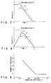
- FIG. 8 shows the velocity trajectory and the actual velocity of the optical head with time on the horizontal axis;
- FIG. 9 shows the number of mistracks with respect to the correction coefficient;
- FIG. 10 is a flowchart for explaining a seek operation in a first embodiment of the present invention; and
- FIG. 11 is a flowchart for explaining a seek operation in a second embodiment of the present invention.
- Hereinafter, a first embodiment of the present invention will be explained with reference to the accompanying drawings.
- FIG. 1 shows an
optical disk apparatus 100 associated with an information processing apparatus of the present invention and ahost apparatus 110 connected to this processing apparatus. Thehost apparatus 110 contains an optical disk controller 33, aCPU 111, amain memory 112, an I/O section 113, adisplay 114, and akeyboard 115. - At the surface of an
optical disk 1, recording tracks (grooves) are formed spirally or concentrically. Theoptical disk 1 is rotated at, e.g., a constant linear velocity by amotor 2, which is controlled by amotor control circuit 18. The recording and reproducing of information on and from theoptical disk 1 is effected by anoptical head 3 provided under theoptical disk 1. While in this embodiment, an optical disk allowing the recording of information by the formation of pits in the recording layer is used, an optical disk with a recording layer presenting a phase change or a multilayer recording film or a magneto-optical disk may be used. To use these optical disks, the construction including the optical head must be modified accordingly. - In the
optical head 3, anobject lens 6 is held by a wire or leaf spring (not shown). Theobject lens 6 is moved in the focusing direction (along the optical axis of the lens) by adriving coil 5 and in the tracking direction (in the direction perpendicular to the optical axis of the lens) by adriving coil 4. The laser light generated by asemiconductor laser oscillator 9 driven by alaser control circuit 14 passes through a collimator lens 11a, ahalf prism 11b, and theobject lens 6, and is focused as a small spot onto theoptical disk 1. The reflected light from theoptical disk 1 passes through theobject lens 6, thehalf prism 11b, a condenser lens 10a, and acylindrical lens 10b, and is directed to anoptical sensor element 8. Theoptical sensor element 8 is composed of four quadrantoptical sensor cells - FIG. 2 shows the arrangement of the
optical sensor element 8, ahead amplifier section 12, and anadder section 30 in more detail. Amplifiers 12a to 12d constitute thehead amplifier section 12, andadders adder section 30. - The output signal of the optical sensor cell 8a of the
optical sensor element 8 is supplied via the amplifier 12a to one input of each of theadders 30a and 30c. The output signal of the optical sensor cell 8c is supplied via theamplifier 12b to one input of each of theadders optical sensor cell 8b is supplied via theamplifier 12d to the other input of each of theadders optical sensor cell 8d is supplied via the amplifier 12c to the other input of each of theadders 30b and 30c. The output signals of theoptical sensor cells optical sensor element 8 are supplied via theamplifiers speed adder 41. - The output signal of the
adder 30a is supplied to the inverting input terminal of a differential amplifier OP1 constituting a trackerror signal circuit 42. The output signal of theadder 30b is supplied to the noninverting input terminal of the differential amplifier OP1. With these signals applied, the differential amplifier OP1 supplies a track error signal (or a track difference signal) indicating the difference between the outputs ofadders tracking control circuit 16 and atrack counter circuit 35 in FIG. 1. - The output signals of the
adders sum signal circuit 43 made up of an adder. The tracksum signal circuit 43 supplies a track sum signal indicating the sum of the output signals of theadders control circuit 15, thetracking control circuit 16, and thetrack counter circuit 35. The track sum signal supplied from the tracksum signal circuit 43 reflects the differences in the reflectivity on the surface of theoptical disk 1 and the diffraction when light crosses the track grooves. - In FIG. 1, the
tracking control circuit 16 generates a tracking signal according to the track error signal supplied from the differential amplifier OP1 and the track sum signal supplied from the tracksum signal circuit 43. The tracking signal is supplied to thedriving coil 4 of the tracking direction. The track error signal used in thetracking control circuit 16 is also supplied to a linear motor control circuit 17. - The
track counter circuit 35, using the track error signal from the trackerror signal circuit 42 and the track sum signal from the tracksum signal circuit 43, senses not only the light spot position (track number) on theoptical disk 1, but also the velocity of the light spot along the radius of the optical disk. The track number and the velocity sensed at thetrack counter circuit 35 are supplied to aCPU 23 and the linear motor control circuit 17, respectively. The pulses supplied from apulse correction circuit 53, explained later, in thetrack counter circuit 35 are transferred as track passing pulses to theCPU 23. The linear motor control circuit 17 controls the current flowing through a drivingcoil 13 of alinear motor 31 explained later on the basis of the track error signal from thetracking control circuit 16, the reference velocity supplied via a D/A converter 22 from theCPU 23, and the current velocity supplied from thetrack counter circuit 35. - The output signal of the adder 30c of FIG. 2 is supplied to the inverting input terminal of a differential amplifier OP2. The output signal of the
adder 30d is supplied to the noninverting input terminal of the differential amplifier OP2. With these signals supplied, the differential amplifier OP2 supplies a signal indicating the difference between the outputs of theadders 30c and 30d to the focusingcontrol circuit 15. The output signal of the focusingcontrol circuit 15 is supplied to the focusing drivingcoil 5, which is controlled so that the laser light may be always properly focused on theoptical disk 1. - After the focusing and the tracking have been effected as described above, the sum signal of the outputs of the individual optical sensor cells 8a to 8d of the
optical sensor element 8, i.e., the output of the high-speed adder 41 reflects the changes of the reflected light from pits and grooves formed on the tracks. This signal is supplied to asignal processing circuit 19, which reproduces the recorded information and address information (track number, sector number, etc.). The reproduced signal from thesignal processing circuit 19 is supplied via aninterface 32 to an optical disk controller 33 of the host apparatus. In the preceding stage to thelaser control circuit 14, a recordingsignal generator circuit 34 for modulating the recording signal is provided. - In the optical disk apparatus, there is provided a D/
A converter 22 for exchanging information between the focusingcontrol circuit 15, trackingcontrol circuit 16, linear motor control circuit 17, andCPU 23. Thelaser control circuit 14, focusingcontrol circuit 15, trackingcontrol circuit 16, linear motor control circuit 17,motor control circuit 18,signal processing circuit 19, recordingsignal generator circuit 34, and trackcounter circuit 35 are controlled by theCPU 23 via abus line 20. TheCUP 23 carries out a specific operation according to the program stored in amemory 24. - FIG. 3 is a block diagram of the
track counter circuit 35 of FIG. 1. As shown in the figure, thetrack counter circuit 35 comprises an AGC (automatic gain control)circuit 51, a track sense pulsesignal extractor circuit 52, apulse correction circuit 53, a period/velocity converter circuit 54, a track sumwaveform shaping circuit 56, a groovesense pulse circuit 57, adirection sensing circuit 58, and acounter 59. - The
AGC circuit 51, using a track sum signal, keeps the amplitude of the track error signal supplied from the trackerror signal circuit 42 at a constant level and eliminates noise signals caused by dust, dirt, flaws, etc. The output signal from theAGC circuit 51 is supplied to the track sense pulsesignal extractor circuit 52. - The track sense pulse
signal extractor circuit 52, using the gain-controlled track error, supplies a pulse per groove in the track. Thepulse correction circuit 53 removes noises from the track sense pulse signal, and supplies the noise-free signal to the period/velocity converter circuit 54, counter 59, andCPU 23. - The period/
velocity converter circuit 54 generates the velocity of theoptical head 3 by dividing the period of the pulse supplied from thepulse correction circuit 53 by time t (τ/t). The velocity signal thus obtained is supplied to the linear motor control circuit 17. The track sumwaveform shaping circuit 56 shapes the waveform of the track sum signal from the tracksum signal circuit 43, and supplies the waveform-shaped track sum signal to the groovesense pulse circuit 57. - The groove
sense pulse circuit 57 senses a groove from the track sum signal supplied from the track sumwaveform shaping circuit 56 and supplies a groove sense pulse. The groove sense pulse from the groovesense pulse circuit 57 is supplied to thedirection sensing circuit 58. Thedirection sensing circuit 58, using the phase difference between the track sense pulse and the groove sense pulse, judges the moving direction of the light spot on theoptical disk 1. - The counting direction (counting up or down) of the
counter 59 is switched by the direction signal from thedirection sensing circuit 58. Being switched in this way, thecounter 59 counts up or down according to the track sense pulses from thepulse correction circuit 53. Before a track seek operation, the number of tracks to be crossed is set for thecounter 59. As a result, the contents of thecounter 59 always indicate the number of the track on which the light spot is located on the optical disk (refer to Jpn. Pat. Appln. KOKAI Publication No. 5-36095). - The
memory 24 is provided with a velocity trajectory table 24a in which the velocity trajectory corresponding to the moving distance, i.e., the number of the remaining tracks to the target position is recorded, a number-of-remaining-tracks count section 24b in which the number of the remaining tracks from the current track to the track of the target position is recorded, a reference velocity computing table 24c in which value C for obtaining a reference velocity lower than the velocity trajectory by the specified value C during the deceleration is stored, and a reference velocity table 24d in which a previously computed reference velocity is stored. - The velocity trajectory contains a maximum-speed region of the
optical head 3 and a deceleration region for decelerating to an enough velocity to perform a tracking operation near the track of the target position. The time-speed characteristic shown in FIG. 4 can be graphed with the number of tracks on the horizontal axis as shown in FIG. 5. In the figures, the dotted lines represent examples of the accelerating courses when theoptical head 3 is driven using the velocity trajectory. In the velocity trajectory table 24a, the velocity trajectories corresponding to the number of the remaining tracks as shown in FIGS. 5 and 6 are stored. - FIG. 7 shows reference velocity A of the present invention used in actual control with respect to velocity trajectory B. The
CPU 23 reads value C from the reference velocity computing table 24c and obtains reference velocity A lower than the velocity trajectory B by the specified value C. - When being supplied with the destination target track number of the
optical head 3 from an optical disk controller 33 of thehost apparatus 110, theCPU 23 computes the number of tracks to be crossed, which is the difference between the number of the track of the target position and the current track number indicated by thecounter 59 of thetrack counter circuit 35. The number of tracks to be crossed is stored as the initial value of the number of the remaining tracks in the number-of-remaining-tracks count section 24b. TheCPU 23 counts down the contents of the number-of-remaining-tracks count section 24b each time a track passing pulse is supplied from thetrack counter circuit 35. TheCPU 23 also reads the velocity trajectory corresponding to the number of the remaining tracks in the number-of-remaining-tracks count section 24b from the velocity trajectory table 24a, and calculates a reference velocity lower than the velocity trajectory by the specified value C, using the reference velocity computing table 24c. TheCPU 23 supplies the computed reference velocity to the linear motor control circuit 17 via the D/A converter 22. - Now, the specified value C will be described.
- The velocity during deceleration can be considered to be a response of the velocity control system to a ramp input, provided the deceleration is constant. If the transfer function of the velocity control system is G(s), a steady-state deviation of E for a unit ramp input can be expressed as:

When the velocity control system of FIG. 1 is assumed to be of the I type, the transfer function can be expressed as:

where fc is the control band of the velocity control system. - Therefore, if a decelerating velocity is d, the steady-state velocity deviation Ed is given by

Namely, it can be seen that when deceleration is effected at a deceleration of d, the velocity of theoptical head 3 is greater by Ed than the velocity trajectory stored in the velocity trajectory table 24a. - Therefore, in this embodiment, the value k × Ed obtained by multiplying the steady-state deviation Ed by correction efficient k is defined as the specified value C and velocity control is performed using a value less than the velocity trajectory by k × Ed as a reference velocity during deceleration. This enables the actual velocity of the optical head to be controlled to a value close to the velocity trajectory.

FIG. 8 shows the actual velocity D when theoptical head 3 is controlled using reference velocity A less than the designed velocity trajectory B by the specified value C. The actual velocity D overlaps with the designed target velocity B. At the time E when a tracking operation is effected, the actual velocity of theoptical head 3 is already sufficiently low. Since the actual velocity deviation approaches the steady-state deviation Ed gradually as when the deceleration just started, it is desirable that in a short seek operation, the specified value C should be smaller than the steady-state deviation Ed. - During a seek operation, the time required for the light spot to move from a track to the next track varies significantly. Because the current velocity is obtained by dividing the track sense pulse period by the time, the change of the velocity leads to the change of the sensing time of the velocity. Therefore, the response frequency of the velocity control system also changes accordingly. The aforementioned correction coefficient k is for compensating for this. FIG. 9 shows the number of mistracks for correction coefficient k. The number of mistracks is the average value of the difference between the track number of the track reached by the light spot and the target track number at each seeking when random seeking is effected 1024 times. It can be seen from FIG. 9 that when correction coefficient k is smaller than 0.75, the number of mistracks increases rapidly. Therefore, it is desirable for practical use that correction coefficient k should be in the range from 1 to 0.75.
- The specified value C for computing a reference velocity does not necessarily have to be a constant value as described above, it may be varied as a function of the velocity, the moving distance, the destination position, and the type of disk.
- With this configuration, a seek operation of the
optical head 3 will be described, referring to the flowchart of FIG. 10. Here, it is assumed that theoptical head 3 is driven at a velocity shown in FIG. 7. - First, the optical disk controller 33 of the
host apparatus 110 supplies the destination target track number of theoptical head 3 to theCPU 23 via theinterface 32 and thebus 20. TheCPU 23 receives the track number indicating the current position of the optical head from thecounter 59 of thetrack counter circuit 35. TheCPU 23 calculates the difference between the target track number and the current track number. This difference is stored as the initial value of the number of the remaining tracks in the number-of-remaining-tracks memory 24b. TheCPU 23 judges the moving direction of theoptical head 3 on the basis of the target track number and the current track number, and supplies this direction to the linear motor control circuit 17 and thetrack counter circuit 35. - The
CPU 23 reads the velocity trajectory corresponding to the number of the remaining tracks from the velocity trajectory table 24a, computes a reference velocity lower than the velocity trajectory by the specified value C, using the reference velocity computing table 24c, and supplies the computed reference velocity to the linear motor control circuit 17 via the D/A converter 22. However, when the number of the remaining tracks is great and the optical head is outside the deceleration region to which the reference velocity is applied, the maximum velocity is supplied to the linear motor control circuit 17. - The linear motor control circuit 17 computes the difference between the velocity trajectory from the D/
A converter 22 and the current velocity Vc, and drives thelinear motor 31 at a current corresponding to the difference. TheCPU 23 decrements the number-of-remaining-tracks table 24b each time the light spot crosses a track. - When the number of the remaining tracks becomes 1 or less, the
CPU 23 causes the focusingcontrol circuit 15 and thetracking control circuit 16 to operate for a focusing and a tracking operation. Information is recorded or reproduced onto or from the track accessed in this way. - A second embodiment of the present invention will be explained. While in the first embodiment, a reference velocity is computed during a seek operation, using the contents C of the reference velocity computing table 24c, a reference velocity can be computed in advance and stored in a table 24d, and a seek operation can be controlled by directly referring to the stored reference velocity. In the table 24d, reference velocity VR (including the maximum velocity and portion A) indicated by a longer dash line is stored. A flowchart for explaining the operation of the second embodiment is shown in FIG. 11.
- As described above, after having received the destination target track number of the
optical head 3 from the optical disk controller 33, theCPU 23 stores the difference between the current track number and the target track number as the initial value of the number of the remaining tracks T in the number-of-remaining-tracks memory 24b. - The
CPU 23 supplies the moving direction of theoptical head 3 to the linear motor control circuit 17 and thetrack counter circuit 35. TheCPU 23 reads a reference velocity VR corresponding to the number of the remaining tracks T from the table 24d, and supplied the reference velocity VR to the D/A converter 22. The D/A converter 22 supplies an analog voltage corresponding to the reference velocity VR to the linear motor control circuit 17. The linear motor control circuit 17 compares the voltages representing the current velocity Vc and the reference velocity VR, and supplies a current corresponding to VR - Vc. As a result, theoptical head 3 is accelerated. - Each time the light spot crosses a track on the
optical disk 1, thetrack counter circuit 35 transfers a track passing pulse to theCPU 23, which then decrements the number-of-remaining-tracks table 24b accordingly. TheCPU 23 judges whether the current number of the remaining tracks T is 1 or less. If not T ≦ 1 (i.e., NO), theCPU 23 reads the reference velocity VR corresponding to the number of the remaining tracks T and supplies VR to the D/A converter 22. - After the current velocity Vc has reached the reference velocity VR, VR - Vc is negative and consequently the
linear motor 31 is driven in the opposite direction to that during acceleration. This decelerates the optical head. When the number of the remaining tracks becomes 1 or less, a focusing and a tracking operation are performed.
Claims (6)
- An information processing apparatus (100) accessing a target track on an information recording medium (1) on which tracks are formed with information recorded along said tracks, characterized by comprising:
means (3) for acquiring said information recorded along said tracks and providing said information;
first sensing means (35, 23) for sensing a distance from the current position of said acquiring means to said target track;
means (24d) for storing a reference velocity data of said acquiring means (3) corresponding to the distance sensed by said first sensing means (35, 23), said reference velocity data containing deceleration data for said acquiring means (3) to be decelerated as approaching said target track, and said deceleration data being a velocity obtained by subtracting a predetermined value which is less than a steady-state velocity deviation from a velocity trajectory of said acquiring means (3);
means (31) for moving said acquiring means (3) toward said target track so as to cross said tracks, according to said reference velocity data stored in said storing means (24d);
second sensing means (35, 23) for sensing the current velocity of said acquiring means moved by said moving means; and
means (23, 24) for comparing said current velocity sensed at said second sensing means (35, 23) with the velocity indicated by said reference velocity data supplied to said moving means (31) and, when there is a difference between the two, controlling said moving means (31) so that said current velocity may coincide with the velocity indicated by said velocity data, thereby causing said acquiring means to be decelerated at a velocity equal to said velocity trajectory. - An information processing apparatus according to claim 1, characterized in that said storing means (24d) includes:
first storage means (24a) for storing the velocity trajectory data of said acquiring means (3) corresponding to the distance sensed by said first sensing means (35, 23);
computing means (23, 24) for subtracting a predetermined value which is less than said steady-state velocity deviation from said velocity trajectory data stored in said first storage means (24a) and generating said deceleration data; and
second storage means (24d) for storing said deceleration data generated at said computing means (23, 24). - An information processing apparatus according to claim 2, characterized in that said first storage means (23) further includes means (23, 24) for obtaining said steady-state deviation from a response characteristic of a velocity control system of said acquiring means (3) containing said moving means (31), said first and second sensing means (35, 23), and said comparing means (23, 24).
- An information processing apparatus according to claim 1, characterized by further comprising crossing sensing means (19, 23) for, when said acquiring means (3) is moved by said moving means (31), sensing that said acquiring means (3) has crossed said track, by processing said information from said acquiring means (3), and providing a signal representing the crossing sensed, wherein said first sensing means (35, 23) contains means for judging the current position of said acquiring means (3) on the basis of the signal from said crossing sensing means (19, 23), and said second sensing means (35, 23) contains means for judging the current velocity of said acquiring means (3) on the basis of the period of a signal from said crossing sensing means (19, 23).
- An information processing according to claim 1, characterized in that said information processing apparatus (100) is an optical-disk apparatus and said recording medium (1) is an optical disk, wherein said acquiring means (3) includes means (9, 14) for projecting a light beam onto said optical disk and means (19) for receiving said light beam reflected from said optical disk to provide said information.
- An information processing apparatus according to claim 5, characterized in that: said acquiring means is an optical head; said first sensing means (35, 23) includes means for sensing the number of tracks between the current position of said optical head and said target track; said storing means (24d) contains means for storing the reference velocity data of said optical head corresponding to said number of tracks sensed by said first sensing means (35, 23); and said moving means (31) includes means (23, 24) for reading said reference velocity data corresponding to the number of tracks sensed by said first sensing means from said storing means each time said number of tracks changes as a result of the movement of said optical head, and means (17) for driving said optical head toward said target track so as to cross said tracks, according to said reference velocity data read by said reading means (23, 24).
Applications Claiming Priority (2)
| Application Number | Priority Date | Filing Date | Title |
|---|---|---|---|
| JP5065255A JPH06274901A (en) | 1993-03-24 | 1993-03-24 | Information processing device |
| JP65255/93 | 1993-03-24 |
Publications (2)
| Publication Number | Publication Date |
|---|---|
| EP0617416A1 true EP0617416A1 (en) | 1994-09-28 |
| EP0617416B1 EP0617416B1 (en) | 1999-04-14 |
Family
ID=13281626
Family Applications (1)
| Application Number | Title | Priority Date | Filing Date |
|---|---|---|---|
| EP94102653A Expired - Lifetime EP0617416B1 (en) | 1993-03-24 | 1994-02-22 | Information processing apparatus |
Country Status (4)
| Country | Link |
|---|---|
| US (1) | US5497360A (en) |
| EP (1) | EP0617416B1 (en) |
| JP (1) | JPH06274901A (en) |
| DE (1) | DE69417793T2 (en) |
Cited By (1)
| Publication number | Priority date | Publication date | Assignee | Title |
|---|---|---|---|---|
| EP0969453A1 (en) * | 1998-07-03 | 2000-01-05 | Deutsche Thomson-Brandt GmbH | Fast and precise positioning of a reading and/or writing head in a data player and/or recorder |
Families Citing this family (10)
| Publication number | Priority date | Publication date | Assignee | Title |
|---|---|---|---|---|
| US5677899A (en) | 1991-02-15 | 1997-10-14 | Discovision Associates | Method for moving carriage assembly from initial position to target position relative to storage medium |
| KR0129245B1 (en) * | 1994-07-14 | 1998-04-18 | 구자홍 | Spindle Motor Control Circuit of CD-ROM Drive and Its Method |
| US6181651B1 (en) | 1996-03-26 | 2001-01-30 | Matsushita Electric Industrial Co., Ltd. | Optical recording/reproducing apparatus |
| KR19980021850A (en) * | 1996-09-19 | 1998-06-25 | 구자홍 | Fast Access Method of Optical Disc Player |
| US5802019A (en) * | 1997-07-24 | 1998-09-01 | Nec Corporation | Access control system for optical disk device |
| TWI233099B (en) * | 2001-08-30 | 2005-05-21 | Via Tech Inc | Method for deciding the direction of pick-up head of disk driver while crossing tracks |
| TWI233111B (en) * | 2003-05-09 | 2005-05-21 | Ind Tech Res Inst | Track jump apparatus for accessing an optical storage medium and position detection method thereof |
| US20080117734A1 (en) * | 2006-11-22 | 2008-05-22 | Hon Hai Precision Industry Co., Ltd. | Track-jumping method for optical disk drive |
| TW201349235A (en) * | 2012-05-23 | 2013-12-01 | Hon Hai Prec Ind Co Ltd | Optical disk reading and writing device, tracking servo and tracking method thereof |
| JP2018113085A (en) * | 2017-01-10 | 2018-07-19 | 株式会社東芝 | Magnetic disk device and write method |
Citations (5)
| Publication number | Priority date | Publication date | Assignee | Title |
|---|---|---|---|---|
| US4591933A (en) * | 1983-11-28 | 1986-05-27 | Computer Memories, Incorporated | Disk drive head positioner with optimized seek operation |
| US4622604A (en) * | 1983-05-23 | 1986-11-11 | Kabushiki Kaisha Toshiba | Magnetic head controlling apparatus |
| JPS6476574A (en) * | 1987-09-18 | 1989-03-22 | Pioneer Electronic Corp | High-speed searching method in disk player |
| EP0408392A2 (en) * | 1989-07-14 | 1991-01-16 | Sharp Kabushiki Kaisha | Optical disk recording and reproducing apparatus |
| EP0464992A1 (en) * | 1990-06-29 | 1992-01-08 | Quantum Corporation | Adaptive track seeking for disc drives |
Family Cites Families (2)
| Publication number | Priority date | Publication date | Assignee | Title |
|---|---|---|---|---|
| JP2573301B2 (en) * | 1988-04-22 | 1997-01-22 | 株式会社東芝 | Disk unit |
| JPH0536095A (en) * | 1991-07-29 | 1993-02-12 | Toshiba Corp | Count circuit for disk device |
-
1993
- 1993-03-24 JP JP5065255A patent/JPH06274901A/en active Pending
-
1994
- 1994-02-22 EP EP94102653A patent/EP0617416B1/en not_active Expired - Lifetime
- 1994-02-22 DE DE69417793T patent/DE69417793T2/en not_active Expired - Fee Related
- 1994-02-25 US US08/202,134 patent/US5497360A/en not_active Expired - Lifetime
Patent Citations (5)
| Publication number | Priority date | Publication date | Assignee | Title |
|---|---|---|---|---|
| US4622604A (en) * | 1983-05-23 | 1986-11-11 | Kabushiki Kaisha Toshiba | Magnetic head controlling apparatus |
| US4591933A (en) * | 1983-11-28 | 1986-05-27 | Computer Memories, Incorporated | Disk drive head positioner with optimized seek operation |
| JPS6476574A (en) * | 1987-09-18 | 1989-03-22 | Pioneer Electronic Corp | High-speed searching method in disk player |
| EP0408392A2 (en) * | 1989-07-14 | 1991-01-16 | Sharp Kabushiki Kaisha | Optical disk recording and reproducing apparatus |
| EP0464992A1 (en) * | 1990-06-29 | 1992-01-08 | Quantum Corporation | Adaptive track seeking for disc drives |
Non-Patent Citations (1)
| Title |
|---|
| PATENT ABSTRACTS OF JAPAN vol. 13, no. 303 (P - 896) 12 July 1989 (1989-07-12) * |
Cited By (3)
| Publication number | Priority date | Publication date | Assignee | Title |
|---|---|---|---|---|
| EP0969453A1 (en) * | 1998-07-03 | 2000-01-05 | Deutsche Thomson-Brandt GmbH | Fast and precise positioning of a reading and/or writing head in a data player and/or recorder |
| WO2000002198A1 (en) * | 1998-07-03 | 2000-01-13 | Deutsche Thomson Brandt Gmbh | Fast and precise positioning of a reading and/or writing head in a data player and/or recorder |
| US6873577B1 (en) | 1998-07-03 | 2005-03-29 | Thomson Licensing S.A. | Optical head position control for optical recording device |
Also Published As
| Publication number | Publication date |
|---|---|
| JPH06274901A (en) | 1994-09-30 |
| EP0617416B1 (en) | 1999-04-14 |
| DE69417793D1 (en) | 1999-05-20 |
| DE69417793T2 (en) | 1999-12-23 |
| US5497360A (en) | 1996-03-05 |
Similar Documents
| Publication | Publication Date | Title |
|---|---|---|
| US4918676A (en) | Track accessing apparatus for optical disk | |
| KR920005795B1 (en) | Optical disk apparatus | |
| US5497360A (en) | Optical disc apparatus with accessing using only reference velocity during acceleration and reference and moving velocities during deceleration | |
| US5077716A (en) | Optical recording and reproducing system having an accurate high-speed optical head positioning apparatus | |
| US5781516A (en) | Multiplane optical disc apparatus and access control method thereof | |
| EP0536737B1 (en) | Information recording/reproducing apparatus for optical information recording medium | |
| US4918680A (en) | Focus-servo correction utilizing storage of detected focus errors | |
| US5566148A (en) | Optical disk tracking system for searching a target track based on a table of compensation reference velocity | |
| US5317550A (en) | Apparatus and method for track access | |
| US5148420A (en) | Recording information apparatus having a head speed detector | |
| US5058092A (en) | Method for accessing a control track by positioning an optical head at the center of the control track | |
| EP0607045B1 (en) | Information recording and/or reproducing apparatus and information recording and/or reproducing method | |
| US5675560A (en) | Information recording/reproducing apparatus with function of seeking light beam to target position, and method therefor | |
| JPH05298717A (en) | Optical head access controller | |
| US5515349A (en) | Track seek method and device for use with an optical information recording and reproducing apparatus | |
| US6195311B1 (en) | Method of determining a distance to be moved by an optical pick-up | |
| US5231618A (en) | Optical disc system | |
| JPH09167357A (en) | Track jump controller for optical recording and reproducing device | |
| JP2732590B2 (en) | Recording medium processing device | |
| JP2720829B2 (en) | Optical head seek speed controller | |
| JP2001118259A (en) | Optical information recording and reproducing device | |
| JP2724002B2 (en) | Optical card device | |
| JP2778822B2 (en) | Access control device | |
| JP2732587B2 (en) | Disk device access method | |
| JPH06325554A (en) | Access controller and control method |
Legal Events
| Date | Code | Title | Description |
|---|---|---|---|
| PUAI | Public reference made under article 153(3) epc to a published international application that has entered the european phase |
Free format text: ORIGINAL CODE: 0009012 |
|
| 17P | Request for examination filed |
Effective date: 19940222 |
|
| AK | Designated contracting states |
Kind code of ref document: A1 Designated state(s): DE NL |
|
| 17Q | First examination report despatched |
Effective date: 19970603 |
|
| GRAG | Despatch of communication of intention to grant |
Free format text: ORIGINAL CODE: EPIDOS AGRA |
|
| GRAG | Despatch of communication of intention to grant |
Free format text: ORIGINAL CODE: EPIDOS AGRA |
|
| GRAH | Despatch of communication of intention to grant a patent |
Free format text: ORIGINAL CODE: EPIDOS IGRA |
|
| GRAH | Despatch of communication of intention to grant a patent |
Free format text: ORIGINAL CODE: EPIDOS IGRA |
|
| GRAA | (expected) grant |
Free format text: ORIGINAL CODE: 0009210 |
|
| AK | Designated contracting states |
Kind code of ref document: B1 Designated state(s): DE NL |
|
| REF | Corresponds to: |
Ref document number: 69417793 Country of ref document: DE Date of ref document: 19990520 |
|
| PLBE | No opposition filed within time limit |
Free format text: ORIGINAL CODE: 0009261 |
|
| STAA | Information on the status of an ep patent application or granted ep patent |
Free format text: STATUS: NO OPPOSITION FILED WITHIN TIME LIMIT |
|
| 26N | No opposition filed | ||
| PGFP | Annual fee paid to national office [announced via postgrant information from national office to epo] |
Ref country code: NL Payment date: 20080203 Year of fee payment: 15 Ref country code: DE Payment date: 20080214 Year of fee payment: 15 |
|
| NLV4 | Nl: lapsed or anulled due to non-payment of the annual fee |
Effective date: 20090901 |
|
| PG25 | Lapsed in a contracting state [announced via postgrant information from national office to epo] |
Ref country code: NL Free format text: LAPSE BECAUSE OF NON-PAYMENT OF DUE FEES Effective date: 20090901 |
|
| PG25 | Lapsed in a contracting state [announced via postgrant information from national office to epo] |
Ref country code: DE Free format text: LAPSE BECAUSE OF NON-PAYMENT OF DUE FEES Effective date: 20090901 |